ANSYS Project: Verification of Weld Joints
Aim:
To perform a static structural analysis for the verification of welded joints and analyse different cases with different materials.
- Stainless Steel as the material o for both weldments and plates.
- Aluminium Alloy:as the material for weldments and Plate material as stainless steel.
- Bronze as weldment material In order to simulate Brazing, Stainless Steel to both plates and Copper to the Ribs.
Theory:
By utilizing intense heat to melt the components together and then allowing them to cool, which results in fusion, welding is a manufacturing method that unites materials, often metals or thermoplastics. Welding is separate from lower temperature metal-joining methods that don't melt the base metal, such brazing and soldering. According to the weld configuration (butt, complete penetration, fillet, etc.), the joint can be stronger than the base metal after melting the base metal and adding a filler material to create a pool of molten material (the weld pool) (parent metal). To create a weld, pressure can either be applied alone, in combination with heat, or both. In order to prevent contamination or oxidation of the filler metals or molten metals during welding, a shield is also necessary.
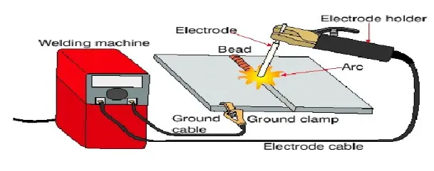
Figure: Components of an Arc Welding [reference]
Welding may be done using a variety of energy sources, such as gas flames (chemical), electric arcs (electrical), lasers, electron beams, friction, and ultrasound. Welding may be done in a variety of settings, including the open air, under water, and in space, despite the fact that it is frequently an industrial activity. Welding is a risky activity, thus safety measures must be taken to prevent burns, electric shocks, visual impairment, inhalation of toxic fumes, and exposure to strong UV radiation.
Blacksmiths had been joining iron and steel by heating and hammering for millennia, and until the end of the 19th century, there was only one kind of welding available: forge welding. The earliest welding techniques to emerge were arc and oxy-fuel welding, which were followed quickly by electric resistance welding. The early 20th century saw rapid advancements in welding technology as the need for durable and affordable joining techniques increased due to the global wars. Following the wars, a number of contemporary welding techniques were created, including semi-automatic and automatic procedures like gas metal arc welding, submerged arc welding, flux cord arc welding, and electro slag welding, as well as manual techniques like shielded metal arc welding, which is currently one of the most popular welding techniques. With advancements proceeded the creation of Laser Beam welding, Electron Beam welding, Magnetron sputtering and Stir friction welding. Towards the end of the century. Robot welding is becoming ubiquitous in industrial settings as science develops, and researchers are always coming up with novel welding techniques and learning more about weld quality.
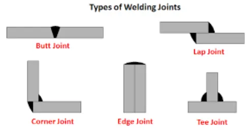
A brazed joint is made in a completely different manner from a welded joint. The first big difference is in temperature – brazing does not melt the base metals. Brazing temperatures are also significantly lower than welding temperatures for the same base metals, using less energy.
Objectives:
- Getting ready with the Weld Joint assemble model developed in Solidworks and importing it into the Ansys Workbench for static structural Analysis.
- Apply Boundary Conditions by setting up the contacts and applying the fixed and load boundary conditions.
- Determine Directional Deformation, Weld Stress and Elastic Strain results for the performed simulation.
- Repeating the simulation for other cases of different material.
- Evaluation and comparison of the results.
Analysis Setup:
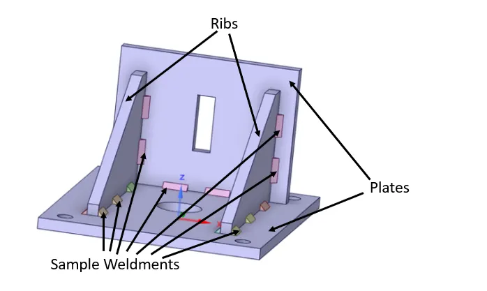
A static structural analysis is to be conducted for the welded joints of ribs and plats for three different cases of specific materials. The material of Plate is set to be structutal steel for all three cases.
- Geometry
The 3D assembly model of the Weld Joints is developed in SOLIDWORKS is shown in figure below: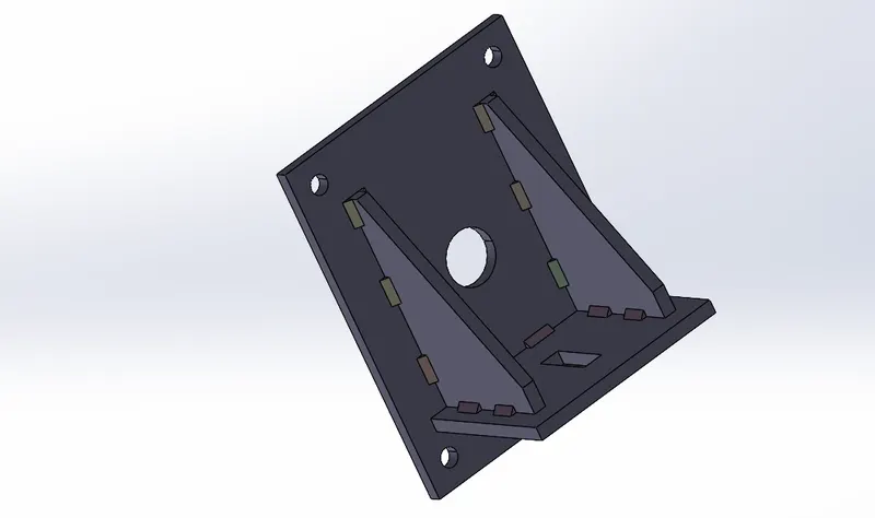
These models are then imported to Ansys Mechanical Static Structural Workbench for the analysis. - Material Properties
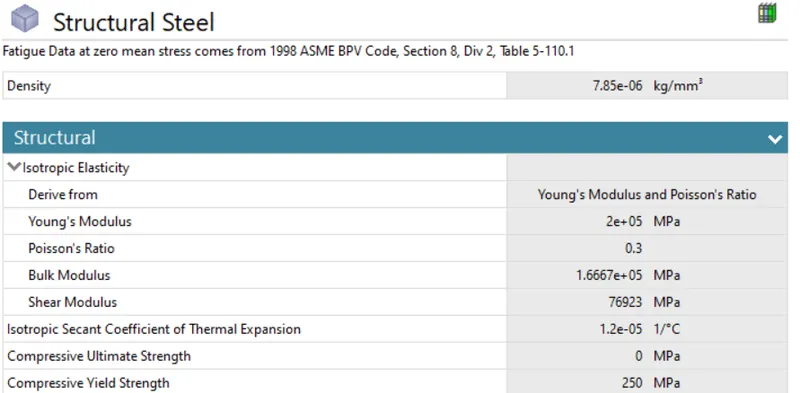
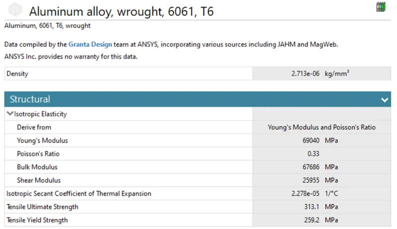
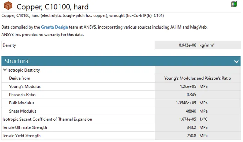
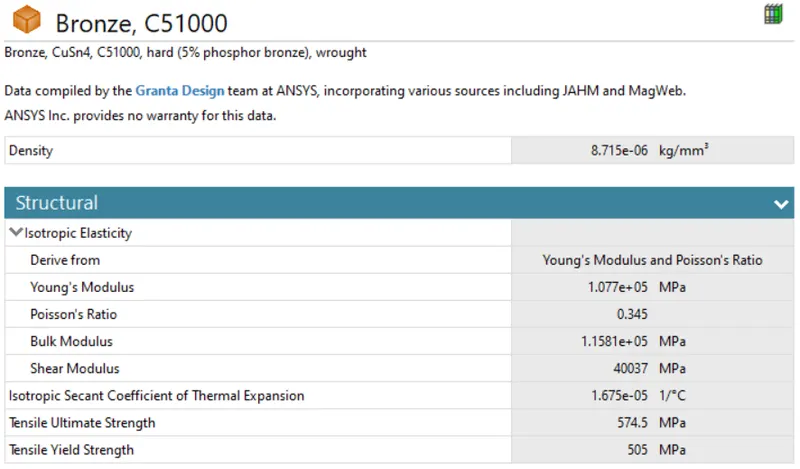
The material of Plates is set to be structural steel for all the 3 analysis cases. The material of Ribs are Structural Steel for the first 2 cases, but for the third case, the material is assigned as Copper. The material of weldments is different for each each. For the first case, the material structural steel is assigned, Aluminum Alloy for the second and Bronze for the third case. The material properties are given below:
- Structural Steel
- Aluminum Alloy
- Copper
- Bronze
- Structural Steel
- Contact Details
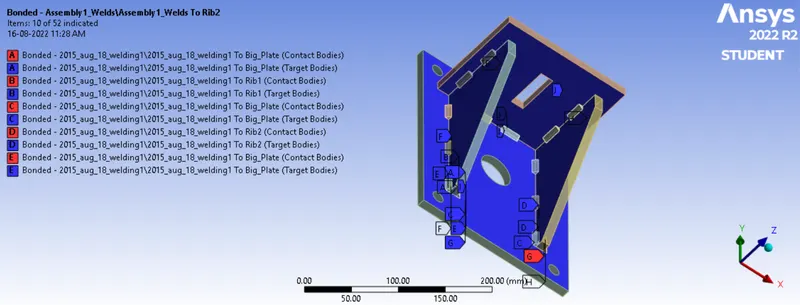
With a frictional value of 0.2, the direct contact between the ribs and plates is a frictional contact. Since all of the plates are flat, it is possible to choose the contact and the target for each contact at arbitrary while taking into account the benefits of utilizing Augmented Lagrange to prevent interpenetrations. This formulation is utilized for all frictional interactions. All the contact of weldments with the ribs and plats are set as bonded.
- Contact of Weldments with Ribs and Plats:
- With Ribs and Plats:
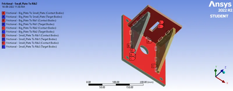
- Contact of Weldments with Ribs and Plats:
- Meshing
The appropriate element size was finalized by iteration default element size and a body mesh is used with 7mm refinement on the plates of the geometry was finalized. The total number of nodes and elements generated are 25808 and 4126 respectively. The generated mesh can be seen below: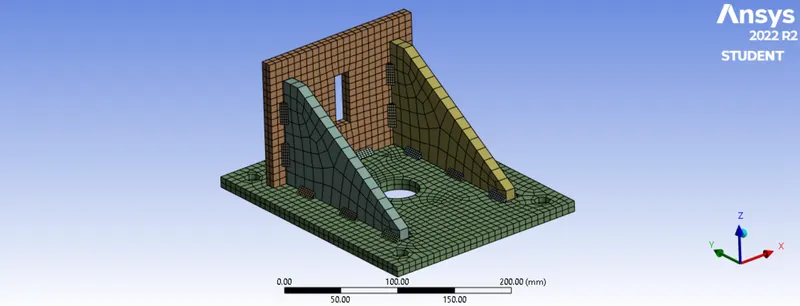

A mesh metric was used to identify elements based on their quality, and it can be observed that the elements of the lowest quality are minimum. The majority of the elements have very high quality values ranging from 0.42423 to 0.9904 with an average value of 0.85389. As a result, the mesh is of good quality. - Boundary Condition
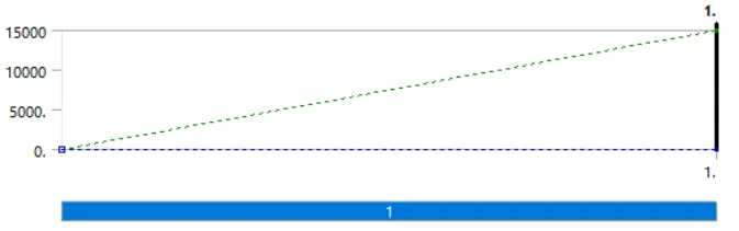
The analysis is set up for 1 step. This does not control the time step but is only an indication of points where boundary changes. the time step is auto controlled by specifying the initial, Minimum and Maximum time step.
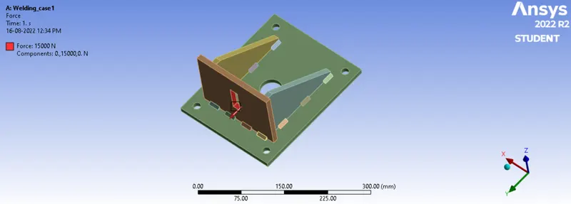
- The fixed support is set up at the 5 holes of the base plate.
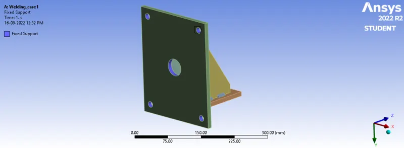
- A 15000N force is applied to the rectangular hole of the sub-plate in the Y-direction.
- The fixed support is set up at the 5 holes of the base plate.
Results:
- Case 1: Stainless steel material for both weldments and plates. No need to add flux to the weldments.
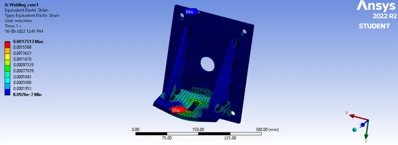
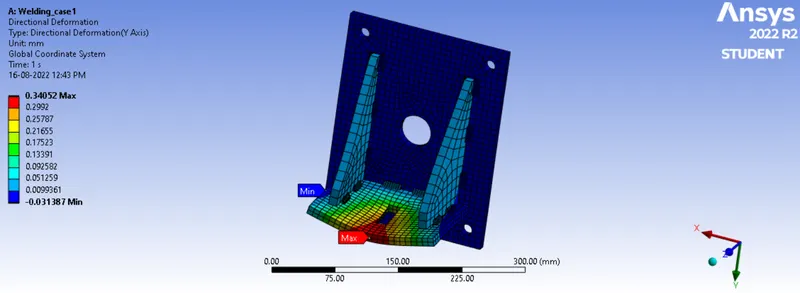
The observation obtained for the case 1 is shown below:
- Equivalent Elastic Strain:
- Directional Deforamation:
- Weld Stress:
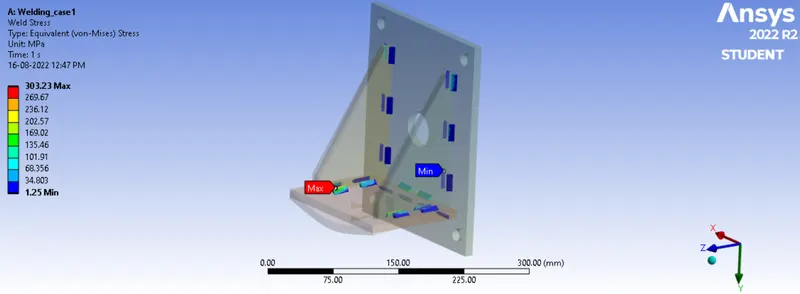
The weld joint that experiences the highest equivalent stress is identified which can be seen in the result above. - Safety Factor:
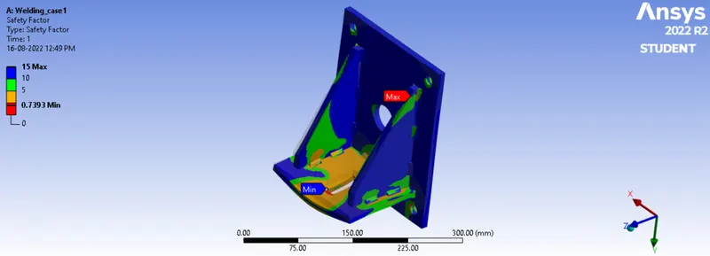
At certain location on the bottom plate, even a safety factor less that one is found, which is not a good design. Certain weld joints also seemed to have lower FOS, which is almost same to the weld joints where maximum stress is acting. So the weld in this region should be increased.
- Animation: Total Deformation
- Animation: Total Deformation
- Equivalent Elastic Strain:
- Case 2: Weld material is Aluminium Alloy and the Plate material to be used is stainless steel.
The observation obtained for the case 2 is shown below:
- Equivalent Elastic Strain:
- Directional Deformation:
- Weld Stress:
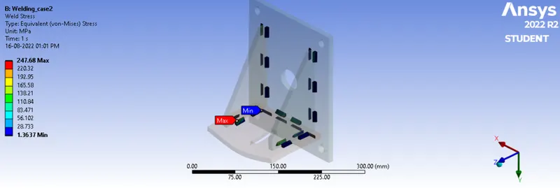
The weld joint that experiences the highest equivalent stress is identified which can be seen in the result above. - Safety Factor:
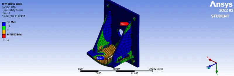
At certain location on the bottom plate, even a safety factor less that one is found, which is not a good design. Certain weld joints also seemed to have lower FOS, which is almost same to the weld joints where maximum stress is acting. So the weld in this region should be increased.
- Animation: Directional Deformation
- Animation: Directional Deformation
- Equivalent Elastic Strain:
- Case 3: Weld material is Bronze, the Plate material used is stainless steel, and the ribs are Copper.
The observation obtained for the case 3 is shown below:
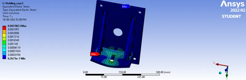
- Equivalent Elastic Strain:
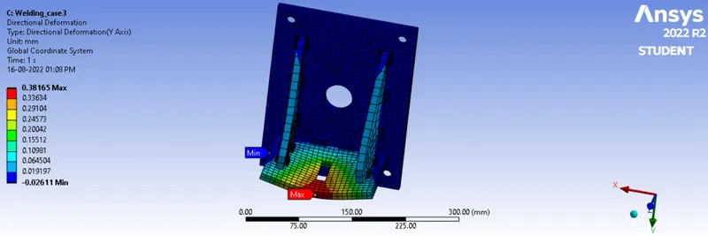
- Directional Deformation:
- Weld Stress:
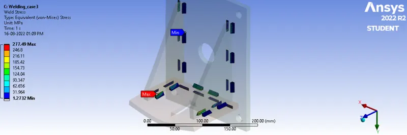
The weld joint that experiences the highest equivalent stress is identified which can be seen in the result above. - Safety Factor:
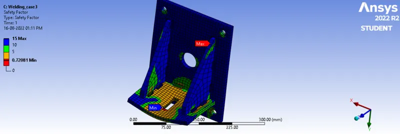
At certain location on the bottom plate, even a safety factor less that one is found, which is not a good design. Certain weld joints also seemed to have lower FOS, which is almost same to the weld joints where maximum stress is acting. So the weld in this region should be increased.
- Animation: Directional Deformation
- Animation: Directional Deformation
- Equivalent Elastic Strain:
- Comparison of Cases:
The table below summarize the observation values for each cases:
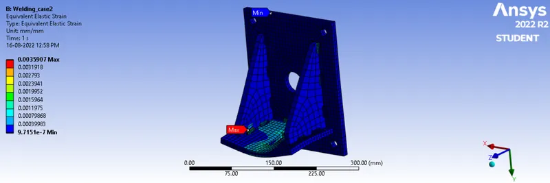
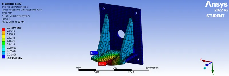
Case 1 Case 2 Case 3 Maximum Directional Deformation 0.34052 mm 0.35607 mm 0.38165 mm Maximum Elastic Strain 1.7513e-003 mm/mm 3.5907e-003 mm/mm 2.5823e-003 mm/mm Maximum Stress on Welds 303.23 MPa 247.68 MPa 277.49 MPa
From the table, the least amount of deformation occurs at the plate where force is applied since the steel weld has the maximum stress. While aluminum and bronze are unable to withstand high stresses, welding results in modest stress but extremely high strain, which causes the plate to bend significantly. The stainless steel weld is therefore the best choice out of the three.
Conclusion:
The verification of weld joints has been analyzed succesfully, where the weldments of different material has been compared and for the given application, the stainless steel weldments has been chosen because of its capabilty to withstand high stress.
The weld joint where the maximum stress occurs has been identified. It is the same joint for all the three cases. In order to releave it from the excess stress acting on it, further weldments by the side of it needed to be added.