Battery Technology Project: Configuration and Characteristics of Li-Ion Battery Model
Aim:
To configure the generic battery model in MATLAB from datasheet of a lithium ion battery and to simulate its charge discharge using UDDS data.
Theory:
A lithium-ion battery, also known as a Li-ion battery, is a type of rechargeable battery in which lithium ions move from the negative electrode to the positive electrode via an electrolyte during discharge and back again during charging. Li-ion batteries use an intercalated lithium compound as the positive electrode material and typically graphite as the negative electrode material. Li-ion batteries have a high energy density, no memory effect (with the exception of LFP cells), and a low self-discharge rate. Cells can be designed to prioritise either energy or power density.
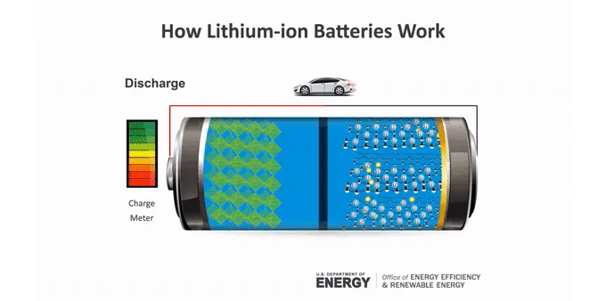
Figure: How Lithium-ion Batteries work [rebelbatteries, link]
During the discharge process, The anode is a negative electrode that generates electrons for the battery's external circuit. When two batteries are connected, an electron buildup occurs at the anode, resulting in a potential difference between the two electrodes. The electrons will naturally try to redistribute themselves; however, the electrolyte will prevent this, so when an electrical circuit is connected, it provides a clear path for the electrons to move from the anode to the cathode, thereby powering the circuit to which it is connected.
Lithium atoms split at the anode (-ve) of a lithium-ion battery. This results in electrons and lithium ions (lithium atoms with a positive charge). An electrolyte transports lithium ions within the battery to the cathode (+ve). Electrons cannot generally pass through this material. As a result, the electrons travel to the cathode via an external circuit. This generates an electric current capable of powering a device. The electrons combine with the lithium ions at the cathode for another chemical reaction. This process is reversed when charging a battery. The ions and electrons return to the anode. The anode in a lithium-ion battery is typically graphite. The lithium ions are tucked between the graphite's atom-thin layers. The cathode can be made from a variety of lithium-containing materials.
The Battery block in Simulink represents the most common types of rechargeable batteries using a generic dynamic model. Temperature and aging (due to cycling) effects can be specified for Lithium-Ion battery type. This block also has the possibilty to select the in built battery type. The figure below shows the equivalent circuit that the block models.
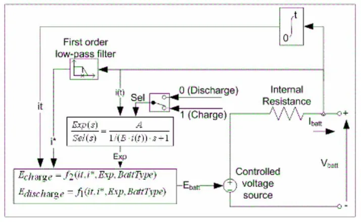
For the lithium-ion battery type, the model uses these equations.
Discharge Model (`i"*"` > 0)
`f_1(it,i"*",i)=E_0−K*Q/(Q−it)⋅i"*"−K⋅Q/(Q−it)⋅it+A⋅exp(−B⋅it)`
Charge Model (`i"*"`< 0)
`f_2(it,i"*",i)=E_0−K⋅Q/(it+0.1⋅Q)⋅i"*"−K⋅Q/(Q−it)⋅it+A⋅exp(−B⋅it)`
Where, `E_0` is the constant voltage in V, `K` is the polarization constant in V/Ah or polarization resistance in Ohms, `i"*"` is the low-frequency current dynamics in A, `i` is the battery current in A, `it` is the extracted capacity in Ah, `Q` is the maximum battery capacity in Ah, `A` is the exponential voltage in V, and `B` is the exponential capacity in Ah−1.
UDDS Drive Cycle:
The FTP-72 (Federal Test Procedure) cycle in the United States is also known as the Urban Dynamometer Driving Schedule (UDDS) or the LA-4 cycle (CFR 40, 86, App.I) [2656]. This cycle should not be confused with the heavy-duty vehicle UDDS schedule. The cycle simulates a 7.5-mile (12.07-kilometer) urban route with frequent stops. The top speed is 56.7 miles per hour (91.25 kilometres per hour), and the average speed is 19.6 miles per hour (31.5 kilometres per hour).
The cycle is divided into two parts: (1) 505 seconds (5.78 kilometres at 41.2 kilometres per hour average speed) and (2) 867 seconds. The first phase is characterised by a cold start. The weighting factors for the first and second phases are 0.43 and 0.57, respectively. Emissions are measured in grammes per mile or kilogrammes per kilometres. The same engine driving cycle is known as the ADR 27 (Australian Design Rules) cycle in Australia and as the A10 or CVS (Constant Volume Sampler) cycle in Sweden. In Sweden, the weighting factors for both phases are the same.
Objectives:
- To read a lithium ion cell datasheet.
- To understand the theory of Lithium-Ion Cell.
- To configure the generic battery model in MATLAB
- To Simulate generic battery model charge discharge using UDDS data.
Lithium-Ion Battery Data Sheet:
The data sheet of the battery model LIR18650 2600mAh was considered for this study on specifications of lithium ion cells. The data sheet for the same can be downloaded from the below link:
https://www.ineltro.ch/media/downloads/SAAItem/45/45958/36e3e7f3-2049-4adb-a2a7-79c654d92915.pdf
- The Basic characteristics of the Lithium-Ion Battery taken from the data sheet are as follows:
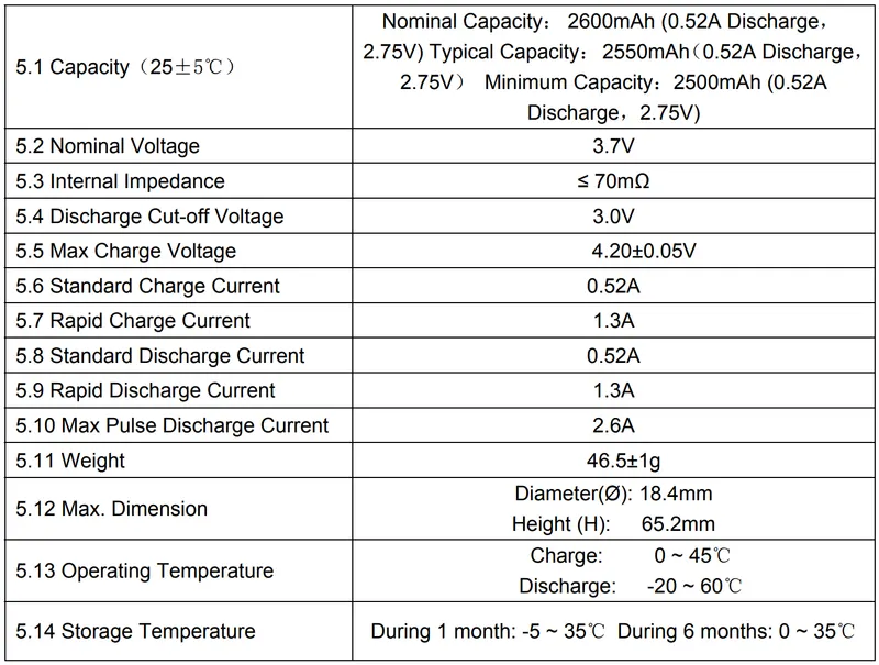
From this list the nominal capacity, nominal voltage, Internal Impedance, Discharge Cut-off Voltage, Max Charge Voltage, Standard Charge Current, Rapid Charge Current, and Standard Discharge Current data need to be fed into the Simulink model for the simulation.
SIMULINK Model of Lithium-Ion Battery Model:
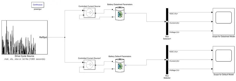
Explanation of the Model:
Two battery blocks are used in this model. For the first battery block, the parameter values in the datasheet are used, while for the second battery block, the battery block's default values are used. This open up the possibilty to compare the Battery characteristics for both the cases if need. The blocks used in the Simulink model are explained below:
- Drive Cycle Source: It is very simple to feed drive cycle data in any format into the Drive Cycle Source block for further simulation. To feed the data file, open the block and choose the type of file needed, as well as the file itself from its destination. The drive cycle data can be downloaded from the epa.gov website as provided below:
https://www.epa.gov/sites/production/files/2015-10/uddscol.txt
This obtained data is then saved in an excel sheet which is then imported to the Drive Cycle source block in the excel sheet format. - Controlled Current Source: The Simulink input signal is converted into an equivalent current source. The generated current is controlled by the block's input signal. One can start his or her circuit with a specific AC or DC voltage. To begin the simulation in a steady-state, connect the block input to a signal that begins as a sinusoidal or DC waveform corresponding to the initial values.
- Battery: The battery block from Simulink is used to configure a lithium-ion battery model, which can be found in the directory: Electrical/Specialized Power Systems/Electric Drives/Extra Sources. Several vector signal output ports provide SoC%, Current, and Voltage signals. To obtain each output separately, a bus selector block can be used. The following parameter values according to the datasheet was provided to the block as shown below:
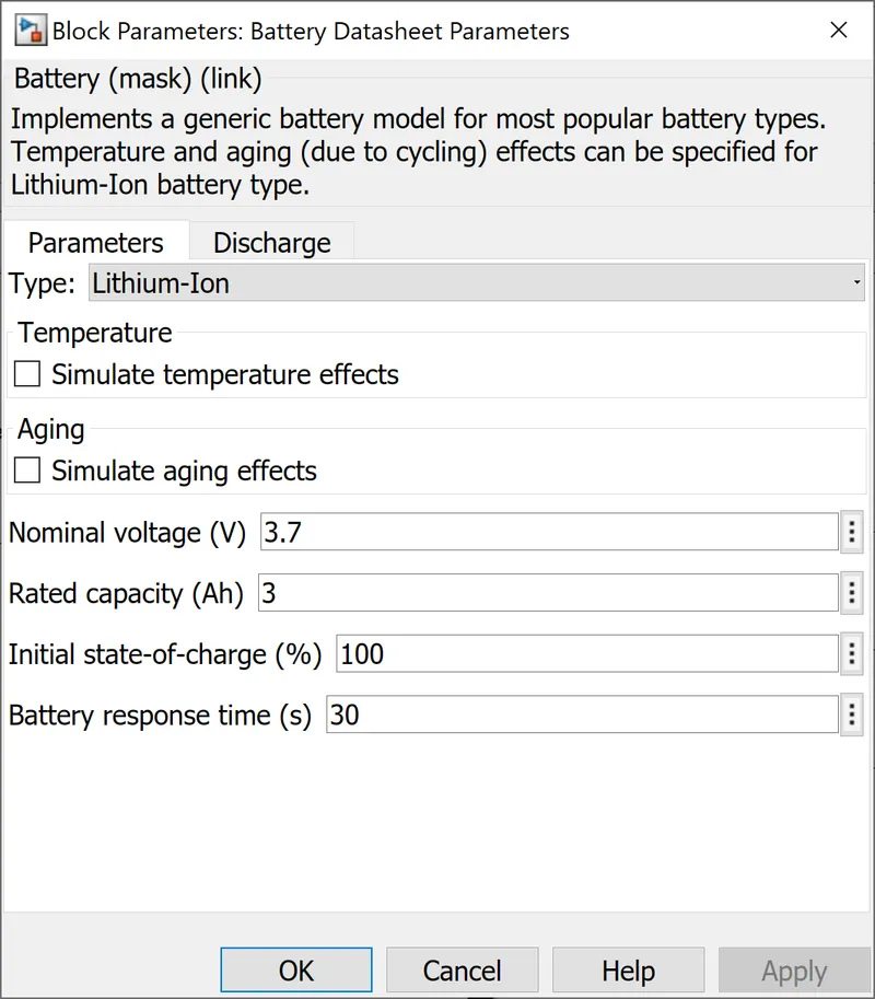
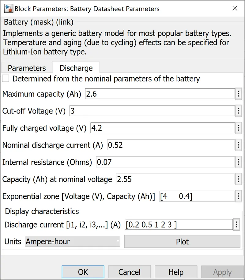
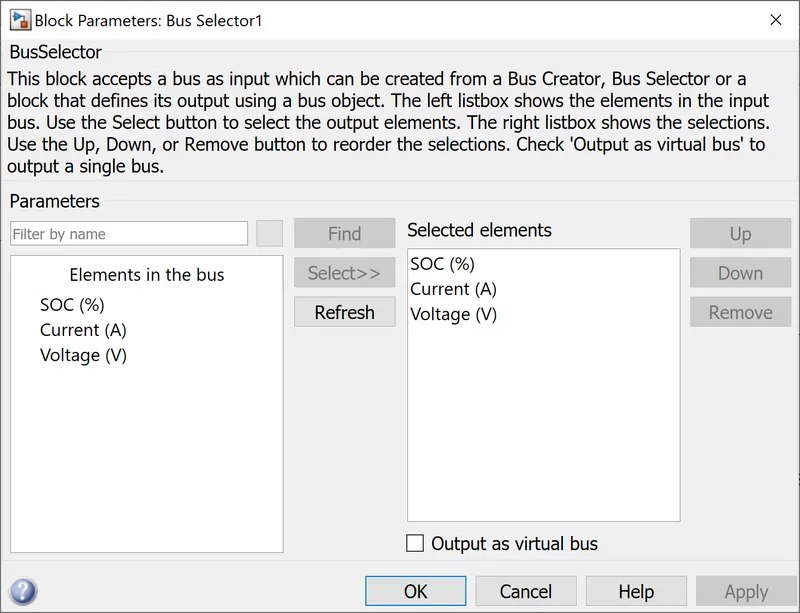
For the case of default battery, the values were not changed and was left with default values. - Bus Selector: This block accepts a bus as input, which can be created by a Bus Creator, Bus Selector, or a block whose output is defined by a bus object. The signals on the input bus are displayed in the left listbox. To select the output signals, press the Select button. The choices are displayed in the right listbox. To reorder the options, use the Up, Down, or Remove buttons. To output a single bus signal, select 'Output as virtual bus'.
- Powergui: The powergui block allows you to solve your circuit using one of the following methods:
- Continuous, which employs a Simulink variable-step solver
- Discretization of the electrical system in order to arrive at a solution in fixed time steps.
The powergui block also provides access to tools for analysing steady-state and simulation results, as well as advanced parameter design. To simulate any Simulink model containing Simscape Electrical Specialized Power Systems blocks, the powergui block is required. It saves the equivalent Simulink circuit that represents the model's state-space equations.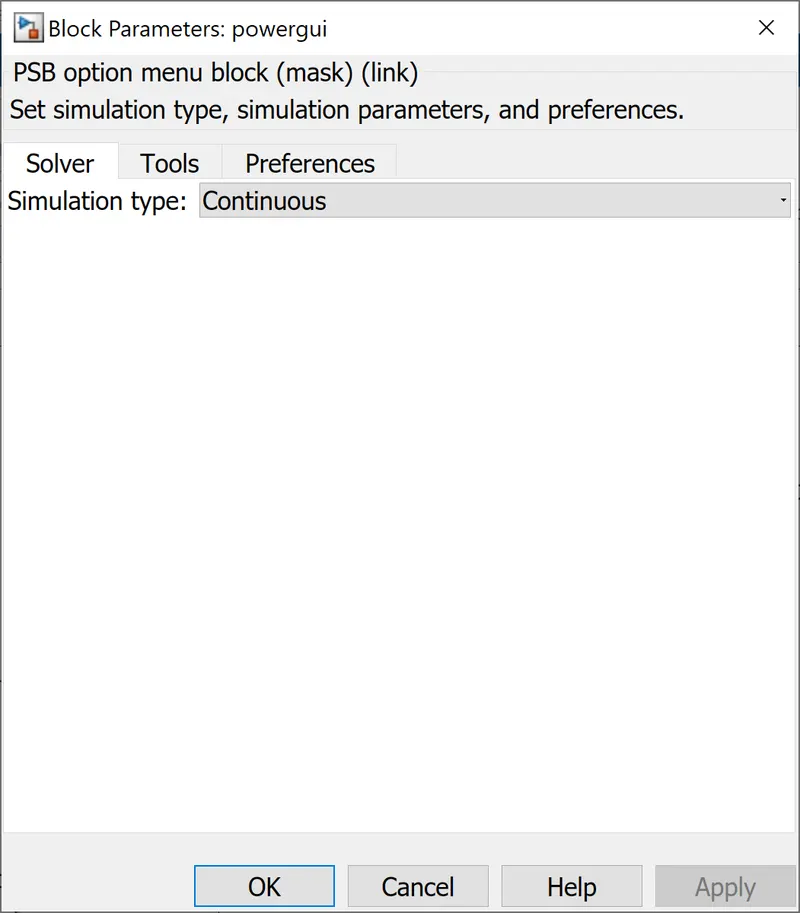
- Scope: The scope block is to display the signals.
The UDDS drive cycle data is generated using the signal builder block. This block's main disadvantage is that it only accepts data in the form of the current profile. As a result, the speed vs time data from the UDDS drive cycle data was converted to current vs time data. The data is then imported into the block via an excel file.
The signal builder's output is sent to the current-controlled source, which is connected to the battery as a load. As a result, the battery discharges in accordance with the signal provided by the signal builder, which is the UDDS drive cycle data.
The Powergui block is required for Simulink models containing SimPowerSystems blocks to be simulated. It is used to save the equivalent Simulink circuit that represents the model's state-space equations.
A bus selector routes the battery's output to the scope. The bus selector sends the battery signals (voltage, current, and state of charge) to the scope.
Output of the Simulink Model:
- Rate Discharge Characteristics:
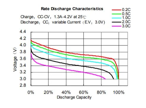
The datasheet provides the Rate Discharge Characteristics as shown above. The same characteristics are compared with the help of the plot function of the battery parameter window and the result is as shown below: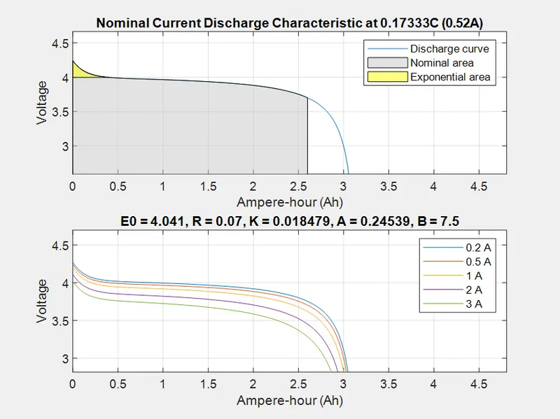
As seen in the plot, the result characteristics correspond exactly to the datasheet provided here. The nominal and exponential areas are easily distinguished from the discharge curves. This battery has a maximum capacity of 2.6Ah and a standard discharge current rate of 0.52A, making it a 0.2C rate capable of running for 5 hours at 0.52A. That would imply that the battery should be able to run at 2.6A for one hour. However, due to the internal resistance and heat generated by the battery when it has to supply a higher current, this is not possible in practise due to Peukert's law. If the battery was discharged at a 1C rate, i.e. 2.6A, it would almost certainly last less than an hour due to reduced capacity. According to the datasheet's discharge curves, when the battery is discharged at 7.8A or 3C, the capacity drops to about 85%, or from 2.6Ah to >2.2Ah. Furthermore, according to Peukert's law, the battery should not be able to operate for 20 minutes at 7.8A. However, the curves shown above show that the capacity has only decreased from 2.6Ah to >2.53Ah, and it will also run for 20 minutes at 7.8A, which should not be the case.
As a result, this implies that the MATLAB/SIMULINK built-in battery model does not account for Peukert's law and that the internal resistance of the battery does not vary with the amplitude of the current.
The same thing is observed with the block's default battery parameter, which exhibits the same type of behaviour; things are happening, but the values are different, as shown below.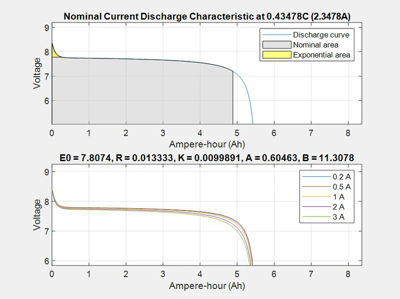
Both results show that the higher the C-rating used for battery discharge, the lower the time capacity to deliver power, i.e. the higher the C-rate discharge current, the lower the battery life. - Output Voltage, Current, SOC Graph:
Datasheet Lithium-Ion Battery Parameters Scope Output: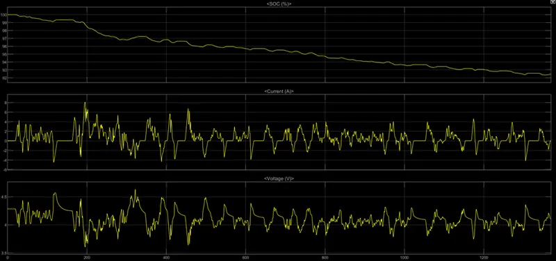
Datasheet Lithium-Ion Battery Parameters Scope Output: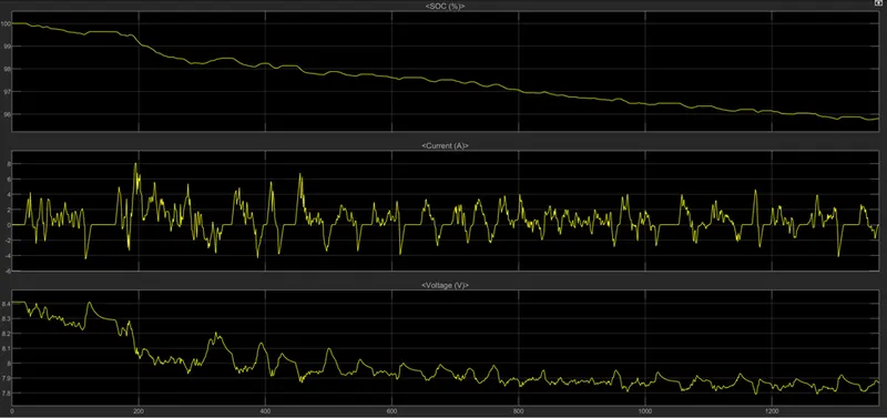
The voltage is quickly falling from its maximum value Simulated with the default lithium-ion battery parameters of nominal value and then slowly decreasing as per the requirements of the UDDS drive cycle data, as shown by both output results of the Voltage-Current-SOC graph. The voltage rise occurs because regenerative braking is taking place at that time, and the battery is being charged, causing the voltage to rise briefly. The second row of the output result shows the current drawn from the battery. The section with the negative current is essentially the regenerative braking portion, where the battery is charged by braking with the car paddle.
Conclusion:
From datasheet of a lithium ion battery, the generic battery model was configured in MATLAB and it was successfully simulatedusing UDDS data.
References:
- https://www.ineltro.ch/media/downloads/SAAItem/45/45958/36e3e7f3-2049-4adb-a2a7-79c654d92915.pdf
- https://en.wikipedia.org/wiki/Lithium-ion_battery
- https://kuscholarworks.ku.edu/bitstream/handle/1808/27598/Moradi_ku_0099M_15757_DATA_1.pdf?isAllowed=y&sequence=1
- https://www.mathworks.com/solutions/power-electronics-control/battery-models.html
- https://www.mathworks.com/help/sps/powersys/ref/battery.html;jsessionid=d21519b5ddaddc4238d3dbb4943b