ANSYS Project: Stress Concentration on a Plate with hole
Aim:
To perform static analysis on the two models of a rectangular plate with a single hole and multi-holes.
Theory:
Stress concentration
A stress concentration is a spot in a solid object where the tension is much higher than the surrounding region. Stress concentrations develop when imperfections in the geometry or substance of a structural component disrupt the passage of stress. This is caused by features such as holes, grooves, notches, and fillets. Accidental damage, such as nicks and scratches, can also cause stress concentrations.
A stress concentration factor (Kt) is a dimensionless factor that quantifies the concentration of stress in a mechanical component. It is defined as the ratio of the part's peak stress to a reference stress.
A stress concentration, also known as a stress riser/raiser, is a location in a body where the stress is much higher than in the surrounding region. Stress concentrations develop as a result of abnormalities in the geometry or material of a component structure that disrupt the stress flow. These breaks are often caused by discontinuities such as holes, grooves, notches, and fillets. Accidental damage, such as nicks and scratches, can also cause stress concentrations.
Under normal tensile stresses, the degree of concentration of a discontinuity is commonly described by the non-dimensional stress concentration factor (Kt), which is the ratio of the maximum stress to the reference (far field) stress:
`K_t=sigma_"max"/sigma_0=T_"max"/T_0`
Where `sigma_0` and `T_0` are stresses determined by elementary equations and `sigma_"max"` and `T_"max"` are localized stresses at the discontinuities. The subscript `t` denotes the theoretical stress concentration factor. The magnitude of the stress concentration factor depends upon the geometry of the component.
The causes of stress concentration are
- Variation in Properties of Materials
- Load Application
- Abrupt Changes in Section
- Discontinuities in the Component
- Machining Scratches
Methods to reduce stress concentration :
Although stress concentration cannot be totally eliminated, there are strategies for reducing stress concentrations. This is accomplished by giving the component a specified geometric form. There are many approaches for reducing stress concentration and bending of the stress lines at the junction. In practice, reduction of stress concentration is achieved by the following methods:
- Additional Notches and Holes in Tension Member
- Providing Fillet Radius, Undercutting, and Notch for Member in Bending
- Drilling Additional Holes for Shaft
- Reducing shank diameter in Threaded Members
Objectives:
- Design a Plate with a Hole and a Plate with three Holes models in Spaceclaim as per the required dimensions.
- Apply Boundary Conditions (fixed support at one end and force of 500N on the other end) and simulate both the designed CAD models.
- Determine Total Deformation and Maximum Stress results for the performed simulations and compare the results for the same.
Case 1: Plate with one hole at the center
The static structural analysis for Case 1 is performed on a plate with a single hole of dimension 60 mm. The material is structural steel, and the analysis is done in ANSYS Workbench. The plate is first modelled in ANSYS Spaceclaim software and is shown in the Figure below: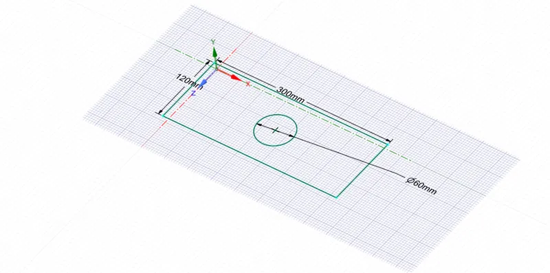
The dimensions of the plate are as follows:
| Length | 300 mm |
| Breadth | 120 mm |
| Thickness | 30 mm |
| Hole Diameter | 60 mm |
The 2D geometry is then extruded inside Spaceclaim in order to load the model into ANSYS Mechanical. The extruded model is shown in Figure below: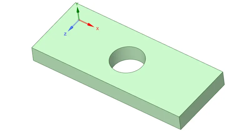
The properties of the material used are as follows:
| Density | 7.85e-06 kg/mm³ |
| Isotropic Secant Coefficient of Thermal Expansion | 1.2e-05 1/°C |
| Young's Modulus | 2e+05 MPa |
| Poisson's Ratio | 0.3 |
| Bulk Modulus | 1.6667e+05 MPa |
| Shear Modulus | 76923 MPa |
| Tensile Ultimate Strength | 460 MPa |
| Tensile Yield Strength | 250 MPa |
The model is meshed using ANSYS Mesher with an element size of 3 mm and a Patch conforming method using Tetrahedrons was employed. This is done to get the best refinement.

A mesh metric was used to identify elements based on their quality, and it can be observed that the elements of the lowest quality are minimum. The majority of the elements have very high quality values ranging from 0.17845 to 0.99861. As a result, the mesh is of adequate quality. The meshed model is as shown in image below: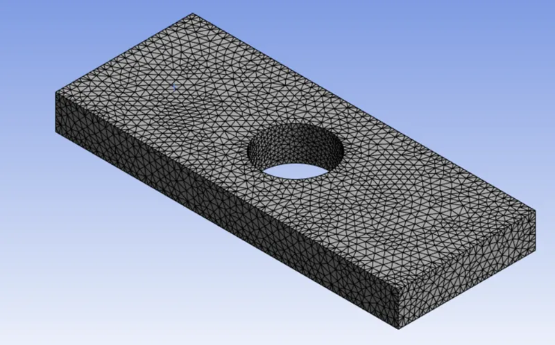
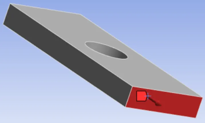
The boundary conditions are then applied as shown below. On the one end, a fixed support is provided and on the other side a force of 500N (tensile) is then applied.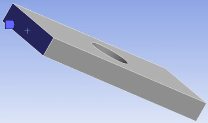
Case 2: Plate with Multiple Holes
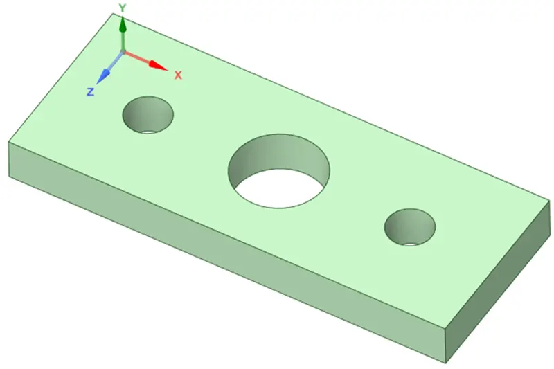
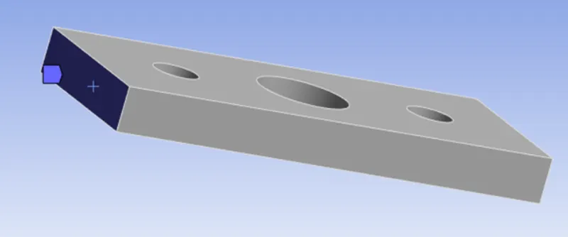
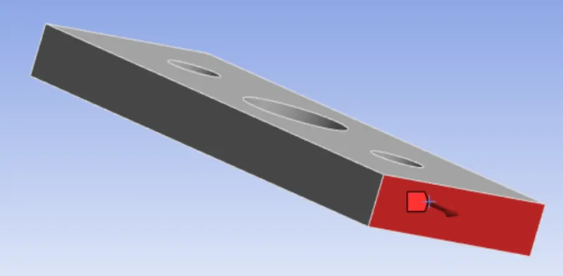
For case 2, Static Stuctural Analysis is carried out on a plate with 3 holes. It is a modification of the model used in Case 1 such that there are 2 extra holes of 30mm diameter placed 90mm away from the centre. The dimensions of the plate and the material used are the same as in case 1. The 2D and 3D model of the plate is shown in the Figure below: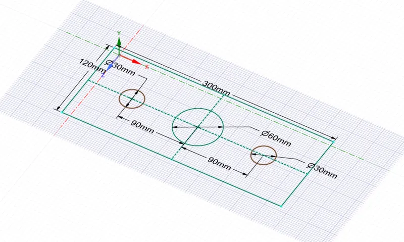
The model is meshed using ANSYS mesher. An element size of 3 mm is applied and a Patch conforming method using tetrahedrons was implemented.

A mesh matric that identifies elements accordin to their quality was employed and it can be seen that the elements of lowest are minimal. Most of the elements have very high quality in the range of 0.13032 to 0.99889. Hence, the mesh is of acceptable quality. The meshed model is shown below: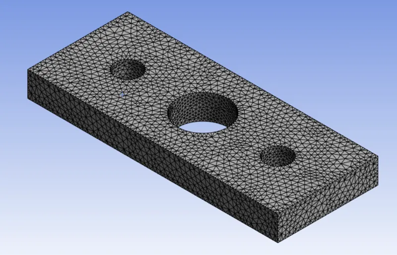
The boundary conditions are then applied as shown below. On the one end, a fixed support is provided and on the other side a force of 500N (tensile) is then applied.
Results:
The deformation and the maximum stress for the both the cases are summerized below:
| Maximum Stress | Average Stress | Maximum Deformation | Average Deformation | |
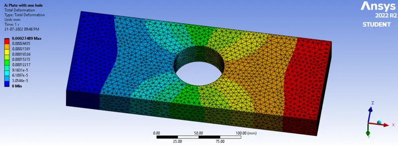
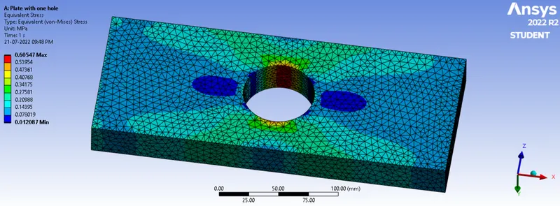
| Case 1 | 0.60547 MPa | 0.1718 MPa | 2.7489e-004 mm | 1.3895e-004 mm |
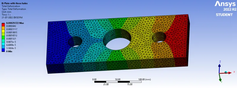
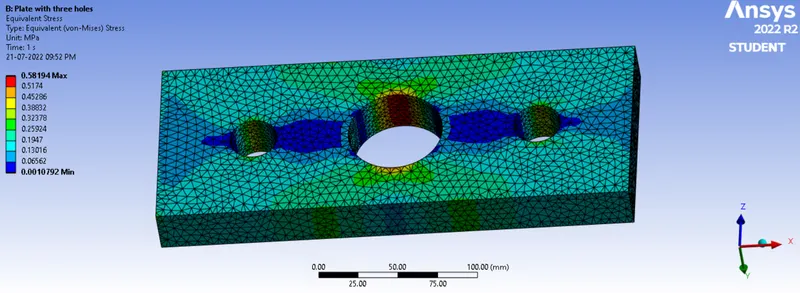
| Case 2 | 0.58194 MPa | 0.16929 MPa | 2.9722e-004 mm | 1.4617e-004 mm |
Case 1: Plate with a Hole
- Deformation
- Stress Concentration:
Case 2: Plate with Multiple Holes
- Deformation
- Stress Concentration
Animations:
Case 1: Plate with a hole
- Deformation
- Equivalent Stress
Case 2: Plate with Multiple Holes
- Deformation
- Equivalent Stress
Conclusion:
The study was completed successfully, and the simulation findings for the two scenarios were analyzed. Despite the fact that case 2 had further geometrical differences, the mesh size for both cases was set to the same value. Less material was required in instance 2 due to the existence of two more holes. This enables for a smaller number of components while maintaining the same mesh size.
There is just a tiny variation in the average (0.2275e-004 mm) and maximum (0.0722e-004 mm) deformation experienced by the model in the two scenarios, with case 2 having the greater value.
When the Equivalent Stress experienced by the model in the two situations is compared, there is a difference in the average (0.00251 MPa) and highest (0.02353 MPa) stress value. However, the maximum and minimum levels of stress experienced in Case 2 are lower than in Case 1.
As a result of these findings, Case 2 may be selected from analysis point of view since the stress experienced by it when the same amount of tensile force is applied is less than that of its counterpart, and the difference in deformation values is also quite modest.
Case 1 can be chosen from the standpoint of manufacturing since the work that has to be done on the model is less when compared to Case 1 and there is not much gain in performance when the work done to manufacture the model is considered.