ANSYS Project: Spur Gear [Static Structural Analysis]
Aim:
To perform static analysis on the Spur Gear mechanism for three different materials Cast Iron (ductile), Cast Steel and Cast Bronze.
Theory:
Spur Gear
The simplest kind of gears are spur gears or straight-cut gears. They are made up of a disk or cylinder with radially projecting teeth. To ensure a constant driving ratio, the cross section's sides are curved rather than straight. Spur gears may only be installed on parallel shafts for proper meshing. The tooth loads do not produce any axial thrust. Spur gears perform admirably at medium speeds but are typically loud at high speeds.
Spur gears go into one of two major categories: internal or external. "External gears" are gears that have teeth that protrude from the cylinder's outside. "Internal gears" are gears having teeth on the inside of the cylinder. An internal gear or an exterior gear may mesh with one another. Two external gears rotate in opposing directions when they mesh. Only when the gears spin in the same direction can an internal gear mesh with an exterior gear. Internal gear assemblies are smaller than exterior gear assemblies because the shafts are positioned closely together.
Stress concentration
A stress concentration is a spot in a solid object where the tension is much higher than the surrounding region. Stress concentrations develop when imperfections in the geometry or substance of a structural component disrupt the passage of stress. This is caused by features such as holes, grooves, notches, and fillets. Accidental damage, such as nicks and scratches, can also cause stress concentrations.
A stress concentration factor (`K_t`) is a dimensionless factor that quantifies the concentration of stress in a mechanical component. It is defined as the ratio of the part's peak stress to a reference stress.
A stress concentration, also known as a stress riser/raiser, is a location in a body where the stress is much higher than in the surrounding region. Stress concentrations develop as a result of abnormalities in the geometry or material of a component structure that disrupt the stress flow. These breaks are often caused by discontinuities such as holes, grooves, notches, and fillets. Accidental damage, such as nicks and scratches, can also cause stress concentrations.
Under normal tensile stresses, the degree of concentration of a discontinuity is commonly described by the non-dimensional stress concentration factor (Kt), which is the ratio of the maximum stress to the reference (far field) stress:
`K_t=σ_"max"/σ_0=T_"max"/T_0`
where `sigma_0` and `T_0`are stresses determined by elementary equations and `sigma_"max"` and `T_"max"`are localized stresses at the discontinuities. The subscript `t` denotes the theoretical stress concentration factor. The magnitude of the stress concentration factor depends upon the geometry of the component.
The causes of stress concentration are
- Variation in Properties of Materials
- Load Application
- Abrupt Changes in Section
- Discontinuities in the Component
- Machining Scratches
Methods to reduce stress concentration :
Although stress concentration cannot be totally eliminated, there are strategies for reducing stress concentrations. This is accomplished by giving the component a specified geometric form. There are many approaches for reducing stress concentration and bending of the stress lines at the junction. In practice, reduction of stress concentration is achieved by the following methods:
- Additional Notches and Holes in Tension Member
- Providing Fillet Radius, Undercutting, and Notch for Member in Bending
- Drilling Additional Holes for Shaft
- Reducing shank diameter in Threaded Members
Objectives:
- Getting ready with the Spur Gear 3D models developed in Solidworks and importing it into the Ansys Workbench for static structural Analysis.
- Apply Boundary Conditions by setting up the contacts and joints. Also editing the analysis setting for the simulation to take place step by step.
- Determine Total Deformation, Equivalent Strain and Maximum Stress results for the performed simulation.
- Repeating the Simulation for other two materials and comparing the solution.
Case Explanation:
A static structural analysis is to be conducted for a spur gear mechanism of three different material. The material refers each case as listed below:
| Case 1: | Cast Iron (Ductile) |
| Case 2: | Cast Steel |
| Case 3: | Cast Bronze |
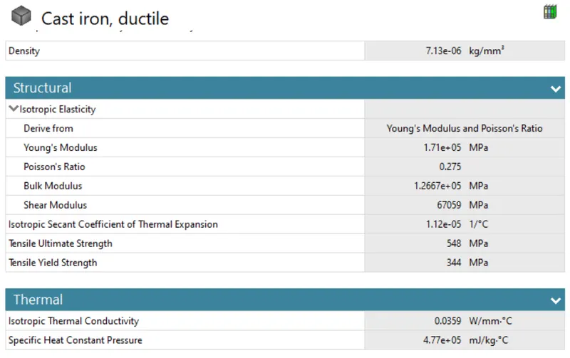
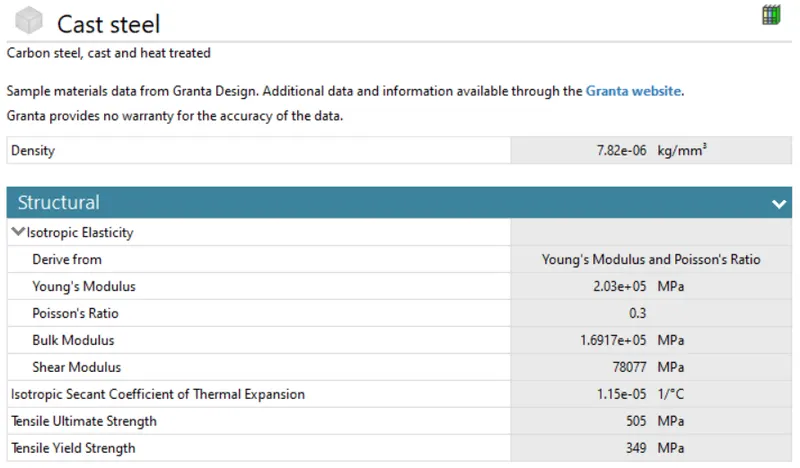
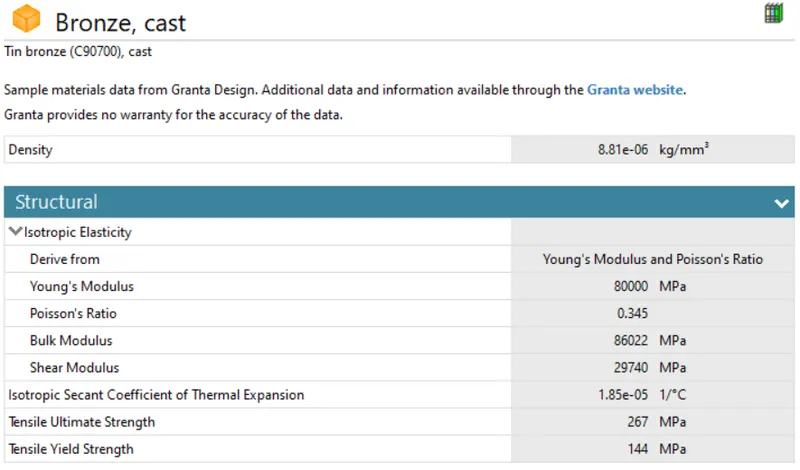
The material property of each material is provided below:
- Case 1: Cast Iron (Ductile)
- Cast Steel
- Bronze Cast
The 3D model of the Spur gear developed in SOLIDWORKS is shown in figure below: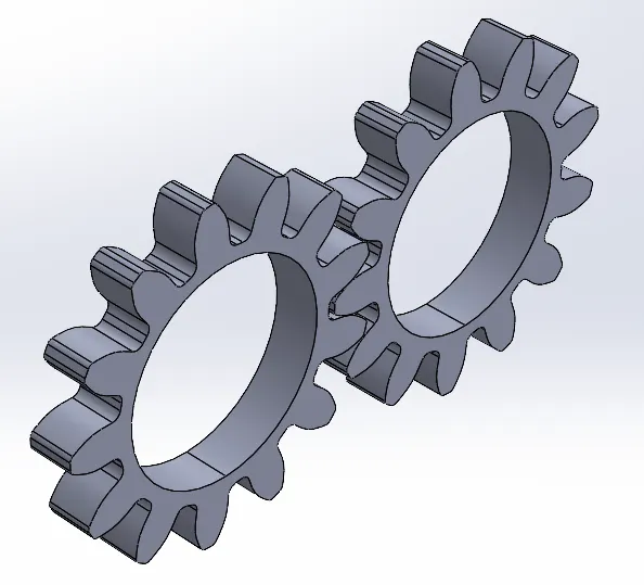
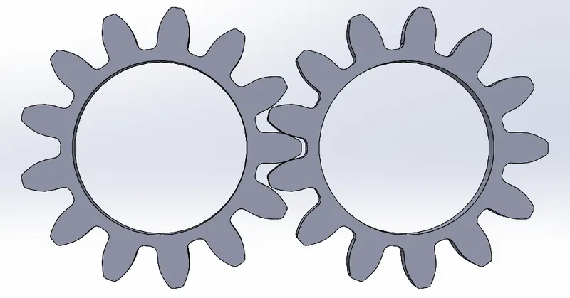
These models are then imported to Ansys Mechanical Static Structural Workbench.
The contacts between the tooths of the two gears were defined as shown in figure below. In order to reduce the time for simulation, the contacts on large side of the tooth were the contact mainly happen was only selected, as seen in figure.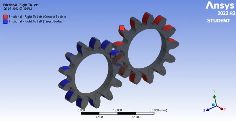
The type of contact selected is frictional and changed the behaviour to symmetric. The Augmented Lagrange formulation was selected in order to avoid the penetration of gear and to provide extra stiffness.
A revolute joint was defined for both gears. Thus, it was created with, connection type as Body-Ground as type of revolute. The inner face of the gear were chosen as scope.
The model is meshed using ANSYS Mesher with an element size of 1 mm and all the parameters are left as default.

A mesh metric was used to identify elements based on their quality, and it can be observed that the elements of the lowest quality are minimum. The majority of the elements have very high quality values ranging from 0.4498 to 0.99942 with an average value of 0.84652. As a result, the mesh is of adequate quality. The meshed model is as shown in image below: 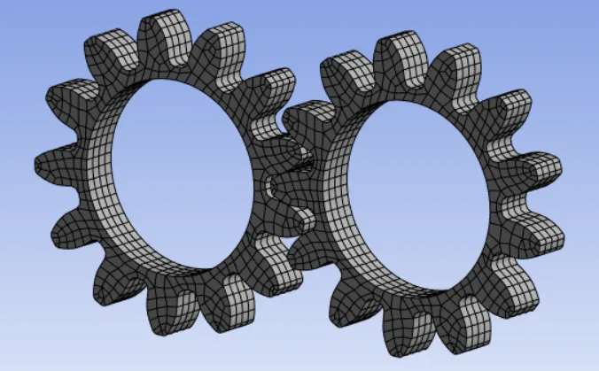
The analysis setting was modified accordingly and number of steps was changed to 6, step end time as 5s, auto time steeping on, define by time, carry over time step as off, intial time step as 0.2s, minimum time step as 5.e-002s, maximum time step as 0.5s. The joint load was then applied to both the gears. The load for the first gear was defined in tabular form as shown below: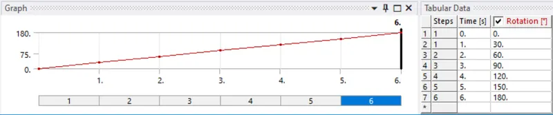
The joint load to the second gear was then given in terms of the moment equalling to 10 N-m or 0.01 N-mm as shown below: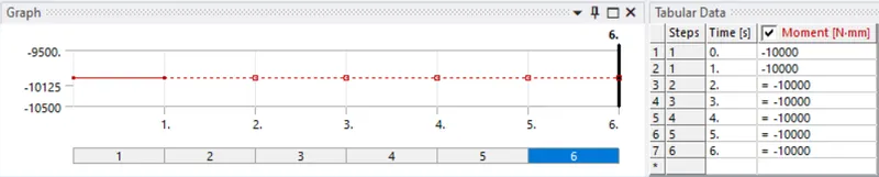
Results:
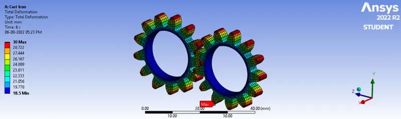
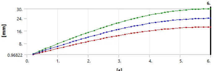
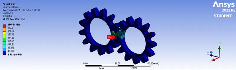
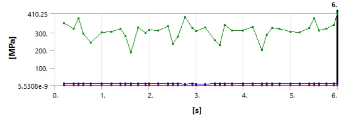
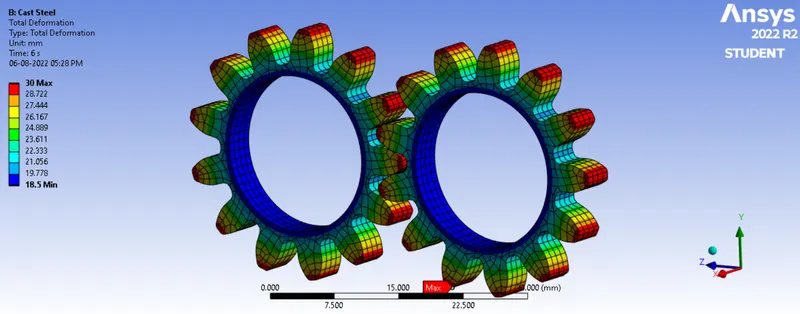
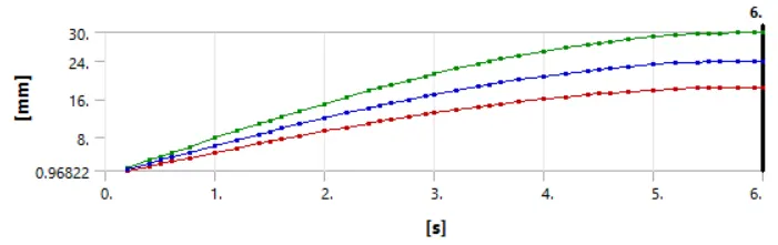
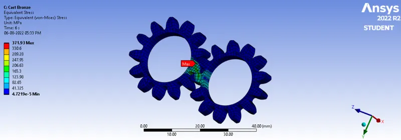
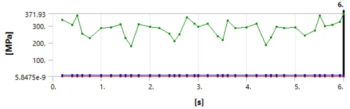
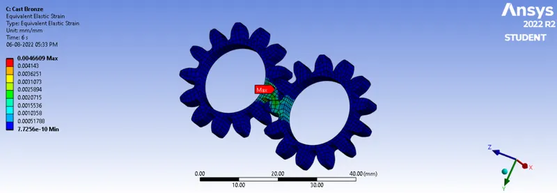
The deformation, Von-Mises stress and Equivalent Elastic Strain for the all the three cases are summerized below:
| Case 1 | Case 2 | Case 3 | |
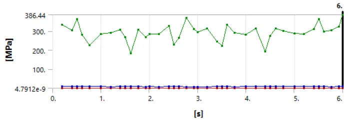
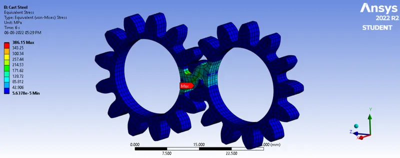
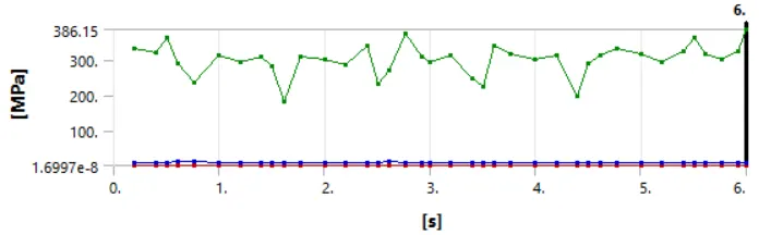
| Maximum Stress | 386.44 MPa | 386.15 MPa | 371.93 MPa |
| Average Stress | 8.2947 MPa | 8.3172 MPa | 8.3041 MPa |
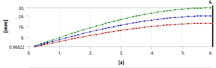
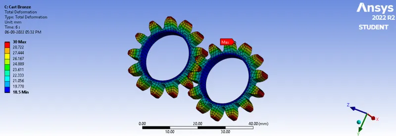
| Maximum Deflection | 30. mm | 30. mm | 30. mm |
| Average Deflection | 23.993 mm | 18.5 mm | 23.993 mm |
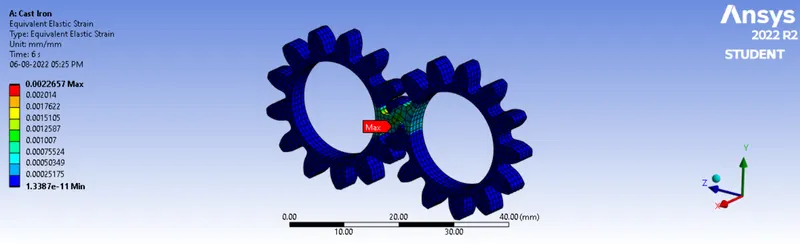
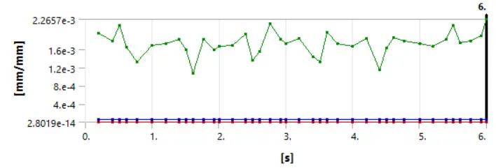
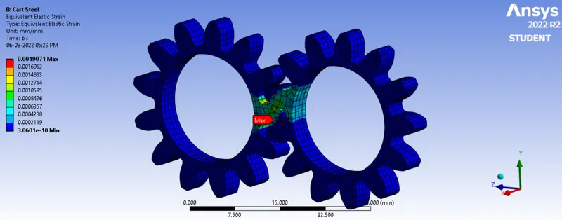
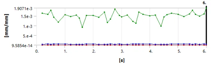
| Maximum Strain | 2.2657e-003 mm/mm | 1.9071e-003 mm/mm | 4.6609e-003 mm/mm |
| Average Strain | 5.3656e-005 mm/mm | 4.5326e-005 mm/mm | 1.1331e-004 mm/mm |
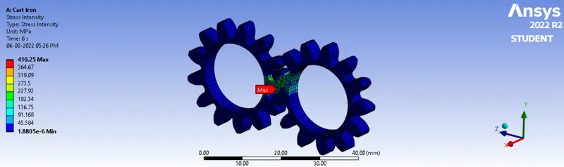
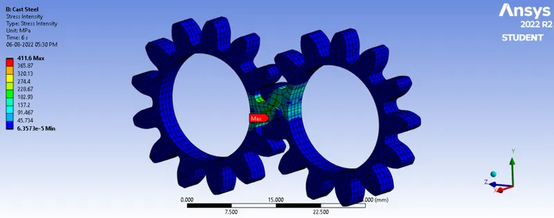
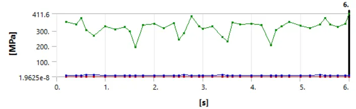
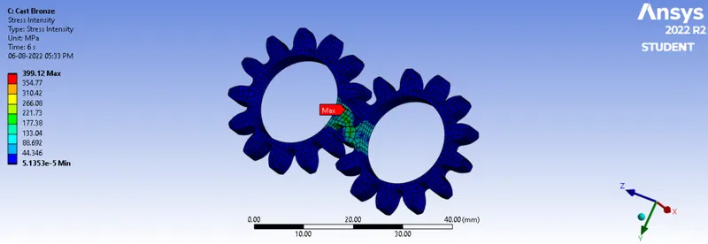
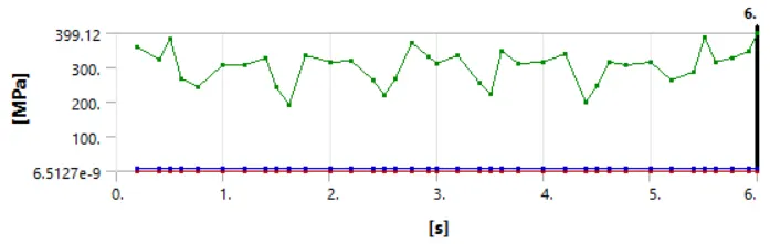
| Maximum Stress Intensity | 411.6 MPa | 410.25 MPa | 399.12 MPa |
| Average Stress Intensity | 8.9966 MPa | 9.0346 MPa | 9.0461 MPa |
Case 1: Cast Iron
- Deformation
- Equivalent Stress
- Equivalent Elastic Strain
- Stress Intensity
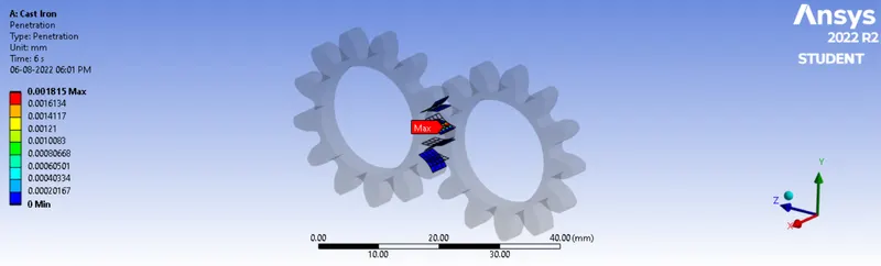
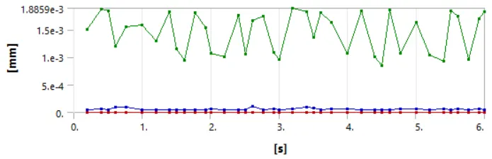
- Contact Tool: Penetration
Case 2: Cast Steel
- Deformation
- Equivalent Stress
- Equivalent Elastic Strain
- Stress Intensity
Case 3: Cast Bronze
- Deformation
- Equivalent Stress
- Equivalent Elastic Strain
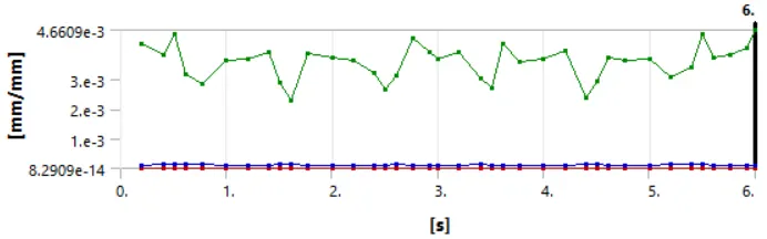
- Stress Intensity
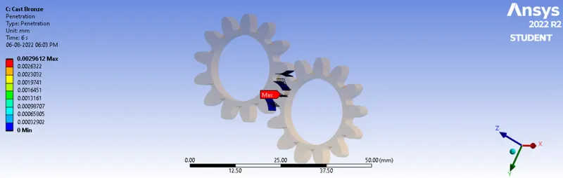
- Contact Tool: Penetration
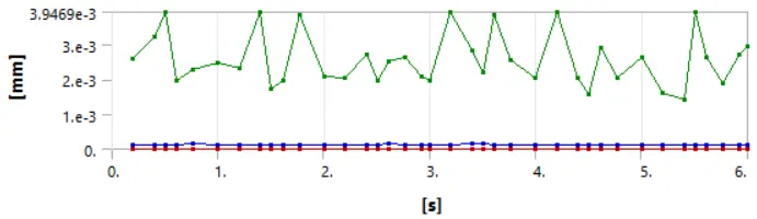
Animations:
Case 1: Cast Iron
- Deformation
- Equivalent Stress
Case 2: Cast Steel
- Deformation
- Equivalent Stress
Case 3: Cast Bronze
- Deformation
- Equivalent Stress
Conclusion:
Three cases for the Spur Gear mechanism made of various materials were compared in this analysis. Cast iron was used in the first case, cast steel in the second, and cast bronze in the third. The deformation is found to be same in all circumstances, but cast iron experiences more stress than the other two, which indicates a higher risk of failure. Now, the fracture mechanics term for the stress concentration close to the crack is the stress intensity. To estimate component failure, it is compared to the critical value or fracture toughness. According to the simulation results, cast iron material has experienced more stress concentration than the other two. A higher level of stress concentration increases the likelihood of failure. Cast bronze material, on the other hand, has demonstrated comparably superior performance against failure. The cast steel stayed between the two at all times.
Therefore, cast steel and cast bronze material should be selected for the production of gears over cast iron from the analyses' point of view.