ANSYS Project: Universal Joint
Aim:
To perform a transient structural analysis of the Universal Joint without contact between the components of mechanism and comparison of different component materials.
Theory:
A universal joint is an attachment that enables relative rotation in two axes between two objects, often shafts. It consists of two revolute joints with intersecting axes that are perpendicular to one another.
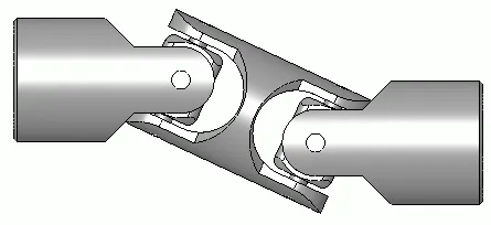
Figure: Universal Joint [WIKIMEDIA, link]
Each shaft finishes in a revolute joint with its axis perpendicular to the shaft's rotational axis when shafts are connected by a universal joint. This permits misalignment in the two remaining rotational degrees of freedom while transferring rotating motion between the shafts. A universal joint has two degrees of freedom since only one rotational degree of freedom (the shaft rotation) is unrestricted (2-DOF).
A constant-velocity joint is not the universal joint. The output shaft's rotation will oscillate if the input shaft rotates at a constant speed. They will both have the same average speed, but the speed of the output shaft will occasionally be higher or lower than this average. The amount of misalignment between the shafts determines how much oscillation occurs in the output shaft; if the shafts are coaxial, the output shaft will really have a constant velocity.
Combining several universal joints can result in a constant velocity joint. A double Cardan joint is a configuration of two universal joints that are 90° out of phase with one another and connected by a short connecting shaft. The two universal joints will cancel out velocity fluctuations such that the final output shaft has a constant velocity if any bend angle is distributed equally across the two joints. However, the intermediate shaft's oscillation will generate vibrations, thus supports are needed to keep the angles equal.
Constant velocity joints are increasingly taking the place of universal joints in automobile drivetrains. Except for some heavy duty off-road vehicles, universal joints are now rarely employed to transfer power to a vehicle's front wheels. Even though constant velocity joints are beginning to be employed for these applications, they are still frequently used for drive shafts. Numerous different mechanical control systems and industrial equipment applications exist for universal joints. Large angles between shafts are possible with universal joints. A flexible coupling can be used instead of a universal joint when there is just a tiny misalignment between the shafts.
Objectives:
- Getting ready with the Universal Joint 3D models developed in Solidworks and importing it into the Ansys Workbench for Transient Analysis.
- Apply Boundary Conditions by setting up the contacts and joints. Also editing the analysis setting for the simulation to take place step by step.
- Determine Total Deformation, Equivalent Stress and Equivalent Elastic Strain results for the performed simulation.
- Conducting the parametric study for other materials for the component with Spring.
- Analyzing the result and developing an inference for the trend shown with material used.
Analysis Setup:
A transient structural analysis is to be conducted for a Universal Joint for three different cases of material for the component with spring: Structural Steel, Titanium Alloy and Stainless Steel. The simulation is aimed at finding the maximum total deformation, equivalent stress and equivalent strain of the whole mechanism for three different material cases and its comparison.
- Geometry:
The 3D assembly model of the Universal Joint mechanism developed in SOLIDWORKS is shown in figure below: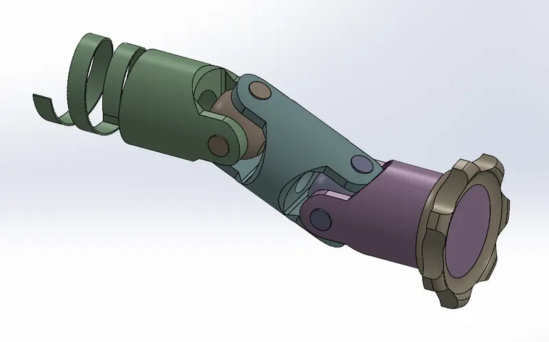
These model is then imported to Ansys Mechanical transient Structural Workbench for the analysis. - Material Properties:
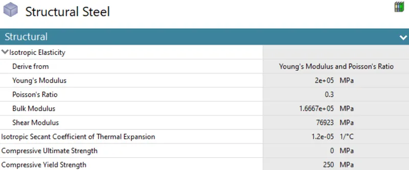
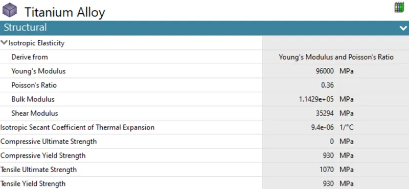
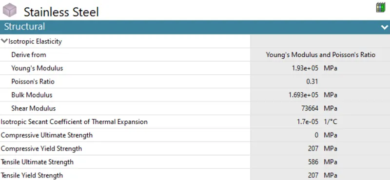
The material of the component with spring is changed for each analysis. This material include Structural Steel, Titanium Alloy and Stainless Steel. All other components are set to be structural steel for all the analysis. The material properties are given below:
- Structural Steel:
- Titanium Alloy:
- Stainless Steel:
- Structural Steel:
- Connection Details:
For this analysis, all the default contact were deleted. This would result in transfer of motion between the components without any loss. This is done since contacts are not the primary concern for this analysis purpose. But multiple joints were established in order to replicate the actual motion of universal joint.
- Contacts:
No contacts were included in the analysis. This would completely transfer the motion between the components of the universal joints. - Joints:
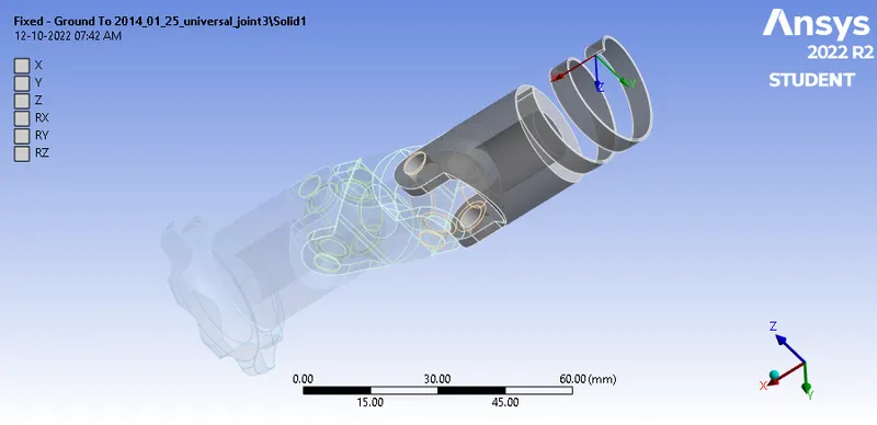
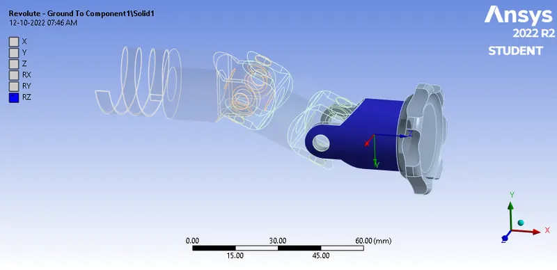
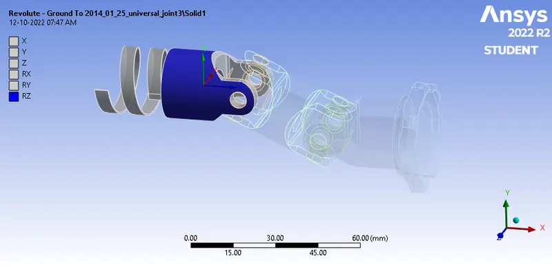
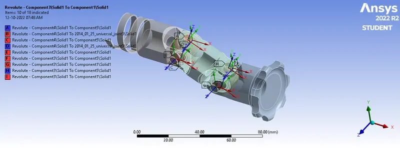
Fixed and Revolute joints are used replicate the universal joint. The fixed joints is used on the Spring where the rotation is to be restricted. The actual rotation is imparted on to the component at the end where body to ground revolution is established. All other revolute joints are of type boby to body as they are relative between the components.
- Fixed Joint:
- Revolute Joint to the first component:
- Revolute Joint to the end component:
- Revolute Joint between other components (body to body)
- Fixed Joint:
- Contacts:
- Meshing:
The whole geometry was meshed with an element size of 4 mm. Also, the adaptive sizing was turned off to get the mesh as required. Additionaly, a face sizing is provided with the element with spring with an element size of 3 mm. The total number of nodes and elements generated are 15116 and 8074 respectively. The generated mesh can be seen below: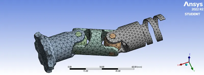

A mesh metric was used to identify elements based on their quality, and it can be observed that the elements of the lowest quality are minimum. The majority of the elements have very high quality values ranging from 6.768e-002 to 0.99931 with an average value of 0.7199. As a result, the mesh is of good quality. - Boundary Conditions:
The simulation was to run for 5 steps. So, the number of steps was assigned as 5. Analysis settings Change no. of steps as 5, Weak spring as program controlled, large deflection on, output controls all as yes, auto time step off and select all steps and provide the time step as 0.1s.
In order to simulate the motion of universal join, the end component was set to revolute for 150 degrees. For that a rotational joint was set up for the analystical purpose as shown below: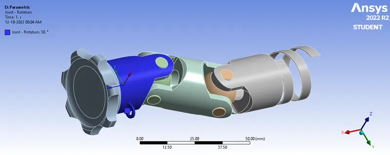

As seen from the above table, the whole 150 degrees rotation was divided between five steps in an equal manner. The co-ordinates were also edited in order to ensure the rotation of Crank along the z direction in the Connection Stage.
Results:
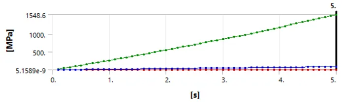
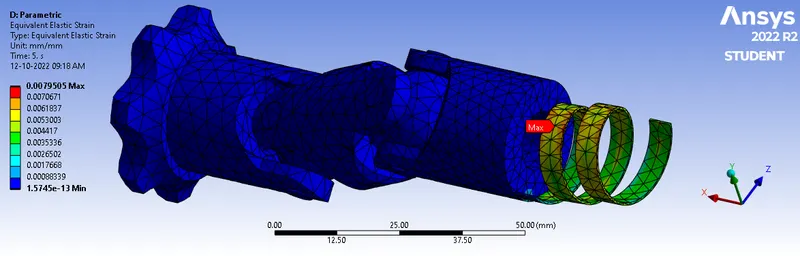
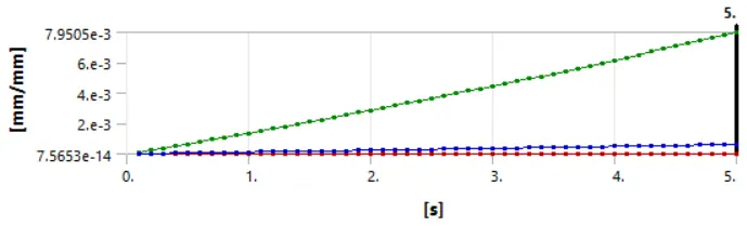
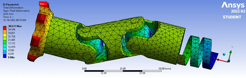
In order to accomodate the comparison of different cases with different material, a parametric study was done which compares the maximum Total Deformation, Maximum Equivalent Stress and Maximum Equivalent Strain.
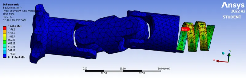
Below provides the observation for the case 1 where the material of the component with the spring is Structural Steel.
- Equivalent Stress:
- Equivalent Strain:
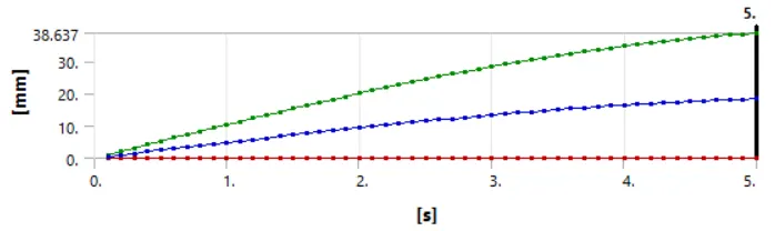
- Total Deformation:
- Animations:
- Equivalent Stress:
- Equivalent Strain:
- Total Deformation:
- Equivalent Stress:
- Comparison:
The observation from the parametric study is as below: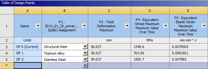
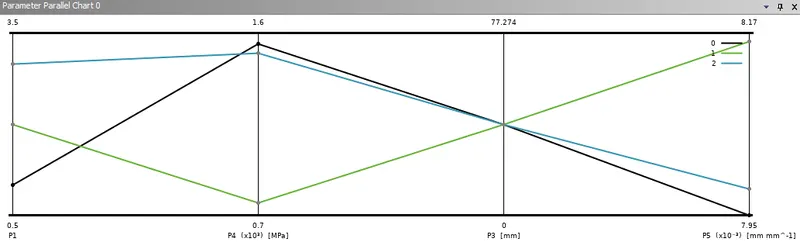
From the above observation, structural steel case has maximum maximum stress bearing capacity and experience the lower the strain among the other case. Due to their weak elastic properties, structural steel and stainless steel are both producing enormous stresses in springs that are far greater than the ultimate tensile stress. Due to its excellent elastic properties, titanium alloy produces stress that is within the yield limit.
The total deformation is seemed to be same for all the cases, this is due to rotational input given which is same for all the three cases.
Therefore, the optimum material for this purpose is titanium alloy since it produces stress that is within its yield limit when loaded. But, Titanium alloy is not economical for common use because it is a very expensive metal.
Conclusion:
With Ansys Workbench, a simulation of a universal joint was conducted while taking into account three different material situations. According to the analysis, titanium alloy produces good structural abilities. Structural steel and stainless steel produce far more stress than their ultimate stress when a rotational force is imposed on a spring. The optimum material for this purpose is titanium alloy since it produces stress that is within its yield limit when loaded. Titanium alloy is not economical for common use because it is a very expensive metal.