ANSYS Project: Bending of an iPhone
Aim:
To perform static structural analysis to simulate the bending of iPhone 6 for two different position of pushing finger cases.
- Case 1: Simulation of the model with pushing fingers in the default position.
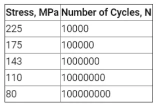
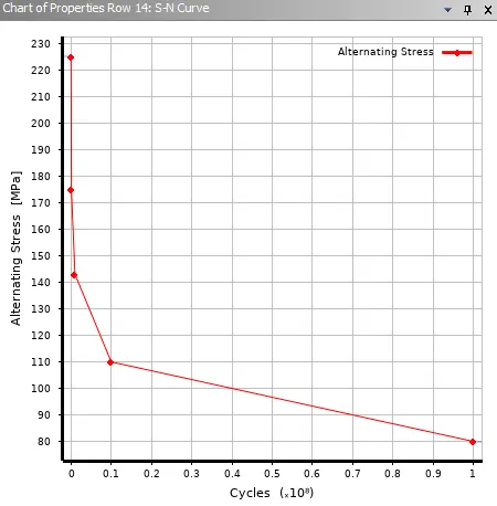
- Case 2: Simulation of the model after moving the bottom fingers from their defined position to the given position X= 22.5mm & Z= 10mm. Also, defining the S-N curve for the Aluminium Alloy material as per values given below:
Theory:
When it was revealed that the iPhone 6, especially the iPhone 6 Plus, bent almost too easily to pressure from nothing more than regular hands, placing them in the back pockets of tight pants, or continuously sitting at different angles, it drew a lot of criticism and jokes.
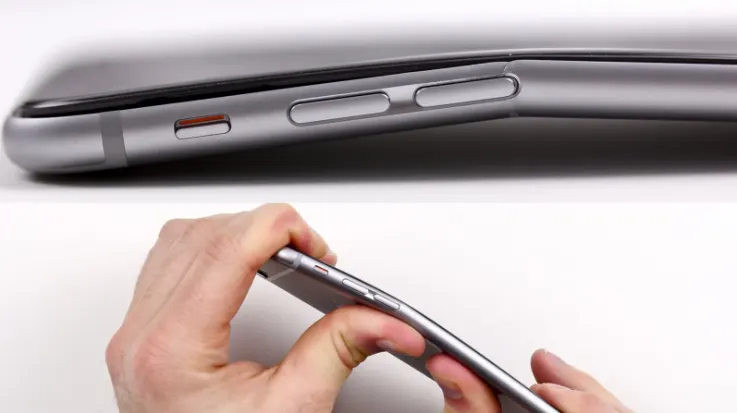
Internal Apple documents have emerged, showing that Apple was aware that the iPhone 6 and 6 Plus phones were more prone to bend than earlier versions. These records were made public by Judge Lucy Koh as part of a case against Apple involving touchscreen failure as a result of bending. Apple continued to deny that there were any bending problems with the iPhone 6. Later, Apple started making internal modifications to the iPhone 6 and 6 Plus designs, including the addition of more epoxy to fortify the region under that chip.
Some people blame it on wearing excessively tight pants, but the underlying problem is with the construction materials. More aluminum is used in the iPhone 6 and 6 plus's chassis than in any other iPhone before. Since aluminum is a naturally soft metal, it will bend with enough force and leverage. Apple allegedly improved the design of the iPhone 6s and 6s Plus by using 7000 Series metal this time.
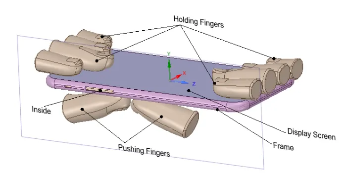
In this project, a model of an iPhone is made to bend using thumb fingers positioned below the volume button in one case, and in the middle of the bottom side of the phone in the other.
Objectives:
- Getting ready with the iPhone Bending 3D models developed in Solidworks and importing it into the Ansys Workbench for static structural Analysis.
- Apply Boundary Conditions by setting up the contacts and joints. Also editing the analysis setting for the simulation to take place step by step.
- Determine Directional Deformation and Equivalent Stress of the complete model for the performed simulation.
- Repeatition of the Analysis for the Case two where additional edit for material and Geometry needed to be done.
- Evaluation of Factor of Safety and Life of the Aluminum Case and comparison of results
Analysis Setup:
A static structural analysis is to be conducted for the iPhone bending setup for two different cases of pushing finger placement. The material of Holding Fingers, Inside, Pushing Fingers, Case, Display Screen and Inside is kept same for bith the cases.
- Geometry
The 3D assembly model of the iPhone bending mechanism developed in SOLIDWORKS is shown in figure below: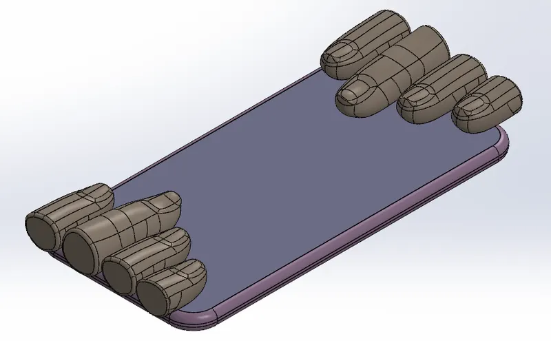
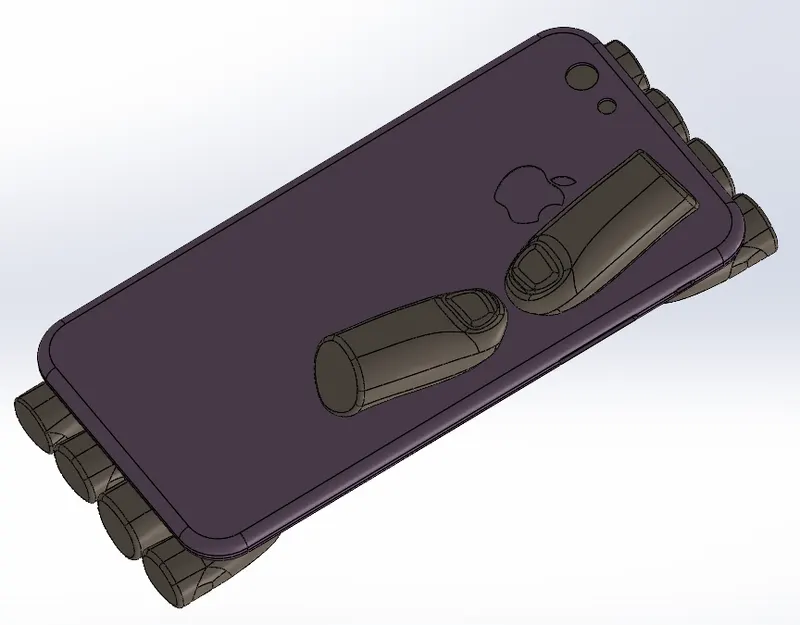
These models are then imported to Ansys Mechanical Static Structural Workbench for the analysis. - Material Properties
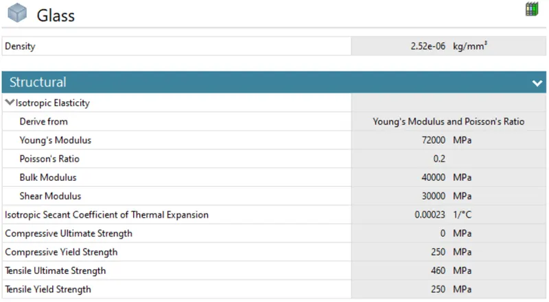
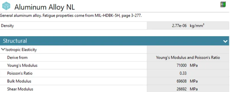
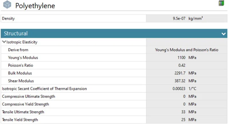
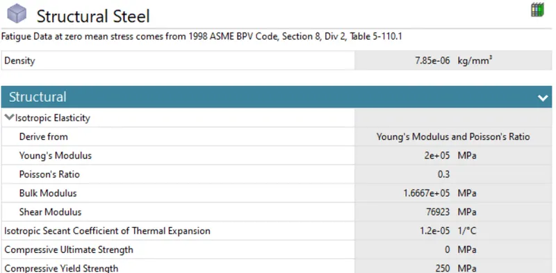
The material of Display was set to be Glass. The frame was allocated the material Aluminum Alloy NL and the Inside was provided with the material Polyethelyne. All the Fingers including the Pushing Fingers were given the default material of Structural Steel. The material properties are given below:
- Glass:
- Aluminum Alloy NL:
- Polyethylene:
- Structural Steel
- Glass:
- Contact Details
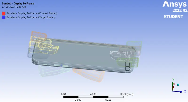
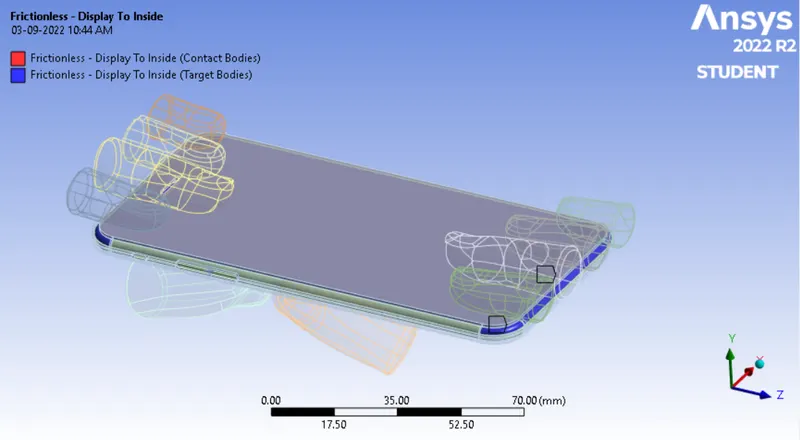
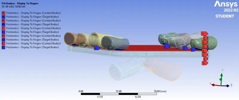
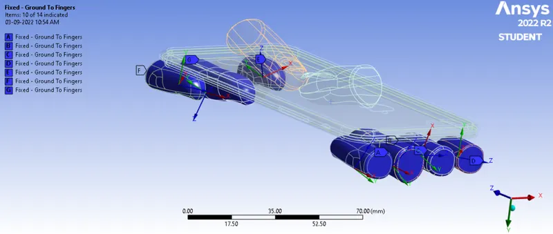
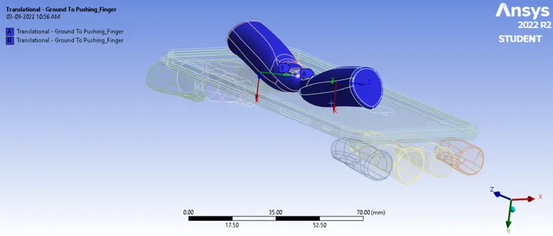
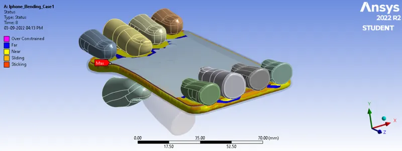
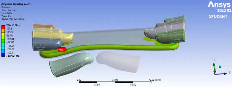
All contacts between the fingers and phone body were defined as frictionless. The contacts between glass to frame and glass to inside were defined as bonded. The pushing fingers were defined as translational joints and all other fingers were defined as fixed joints. The contact inbetween the fingers are not defined as in this simulation it is not required.
- Contact between Dispay and Frame:
- Contact between Display and Inside:
- Contact between Display and Fingers:
- Contact between Frame and Inside:
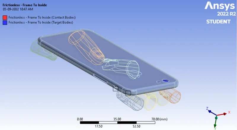
- Contact between Frame and Fingers:
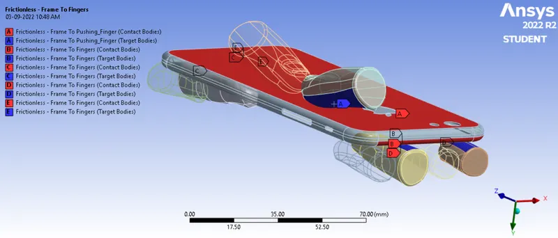
- In joints in order to perform bending action, Fixed joints were provided to the Fingers and a translational motions were provided to the pushing Fingers.
- Joint for Fingers:
- Translational motion for Pushing Fingers:
- Joint for Fingers:
- Contact between Dispay and Frame:
- Meshing
This component is a solid part, tetra mesh can be generated, and to have the accurate result the mesh is refined at the contact regions by giving the face sizing. The mesh formed by default was that of Tetrahedrons. The face sizing is provided in the contact region of Pushing Fingers and Frame with an element size of 4 mm.
The total number of nodes and elements generated are 23017 and 10830 respectively. The generated mesh can be seen below: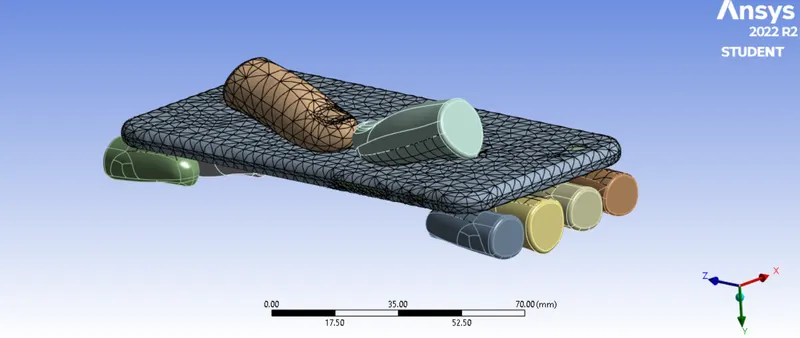

A mesh metric was used to identify elements based on their quality, and it can be observed that the element quality is may not be axcellent. The majority of the elements have very high quality values ranging from 4.1239e-002 to 0.99998 with an average value of 0.37393. As a result, the mesh is of reasonable quality. - Boundary Conditions
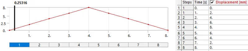
A total of 8 steps are provided to run the simulation. Large deflection set to on, auto time stepping to program controlled, solver type set to direct and stabilization set to constant, method to energy and energy dissipation ratio to 0.1 and in Output control set all output to yes.
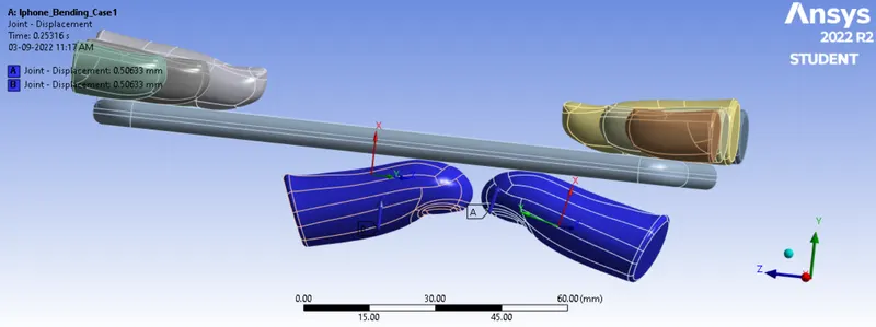
A fixed support is provided to the Inside part at the two edges to smoothen the bending action and restrict the motion of edge of the iPhone. A displacement Joint is provided to the frame as to restrict its motion in the x and z direction by setting the dispacement value to be zero. Also, a displacement joint is provided at the Pushing Fingers as well so as to simulate the motion of the Pushing Fingers.
- Fixed Joint for the Inside Component:
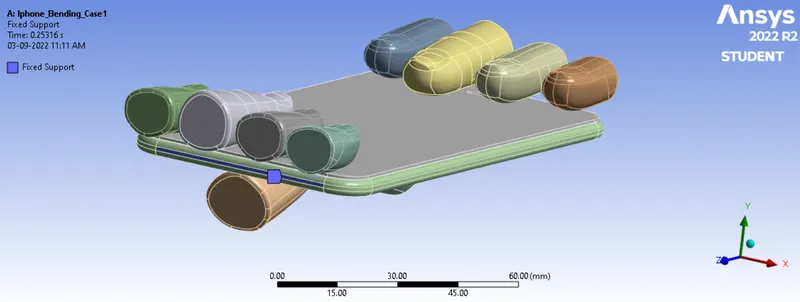
- Displacement Joint for the Frame:
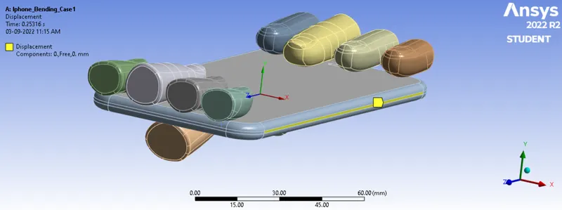
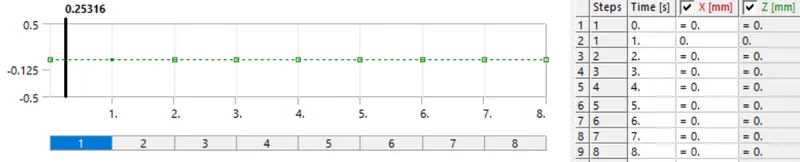
- Displacement Joint for Pushing Fingers:
- Fixed Joint for the Inside Component:
Results:
- Case 1: Simulation of the model with pushing fingers in the default position
The outputs obtained for Case 1 is provided below:
- Directional Deformation of the Model:
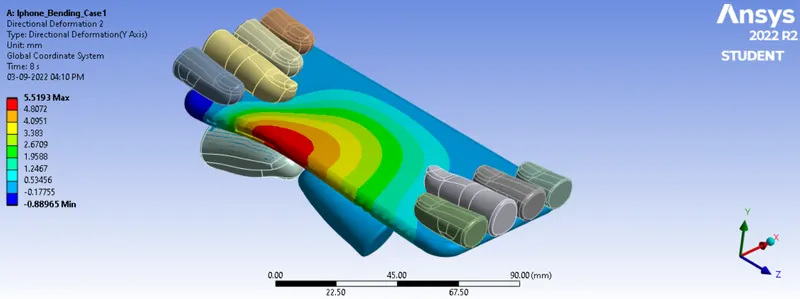
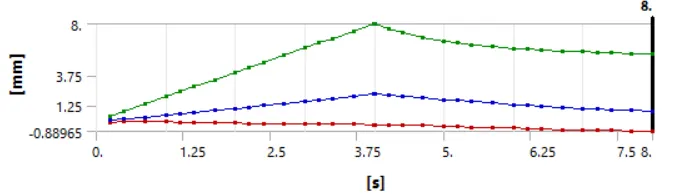
Maximum Deformation = 5.5193 mm
Directional deformation's results are in accordance with the specified displacement boundary condition. The graph depicts the Directional deformation's initial linear growth, which reaches a peak value of about 8 mm. Due to its elastic characteristic, the distorted region thereafter has a tendency to revert to its original state as soon as the loads are removed. During this event, about 2mm of deformation vanished, leaving about 6mm to remain in the component as plastic deformation. - Equivalent Stress of the Model:
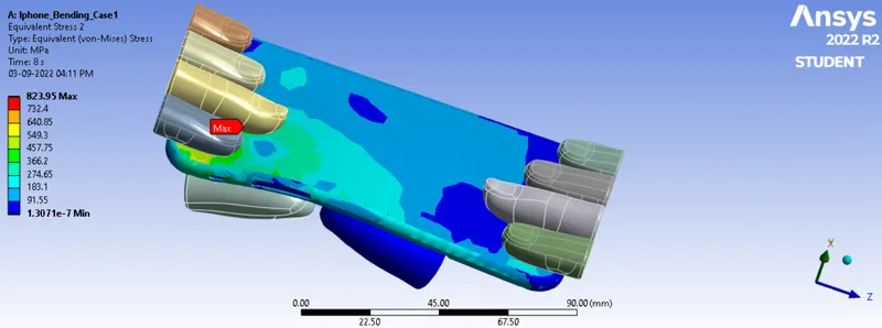
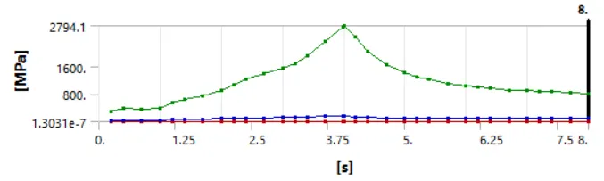
Maximum Equivalent Stress = 604.44 MPa
It can be predicted that there will be some plastic deformation in the Frame because the stress is greater than the yield value of 280 Mpa, which means the complete phone will also bends. - Contact Tool: Status:
- Contact Tool: Pressure
- Animation: Directional Deformation
- Animation: Directional Deformation
- Directional Deformation of the Model:
- Case 2: Simulation of the model after moving the bottom fingers from their defined position to the given position X= 22.5mm & Z= 10mm. Also, defining the S-N curve for the Aluminium Alloy material as per values given below:
The S-N curve for Aluminium Alloy NL material is defined in Material to calculate the outcomes of fatigue life as shown below: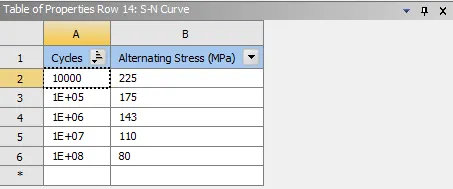
The bottom fingers were moved in Spaceclaim from their defined location to the indicated position of Z=10 mm and X=22.5 mm as shown below: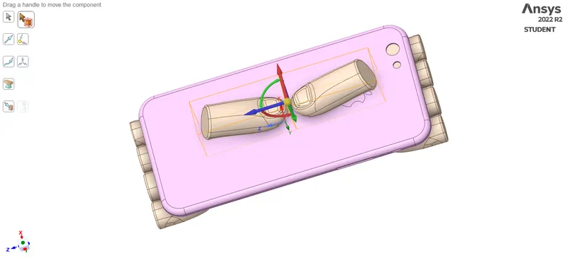
The outputs obtained for Case 2 is provided below:
- Directional Deformation of the Model:
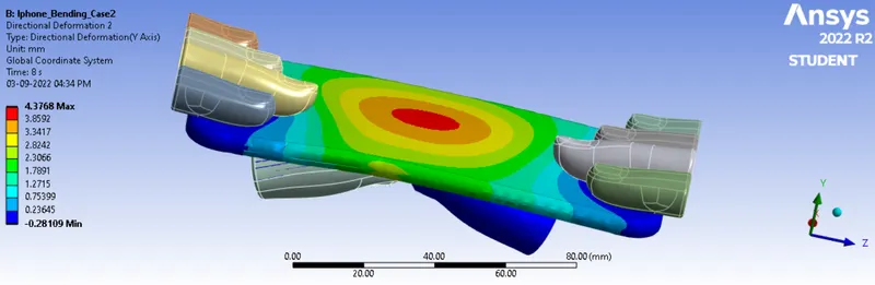
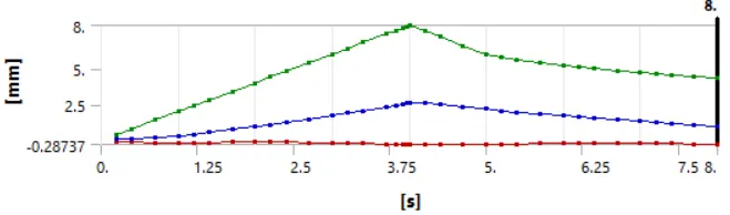
Maximum Deformation = 4.3768 mm
Directional deformation's results are in accordance with the specified displacement boundary condition. The graph depicts the Directional deformation's initial linear growth, which reaches a peak value of about 8 mm. Due to its elastic characteristic, the distorted region thereafter has a tendency to revert to its original state as soon as the loads are removed. During this event, about 2mm of deformation vanished, leaving about 6mm to remain in the component as plastic deformation. - Equivalent Stress of the Model:
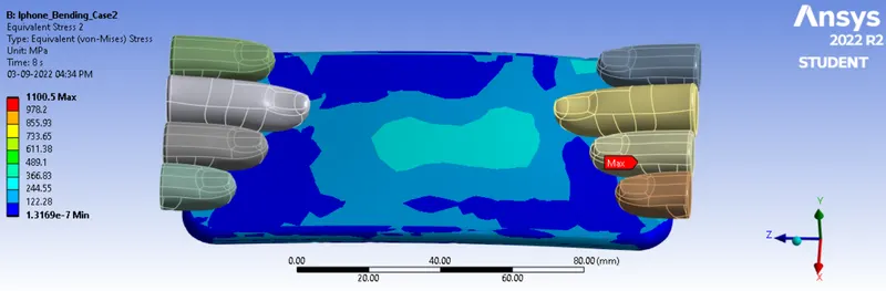
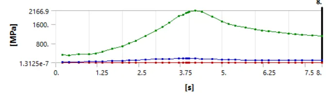
Maximum Equivalent Stress = 1100.5 MPa
Maximum Equivalent Stress on the Frame = 382.37 MPa
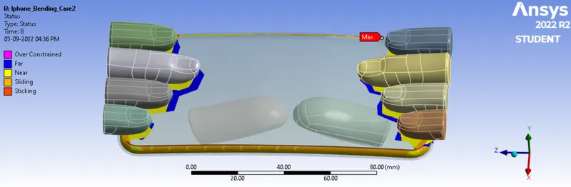
It can be predicted that there will be some plastic deformation in the Frame because the stress is greater than the yield value of 280 Mpa, which means the complete phone will also bends. - Contact Tool: Status
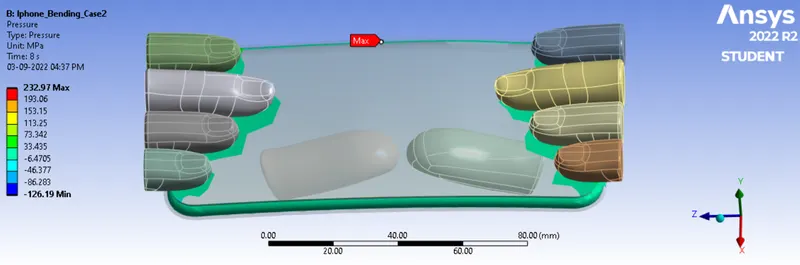
- Contact Tool: Pressure
- Factor of Aluminium Alloy NL
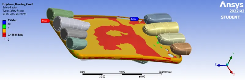
Safety factors come in two different types. Both the Stress Tool and the Fatigue Tool provide one. The Stress Tool Safety Factor determines whether a single load will exceed the limit specified by the case. To determine the safety factor in this case, the provided tensile yield strength is used. The aluminum alloy NL used to make the frame has a 280 Mpa tensile yield strength. Tensile Yield Strength (Frame)/Maximum Equivalent Stress (Frame) equals 280/382.87, which equals 0.7322 for the safety factor.
The load cycles are the basis for the fatigue tool safety factor. Here, for the Analysis type as Stress life and S-N curve is also known. Therefore, the overall Safety Factor is 0.41845 based on the load cycles. From the observation of the safety factors, it is apparent that there is less safety for the Assembly or Frame next to the Side button of the Frame. Crack propagation and failure may begin there. - Life of the Aluminium alloy for the case
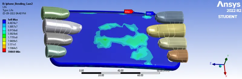
According to the fatigue life results mentioned above, the frame has a minimum lifespan of 70869 cycles. This indicates that the Phone will last up to 70869 cycles at the obtained cyclic loads. Or, at the very least, the area around the side buttons or the minimum life will endure at least 70869 cycles. Then it might crack.
- Animation: Directional Deformation
- Animation: Directional Deformation
- Directional Deformation of the Model:
- Comparison:
- The results of the two cases indicate a similar trend when compared, but when bending action is performed from one of the longitudinal sides, there is more deformation at the conclusion of the eighth time step. This suggests that the first case involved more plastic deformation.
- According to the results of the equivalent stress test, higher strains emerge when a phone is bent from one of its longitudinal sides as opposed to the initial scenario, in which the phone is bent from the center. This is due to the geometric shape of the corner region; when the phone bends from a region close to one side, the moment of area of the geometry increases, which essentially implies more force is needed to bend the phone and more stress is produced as a result.
- Ccomparison of both cases for the Frame:
Case 1 Case 2 Maximum Deformation 5.3506 mm 4.3768 mm Maximum Stress 604.44 MPa 382.37 MPa
According to the comparison table above, Case 2, in which the load is placed at the center, results in almost half as much stress as Case 1. Due to the uniform distribution of the load, Case 2 exhibits less deformation than Case 1. Because the applied load in Case 2 is spread evenly throughout, the resulting force will be lower. Case 1's stress is applied at the side or below the side buttons, which causes more of a one-direction deformation. However, the overall safety factor is below 1, which indicates that even for Case 2, it will fail or is likely to fail.
- The results of the two cases indicate a similar trend when compared, but when bending action is performed from one of the longitudinal sides, there is more deformation at the conclusion of the eighth time step. This suggests that the first case involved more plastic deformation.
Conclusion:
The iPhone with center loading can handle more stress and have a longer lifespan, according to the aforementioned findings. In the early stages of loading, it may bend more if the recurring load is on the sides. iPhone is more durable under center loading conditions than under side loading conditions. In both the circumstances, stress is going beyond the yield limit, which might produce plastic deformations or failure. Therefore, more premium materials should be employed to make the iPhone more robust and to boost strength. The addition of a percentage of zinc to aluminum alloy can also improve composition and increase impact strength. Also, one can keep iPhone in the shirt pocket instead of pant pockets and in a protective case to protect it from bending.