ANSYS Project: Buckle Clip
Aim:
To perform a static structural analysis of the Buckle Clip for two different scenarios:
- Case 1: Moving the buckle by keeping the clip fixed
- Case 2: Moving the clip by keeping the buckle fixed
Theory:
The buckle is a mechanism for securing two loose ends; one end is fastened to it, while the other is secured but adjustable by a catch. The frame, chape, bar, and prong make up the buckle's fundamentally four basic parts. The buckle's frame, which unites its other components, is its most noticeable component. Buckle frames come in a variety of designs, sizes, and forms. The frame's shape could be a simple square or rectangle, but it also could be turned into an oval or a circle. All decorations are placed on the buckle's frame, which is its greatest component. The "end bar" refers to the portion of the frame that the strap passes through before inserting the tongue or prong through the hole. The "central bar" holds the tongue, while the "keeper" or "keeper bar" is the component that, if present, holds the tip of the strap in place. These phrases are used when further details are required to describe a buckle's dimensions or construction.
Figure: Buckle Showing Various Components [reference]
To allow one end of the strap to be fastened before the other, adjustable end, chapes or "caps" of various designs might be attached to the bar. Since buckles were pricey, this resulted in a considerable advantage by making them easily detachable and interchangeable. Steel or other types of metal are often used to make the prong, also known as the pin. The prong in typical belts slides through the buckle to hold the fabric in place at a predetermined length. In America, the prong is frequently referred to as the buckle's tongue, as in "lock-tongued buckle." Only after the tongue is put in place permanently is the prong employed. The bar keeps the chape and prong attached to the frame. The buckle incorporates a moveable bar that is held in position by the tension of the adjusted belt when prongs and chapes are removed from the design.
Side Release Buckle:
A typical snap-fit buckle made up of two buckle members: a "male" buckle member with the hook end and a "female" buckle member with the insertion end. A center rod and two spring prongs that are similarly spaced apart make up the male buckle member. Each of the two spring arms has a retaining block that comes to an end at the front. The two side holes and front open side of the female buckle member are used to grip and secure the two spring arms of the male buckle member. Many strapped items, including pet harnesses, safety harnesses, personal flotation jackets, fanny packs and other bags, belts, gun slings, and boots, can be connected by this type of buckle. Another name for it is the "parachute buckle." They are often used in conjunction with tri-glide slides.
Figure: A buckled side release buckle [reference]
Objectives:
- Getting ready with the Buckle Clip 3D models developed in Solidworks and importing it into the Ansys Workbench for static structural Analysis.
- Apply Boundary Conditions by setting up the contacts and joints for two different cases. Also editing the analysis setting for the simulation to take place step by step.
- Determination of Equivalent Stress, Contact Pressure and Deformations for the performed simulation of each case.
- Analysing the result.
Analysis Setup:
A static structural analysis is to be conducted for the Buckle Clip setup. The material of Buckle Clip is considered to be Polyoxymethylene for the whole analysis.
- Geometry:
The 3D assembly model of the Buckle Clip Setup developed in SOLIDWORKS is as shown in figure below: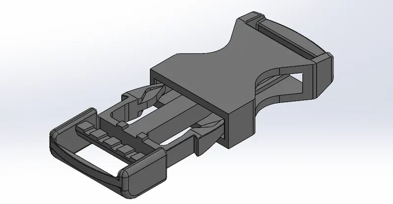
These models are then imported to Ansys Mechanical Static Structural Workbench for the analysis. - Material Properties:
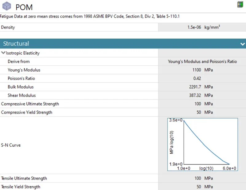
The material of Buckle Clip set to be Polyoxymethylene for all the analysis. This material was unavailable in Ansys material list, therefore, the material properties were manually inserted. The material properties are given below:
- Polyoxymethylene:
- Polyoxymethylene:
- Contact Details:
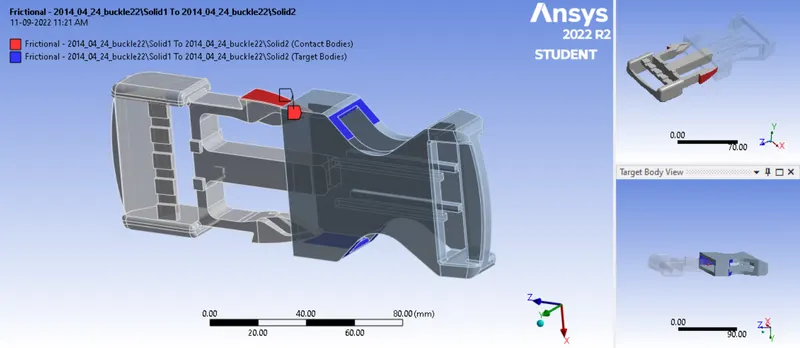
There is only one contact in the entire setup, which has a friction coefficient of 0.2, an Augmented Lagrange formulation, a normal stiffness to factor and a value of 0.1 for the factor, updates stiffness for each iteration, and interface treatment is set to Add offset, Ramped effects.
- Contact between the Clips:
- Contact between the Clips:
- Meshing:
Mesh was created for the buckle clip model so that there are fewer than 31,000 total components. A mesh with an element size of 5 mm was provided. On to it, a face sizing was procided at the contact region for the smooth simulation. An element size of 1.75 mm was allocated onto the 6 faces.
The total number of nodes and elements generated are 29001 and 16122 respectively. The generated mesh can be seen below: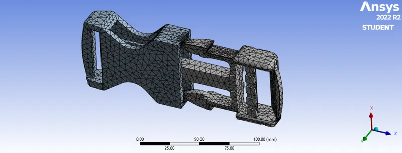

A mesh metric was used to identify elements based on their quality, and it can be observed that the elements of the lowest quality are minimum. The majority of the elements have very high quality values ranging from 1.3549e-002 to 0.99988 with an average value of 0.67984. As a result, the mesh is of reasonable good quality. - Boundary Condition:
There are four steps in the simulation. Therefore, the number of steps is set to 4, solver type and weak springs set as Program controlled, large deflection is turned on, stabilization is set to constant method to energy, the energy dissipation ratio is set to 0.1, and the output control is set to yes for all output.
The motion of the buckle can be simulated two different ways. These two ways are considered as two different cases and the analysis is done separately for these two cases. The two cases are:- Case 1: Moving the buckle by keeping the clip fixed
- Case 2: Moving the clip by keeping the buckle fixed
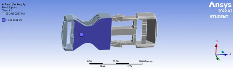
The boundary condition are different for each cases and these cases are discussed separately as below: - Case 1: Moving the buckle by keeping the clip fixed
The buckle provided with fixed support to constrain the movement while the clip is provided with the a displacement along the negative z direction.
- Fixed Support for the Clip:
- Displacement for the Buckle:
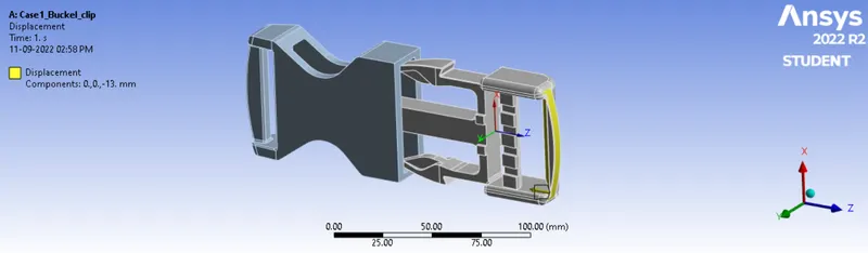

A total displacement of 49.7 mm was provided as four substeps.
- Fixed Support for the Clip:
- Case 2: Moving the clip by keeping the buckle fixed
The Clip is provided with fixed support to constrain the movement while the Buckle is provided with the a displacement along the negative z direction.
- Fixed Support for the Buckle:
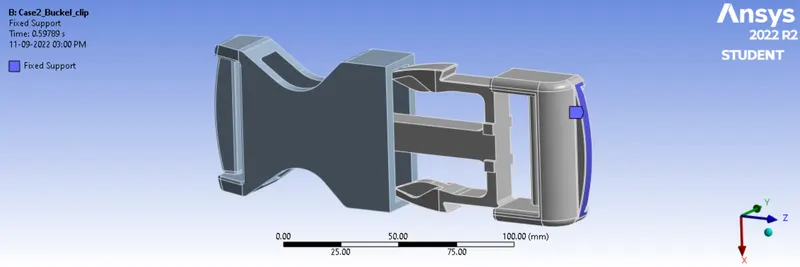
- Displacement for the Clip:
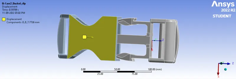

A total displacement of 49.7 mm was provided as four substeps.
- Fixed Support for the Buckle:
Results:
- Case 1: Moving the buckle by keeping the clip fixed
The outputs obtained for Case 1 is provided below:
- Stress generated at the base of the clip
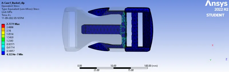
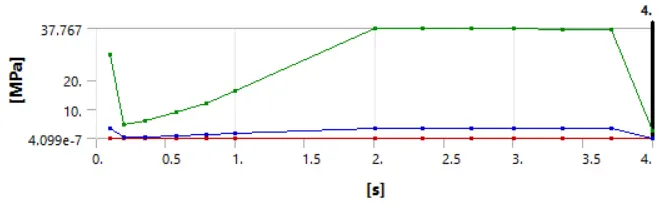
Maximum Stress Occured on Clip at end = 2.7771 MPa
Maximum Stress Occured on Clip over entire time = 37.767 MPa - Contact pressure generated between the outer clip surface and buckle surface
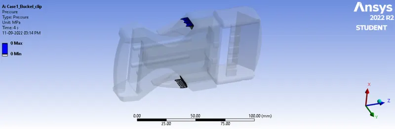
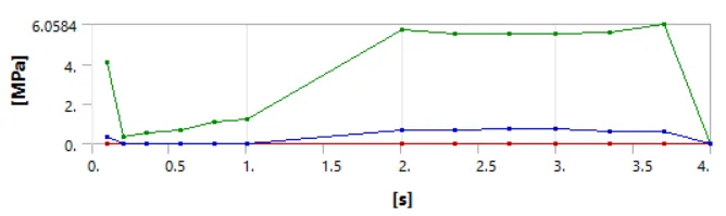
Maximum Contact Pressure over the entire time = 6.0584 MPa - Total deformation of the clip
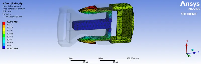
Maximum deformation of 49.745 mm occurs along the z direction (which depicts the motion of clip), while the deforamtion on the along x direction is 9.0174 mm over time. - Animations:
- Equivalent Clip Stress:
- Contact Tool: Pressure
- Total Clip Deformation:
- Equivalent Clip Stress:
- Stress generated at the base of the clip
- Case 2: Moving the clip by keeping the buckle fixed
The outputs obtained for Case 2 is provided below:
- Stress generated at the base of the clip
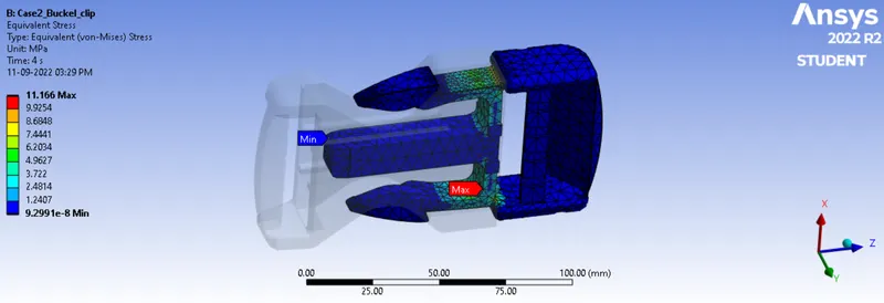
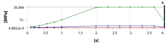
Maximum Stress Occured on Clip at end = 11.166 MPa
Maximum Stress Occured on Clip over entire time = 36.894 MPa - Contact pressure generated between the outer clip surface and buckle surface
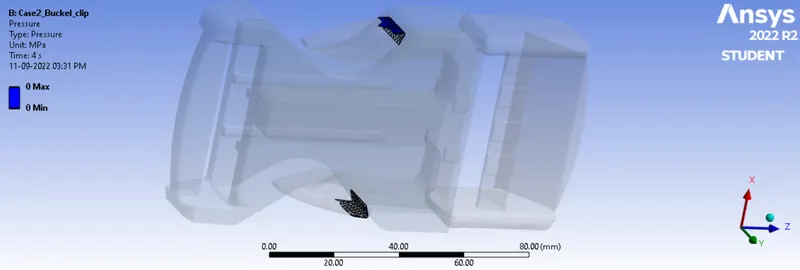
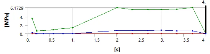
Maximum Contact Pressure over the entire time = 6.1729 MPa - Total deformation of the clip
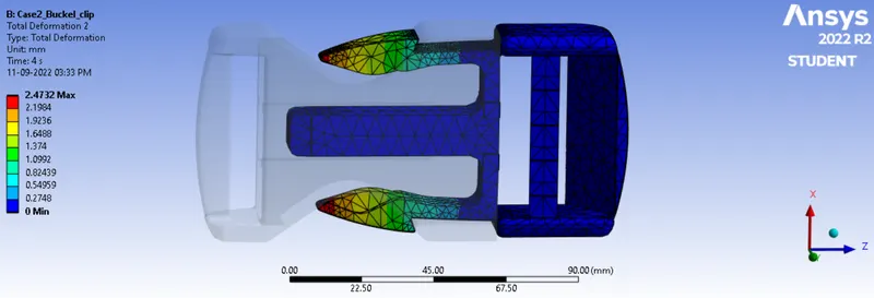
A maximum total deformation of 9.0832 mm is seen along the x direction. - Animations:
- Equivalent Clip Stress:
- Contact Tool: Pressure
- Total Clip Deformation:
- Equivalent Clip Stress:
- Stress generated at the base of the clip
- Comparison of both Cases:
The tabular data gives the comparison for each case:
Case 1 Case 2 Maximum Equivalent Clip Stress 37.767 MPa 36.894 MPa Maximum Contact Pressure 6.0584 MPa 6.1729 MPa Maximum Clip Deformation 9.0174 9.0832
From the table, it is clear that both the cases gives similar results, that is, the results found very closer to each other. This results can be further made to an accurate value by further decreasing the element size.
Conclusion:
The work deals with the investigation of the Buckle Clip simulation using Ansys Workbench. The model was given the appropriate materials, contacts were then applied, and a mesh was developed. Additionally, the boundary conditions were introduced differently for each case and then the simulation was run.
For both the cases, almost same results were obtained, where the maximum equivalent stress acting on the Clip is expected in the range of 37 MPa. The maximum Contact pressure should be expected slighly above 6 MPa and Clip deformation of value slightly greater than 9 mm.