ANSYS Project: Sheet metal Bending
Aim:
To perform a static structural analysis of the bending of sheet metal and analyse different cases.
- Comparison of Equivalent stress, Equivalent elastic strain, and Total Deformation in the Y direction for the sheet with the materials Aluminium Alloy 1199, Copper Alloy NL, and Magnesium Alloy NL.
- Comparison of results for the Aluminium Alloy metal sheet with coefficient of friction of 0.1 and 0.19.
- Comparison of the results for different mesh size for the Aluminium Alloy sheet.
Theory:
The bending of sheets and plates is frequently used to create pieces with corrugations, flanges, and other features. When sheet metal is bent, it is formed into a curved shape by applying bending stress to a flat, straight sheet of metal. The sheet does not alter in thickness but instead deforms plastically. For bending, die and punch are employed. V-bending is the term for the bending process that involves a v-shaped die and punch. Edge bending is the process of bending a sheet of material along its edge using a wiping die. In this procedure, the sheet is bent by a punch that slides vertically down while being held at one end like a cantilever by a pressure pad. Edge bending is often done to create a 90° angle. Tensile stress is applied to the material away from the neutral axis during strip bending. Compressive stress is placed on the inside material. The radius of curvature of the bent sheet inside the bending is known as the bend radius, or R. For elastic bending, the neutral axis stays in the middle of the sheet's thickness. However, when bending plastic, the neutral axis moves toward the inside of the bend. The pace at which outer fibers elongate exceeds the rate at which interior fibers contract Consequently, there is a drop in thickness at the bent section.
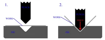
Figure: Sheet Metal Bending using a V Die [reference]
We ignore the thickness loss while bending plastic. The neutral axis is therefore assumed to stay in the center of the sheet thickness. Take into consideration a sheet of thickness `t` that has been bent with a radius of curvature of `R`. We can disregard strain in the direction of breadth. Let the bent angle be `alpha`. The arc length of the neutral axis in the bend area is known as the bend allowance. It is a crucial design factor. It comes from:
`L_b=1/((2R/t)+1`
The outside fibers really bend more than the interior fibers, which contract. As the radius of bending or `R//t` decreases, the strain differential between the outer and inner fibers grows. The tensile strain on the outside fiber may increase over a specific minimum `R//t` to the point where the material outside begins to split. A minimum bend radius is the specific radius at which the outer surface of the bent sheet begins to break. The common unit of measurement is the sheet thickness, abbreviated `t`.
Objectives:
- Getting ready with the Sheet Metal Bending 3D models developed in Solidworks and importing it into the Ansys Workbench for static structural Analysis.
- Apply Boundary Conditions by setting up the contacts and joints. Also editing the analysis setting for the simulation to take place step by step.
- Determine Total Deformation, Equivalent Stress and Directional Deformation results for the performed simulation.
- Conducting the parametric study for the different sheet material cases.
- Conducting a parametric study for different friction coefficient.
- Study of effect of mesh size.
Analysis Setup:
A static structural analysis is to be conducted for the sheet metal bending for three different sheet materials. The material of Punch and Die is set to be structutal steel for the whole analysis.
- Geometry
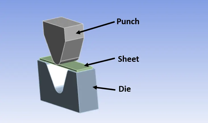
The 3D assembly model of the sheet bending mechanism developed in SOLIDWORKS is shown in figure below: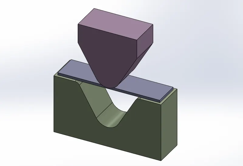
These models are then imported to Ansys Mechanical Static Structural Workbench for the analysis. - Material Properties
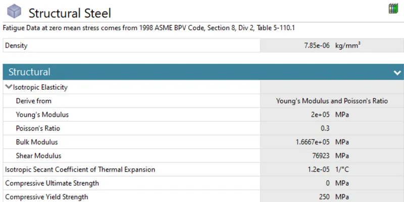
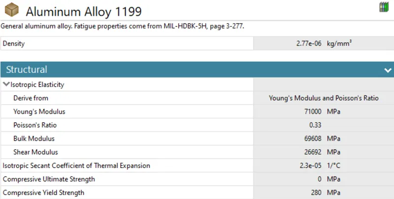
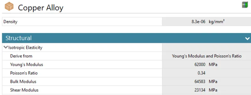
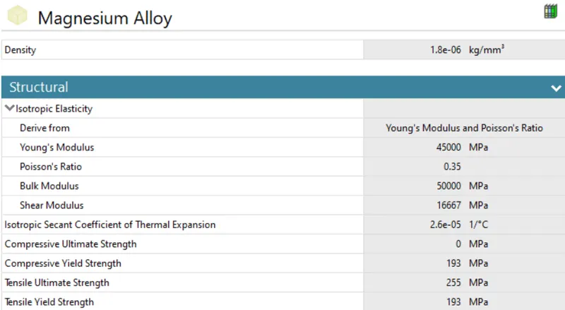
The material of Punch and Die is set to be structural steel for all the analysis. For the first case, analysis is done for the sheet with materials Aluminum Alloy, Magnesium Alloy and Copper Alloy. The material properties are given below:
- Structural Steel
- Aluminum Alloy 1199
- Copper Alloy
- Magnesium Alloy
- Structural Steel
- Contact Details
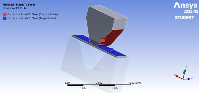
Contact was assigned between two points, namely (a) Punch and the Sheet and (b) the Sheet and the Die. The coefficient of friction for the contact between each contact is given as 0.1. The Behaviour is changed to Auto Asymmetric and the Formulation type used is Augmented Lagrange. The interface treatment is set to Add offset, Ramped Effects.
- Between Punch and Sheet
- Between Sheet and Die
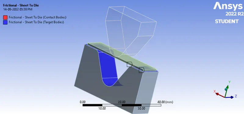
- Between Punch and Sheet
- Meshing
Mesh the model with different mesh options. Using body size option punch and die is mesh in element size of 4 mm. Similarly for sheet the body sizing option is used and mesh in element size of 1 mm and patch conforming method is used for Tetrahedrons meshing.
Using the face sizing option faces of punch and die meshed with 1mm of element size. The total number of nodes and elements generated are 17859 and 6229 respectively. The generated mesh can be seen below: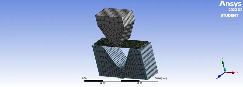

A mesh metric was used to identify elements based on their quality, and it can be observed that the elements of the lowest quality are minimum. The majority of the elements have very high quality values ranging from 0.12021 to 0.99719 with an average value of 0.7092. As a result, the mesh is of reasonable quality. - Boundary Conditions
The total number of steps for analysis is specified as 10. For all steps auto time stepping is program controlled. For all the steps, under solver control, the large deflection is set to ‘On’ and solver type is selected as ‘Direct’. Under non-linear control, the Stabilization is set as 'Constant' and Ratio as 0.1.
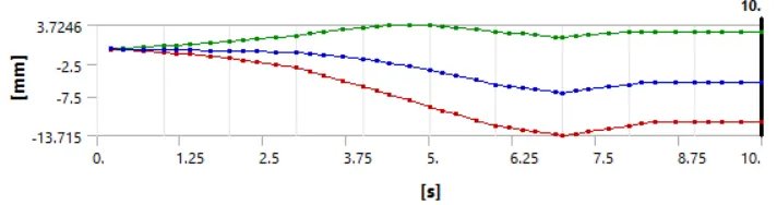
The punch has to move exactly the downward direction, where during the motion, it contact the sheet metal plate. This displacement motion is set up using the table data as shown below: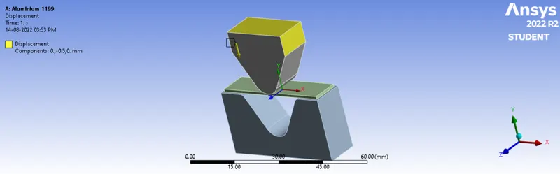
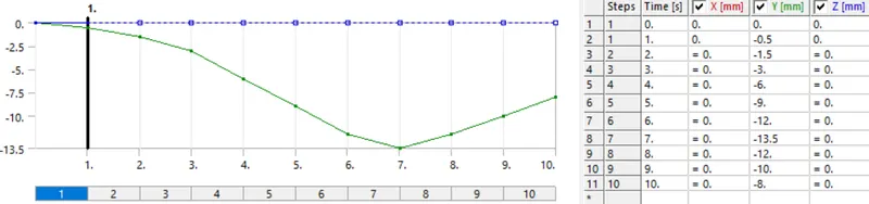
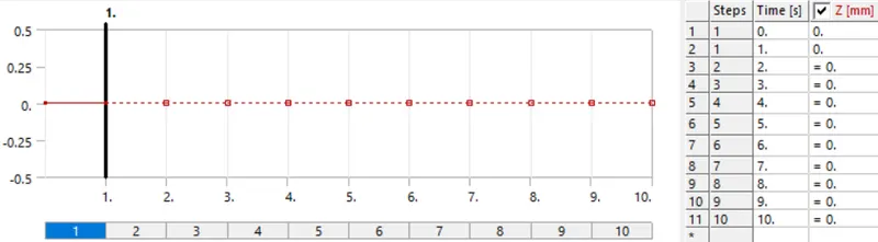
In order to prevent the motion of sheet sideways, the dispacement values of the two sides are set to be zero as shown below: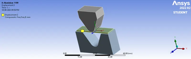
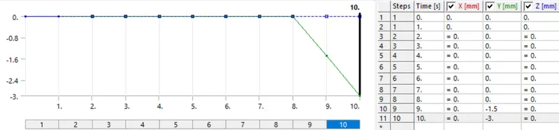
After the Punch presses the metal sheet, the die is also moves away from the sheet similar to the punch. For that, additional dispacement is provided to the Die at the two end substeps as shown below: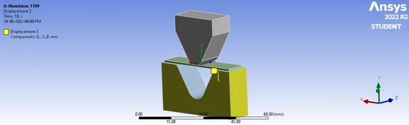
Results:
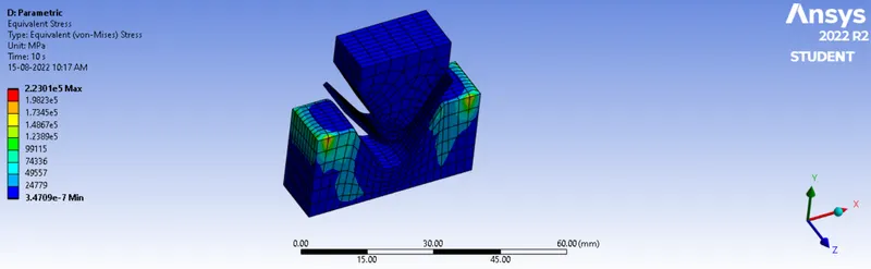
- Case 1: Aluminum Alloy 1199, Copper Alloy NL, and Magnesium Alloy NL are used for the sheet metal. The Equivalent stress, Equivalent elastic strain, and Total Deformation in the Y direction are compared for the three materials.
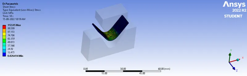
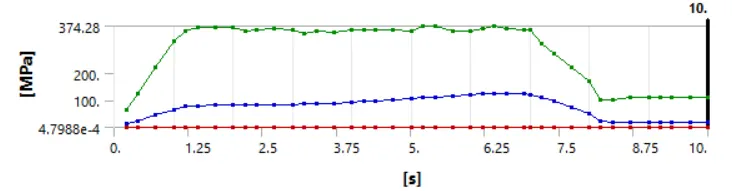
A parametric study was conducted for different material sheets, namely Aluminum Alloy, Copper Alloy and Manesium Alloy. The outputs obtained for each material is provided below:- Equivalent Stress
- Equivalent Elastic Strain
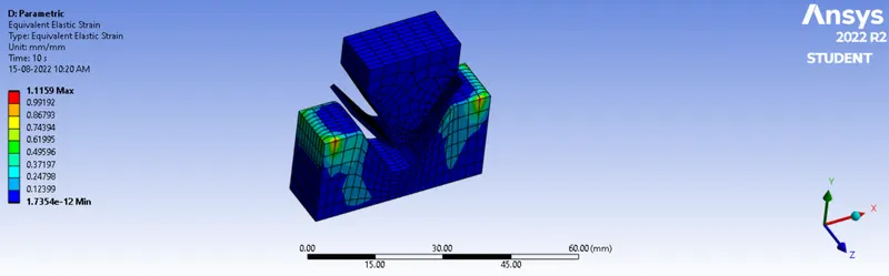
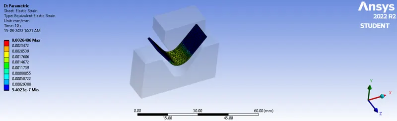
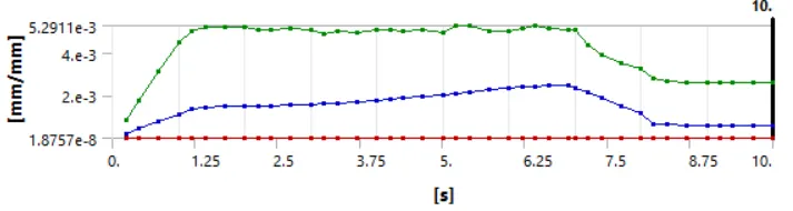
- Directional Deformation
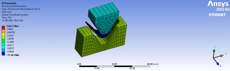
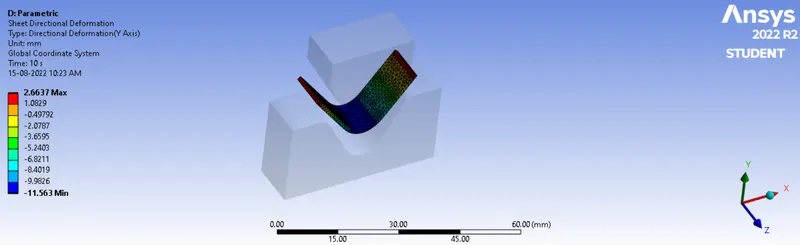
- The output of the parametric study where the maximum value of Equivalent Stress, Equivalent Elastic Strain and Directional Deformation if the sheet alone is shown below:

From the results, the maximum stress results is quite appreciable. It is a section of results for the maximum stresses developed in the sheet metal. When the aluminum alloy NLwas used the induced stress was only 112.05 MPa, but in the case of copper alloy and magnesium alloy it was 4840.7 MPa, and 1992.1 MPa respectively. It shows the formability of the aluminum material.
- Animations
- Sheet Equivalent Stress:
- Sheet Equivalent Elastic Strain:
- Sheet Directional Deformation:
- Sheet Equivalent Stress:
- Animations
- Equivalent Stress
- Case 2: With the material as Aluminium Alloy, comparison of results with change of the friction coefficient to 0.19
A parametric study was conducted for Aluminum Alloy sheet for different frictional coefficient values. Since there are two different contact points for the sheet, two different friction coefficient values can be assigned. Since the material of Die and Punch is Structural Steel, which is same, the coefficient of friction between sheet and punch as well as between sheet and Die is changed to a same value (1.19, here). The outputs obtained for each frictional coefficient is provided below:
The Frictional coefficient will have an impact on the punch force needed and therefore it is useful to keep it as low as possible. The more the frictional coefficient, the more will be the stress and strain acting on the sheet which will in turn affect the sheet during the sheet bending process. - Case 3: Refine the mesh on the plate with Aluminium alloy as material and comparison of the result with old mesh size.
A parametric study was conducted for Aluminum Alloy sheet for different sheet element sizes of sheet plate. The patch conforming method is used for Tetrahedrons meshing. The element size of 1 mm and 0.6 mm are studied. The outputs obtained for each element size is provided below: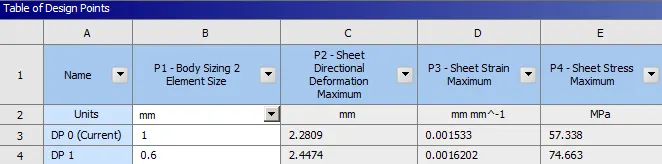
It can be observed that there is a significant change in the stresses induced in the sheet metal. In the case of mesh with a 1 mm element size, the maximum stress induced was 57.338 MPa, and in the case of mesh with element size 0.6 mm, the maximum stress induced was 74.663 MPa. It means in earlier cases there was a difference of 79% of the maximum stress from yield strength, and now it is 73%. Thus, after the removal of the load from the sheet, the high stresses remain closer to the yield point. Therefore, the element size of 0.6 mm is preferred over the 1 mm element size.
Conclusion:
The sheet metal had to bend for this project, and any stresses or strains that resulted from that bending had to be examined. Three distinct goals were used to complete the task. For the first goal, three different sheet metal materials' stresses and other factors were examined. Out of aluminum alloy 1199, copper alloy, and magnesium alloy, it was discovered that aluminum alloy 1199 should be the favored material. Aluminum alloy is easily formed. The coefficient of friction between contact surfaces was raised from 0.1 to 0.19 for the second aim. However, it had little impact on the outcome. The restricted mobility of sheet metal may be the cause. The sheet metal's mesh was reduced in size in the third objective from 1 mm to 0.6 mm, and its equivalent stress was increased from 57.338 MPa to 74.663 MPa. This demonstrates the impact of mesh density on the outcomes.