SOLIDWORKS Project: American Chopper [Design and Photo Realistic Render]
Design and Photo Realsitic Rendering of American Chopper using SOLIDWORKS
Aim:
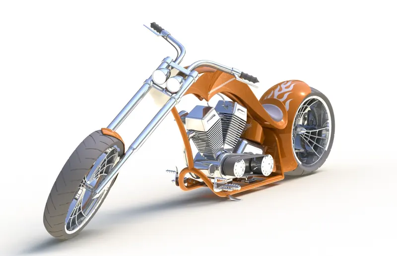
To design an American Chopper in SOLIDWORKS and to do a photo realistic rendering.
Introduction:
Choppers are a sort of custom motorbike that first appeared in California in the late 1950s. The chopper is the most severe of all custom models, with significantly altered steering angles and longer forks for a stretched-out look. They can be created from a modified original motorbike or from scratch. Long front ends with extended forks, often coupled with an increased rake angle, hardtail frames (frames without rear suspension), very tall "ape hanger" or very short "drag" handlebars, lengthened or stretched frames, and larger than stock front wheels are some of the distinguishing features of choppers.
Objectives:
- To create the model of individual parts of chopper in part modeling environment using SOLIDWORKS.
- To assemble created models of invidual parts of Chopper in the assembly environment.
- To create a photo realistic model of the chopper and render it in SOLIDWORKS Photoview 360 and SOLIDWORKS Visualize.
Part Modeling:
In general, modeling entails creating a virtual prototype of an object. It may be used for a variety of things. Consider a car's engine, which includes hundreds of components. Each component may be modelled independently and then integrated to generate the engine's final shape. Part Modelling is the name given to this form of modeling.
Assembly:
An assembly is a grouping of individual model pieces that are combined in an assembly environment to form a bigger, more complicated product representation.
- Assembly Modeling Approaches
- Bottom-Up Assembly Approach
Individual parts are made separately, integrated into the assembly, and positioned and orientated (using mating conditions) as specified by the design. If the pieces have already been built, the bottom-up method is the preferable option (off the shelf). It enables the designer to concentrate on the individual components. It also makes it easier to preserve the top-down approach's connection and regeneration behavior of the pieces. - Top-Down Asembly Approach
The assembly file is prepared initially using an assembly layout sketch in this method. The components are created in the assembly file, or the concept drawings for the parts are entered and finished there. In other words, the final geometry of the pieces was not determined before they were included to the assembly file. The method is perfect for huge assemblies. - The Middle Out Approach
The bottom-up and top-down assembly modeling methodologies are combined in the middle-out assembly modeling methodology. This sort of assembly model is often built with the majority of the parts already produced and new parts planned and created utilizing the assembly for building information.
- Bottom-Up Assembly Approach
Design and Modeling:
Except for the Gas Tank, which was designed using Surface modeling, the Chopper was designed primarily using Solid modeling.
- Tools and Features Used
- Extrude Boss: Extrude Boss is a feature that allows us to transform 2D designs to 3D by adding thickness in the third dimension.
- Revolved Boss: It is used to generate a solid 3D model centered on an axis. You may add materials to the drawing by rotating it around an axis.
- Sweep Boss/Cut: By sweeping a totally closed profile down a route, it is possible to add or remove material from a solid model or part. Swept Boss or Base-up adds solid material to the design's body, whereas Swept Cut removes material from the design's body.
- Fillet: Fillets are used to round off the edges and/or corners of objects. Fillet adds or subtracts material depending on whether the edge is internal or exterior in order to round edges or corners. There are manual fillet and fillet expert options available, depending on the intricacy of the model or the number of models to fillet.
- Shell: The shell tool hollows down a component, leaving the selected faces exposed, and creating thin-walled features on the remaining faces.
- Loft Boss / Loft Cut: A loft is made up of two or more profiles. Points can only be assigned to the first, last, or first and last profiles.
- Linear Pattern/Circular Pattern/Curve Driven Pattern: It is used to generate numerous instances of one or more characteristics that can be evenly spaced along one or two linear or circular pathways. In a linear pattern, we must choose the linear path pattern that must be followed. In a circular design, we must choose which circular direction the pattern should take. We have chosen the curve along which the pattern must be followed in a curve-driven pattern.
- Mirror: It enables us to reproduce features in the same way that the mirror image does. We can reflect features along a plane, an axis, a face, reference geometries, and so on. We can also reflect patterns, bodies, and multi bodies, which makes creating more easier.
- Projected Curve: This tool is highly handy for creating complicated 3D curves. Using this tool, drawing curves in multiple planes with certain common points and merging them helps to produce smooth 3D curves.
- Split: The split tool operates in the same way as the extruded cut tool, but it provides a lot more possibilities for cutting out portions. It is useful for cutting off intersecting portions and removing unneeded interior or external pieces.
- Reference Geometry: The shape or form of a surface or solid is defined by reference geometry. Planes, axes, coordinate systems, and points are examples of reference geometry.
- Mates: Mates establish geometric links between the many elements we created. It aids in the creation of various mates with concentric, parallel, perpendicular, tangent, and other relationships.
- Description of Parts and Features Used
- Transmission Belt
Transmission Belt is a loop of flexible material used to link the two rotating shafts mechanically.
Commands used: Sketch, Extruded Boss, Offset Entities, Fillet.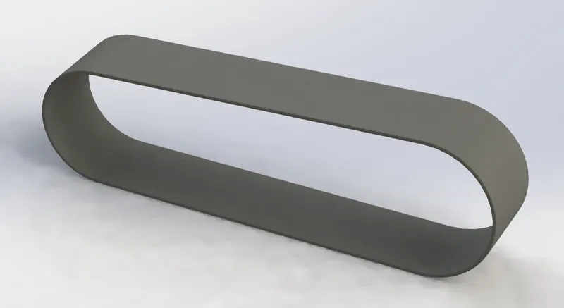
- Kickstand
Kickstand is used to suport the vehicle by keeping it upright.
Commands used: Sketch, Lofted Boss, Dome, Extruded Cut, Split body, Extruded Boss, Fillet.
Some design changes were made to the kickstand during the assembly for getting the desired render results.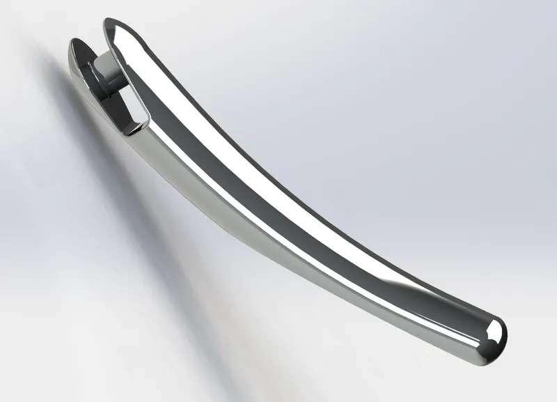
- Front Fender
Fender is body that frames the wheel well. Its primary purpose is to prevent sand, mud, rocks, liquids, and other road spray from being thrown into the air by the rotating tyre.
Commands used: Sketch, Offset Entities, Revolved Boss, Split Body, Fillet.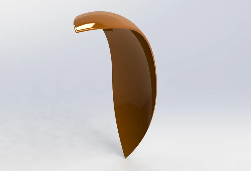
- Rear Fender
Fender is body that frames the wheel well. Its primary purpose is to prevent sand, mud, rocks, liquids, and other road spray from being thrown into the air by the rotating tyre.
Commands used: Sketch, Offset Entities, Revolved Boss, Split Body, Fillet.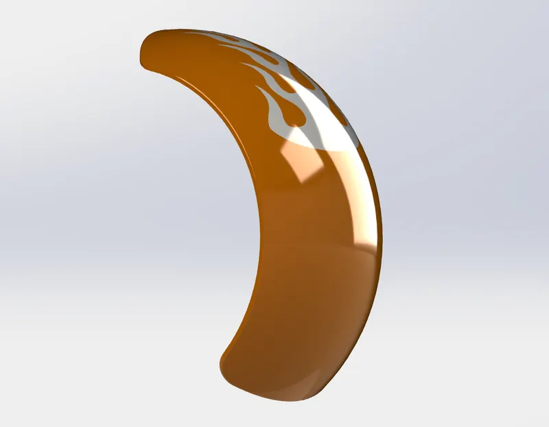
- Oil Tank
Stores the oil for lubrication and cooling purposes.
Commands used: Sketch, Extruded Boss, Combine, Fillet, Shell.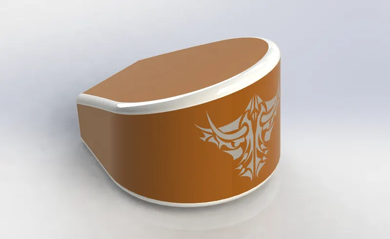
- Chain
Chain drive is used for transmission of mechanical power, in this case the power from the engine to the wheels of the vehicle.
Chain drive design was a lengthy process as it required repetition of the various commands. But the curve driven pattern and mirror commands in SOLIDWORKS came in handy for this case.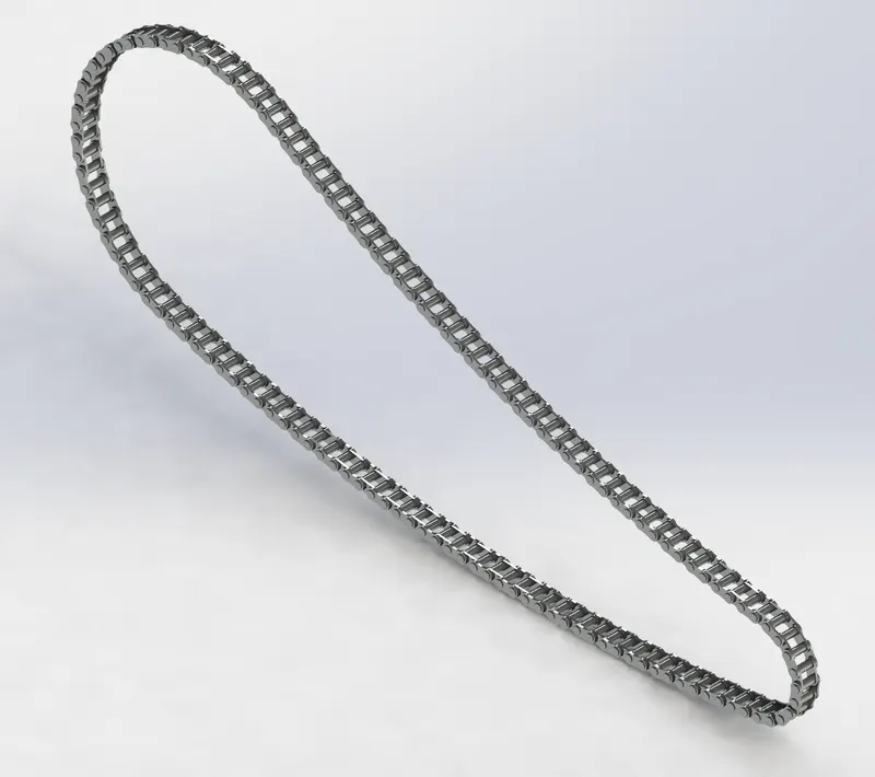
- Pedal
It is used for placing the foot, applying brakes and shifting the gear in a motorcycle.
Commands used: Sketch, Extruded Boss, Fillet, Revolved Boss, Dome, Chamfer, Linear Pattern.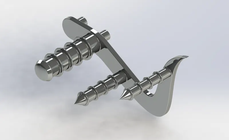
- Front Wheel
The front wheel consists of the unique spider web shaped rims, type, brake rotor and caliper.
Commands used: Sketch, Offset Entities, Convert Entities, Trim ENtities, Revolved Boss, Extruded Boss, Extruded Cut, Revolved Cut, Circular Pattern, Combine, Fillet, Chamfer.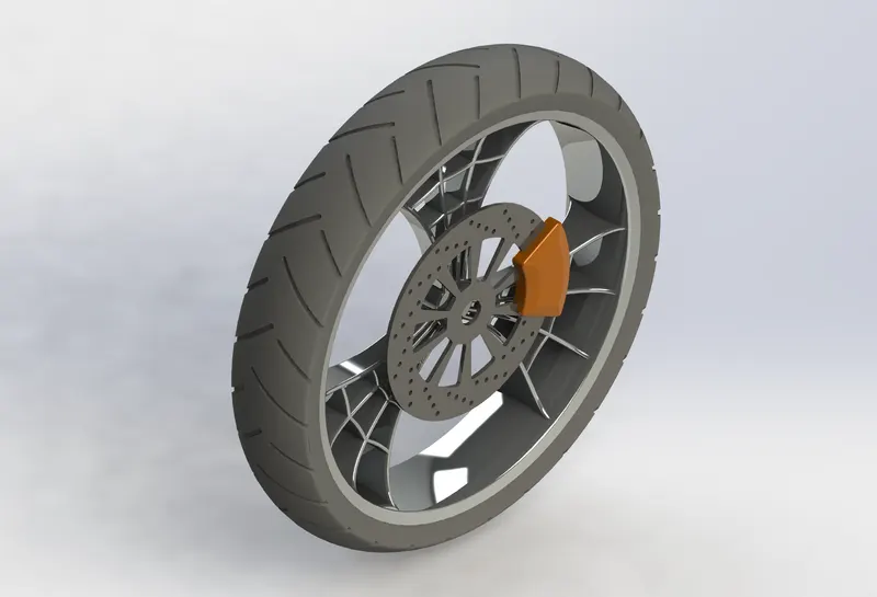
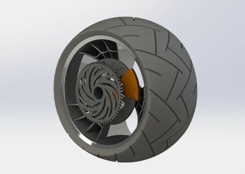
- Rear Wheel
The wider but stockier rear wheel consists of the unique spider web shaped rims, tyre, brake, brake rotor, caliper and sprocket.
Commands used: Sketch, Offset Entities, Convert Entities, Trim Entities, Revolved Boss, Extruded Boss, Extruded Cut, Revolved Cut, Circular Pattern, Combine, Fillet, Chamfer.
- Front Fork
The front fork connects the front axle and axle to its frame, typically via a yoke, also known as triple clamp, which consists of an upper yokr joined to a lower yoke via a steering stem, a shaft that runs through the steering head, creating the steering axis.
Commands used: SKetch, Revolved Boss, Extruded Boss, Fillet, Linear Pattern, Extruded Cut, Dome, Revolved Cut, Move/Copy Body, Project Curve, Swept Body, Swept Boss, Mirror, Combine.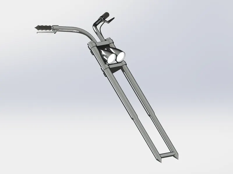
- Chassis
Chassis/Frame is the motorcycle's core structure. It supports the engine, provides a location for the steering and supports the rear end and the rider along with any passenger or luggage. The fuel tank is attached to the frame.
Commands used: Sketch, Convert Entities, Project Curve, Swept Boss, Mirror, Extruded Boss, Extruded Cut, Chamfer, Fillet, Dome, Split Body, Combine.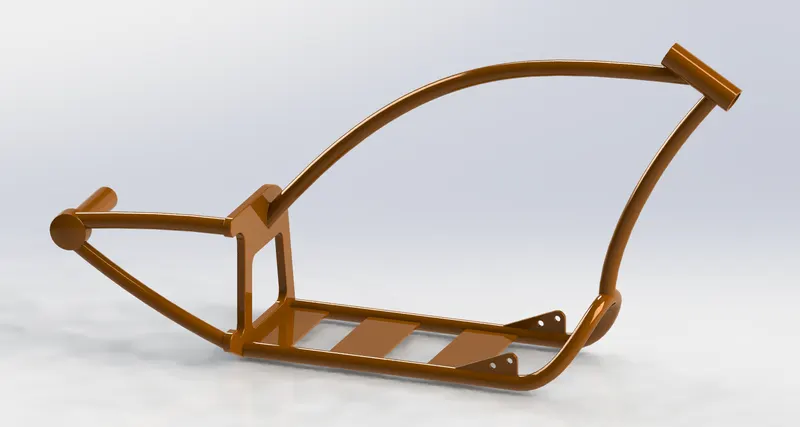
- Engine
An Engine powers a motorcycle. Here, a V-Twin engine, also called a V2 engine is used. It is a two-cyclinder piston engine where the cylinders share a common crankshaft and are arranged in a 'V' configuration. The V configuration generally reduces the overall engine length, height, and weight compared with an equivalent inline configuration.
Commands used: Sketch, Convert Entities, Extruded Boss, Revolved Boss, Fillet, Circular Pattern, Dome, Extruded Cut, Chamfer, Linear Pattern, Mirror, Split Body, Swept Boss, Combine, ProjectCurve, Composite Curve.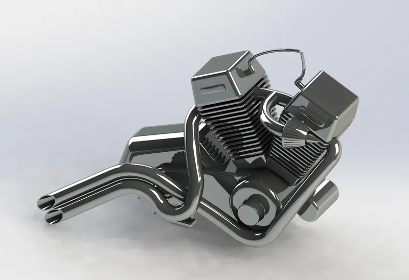
- Gas Tank
Unlike other parts where Solidmodelling was used, gas tank was majorly designed using surface modelling, given its curvy geometry.
Commands used: Sketch, Convert Entities, Swept Surface, Trim Surface, Project Curve, Lofted Surface, Boundary Surface, Mirror, Knit Surface, Spline Line, Extruded Surface, FIllet, Swept Cut, Shell.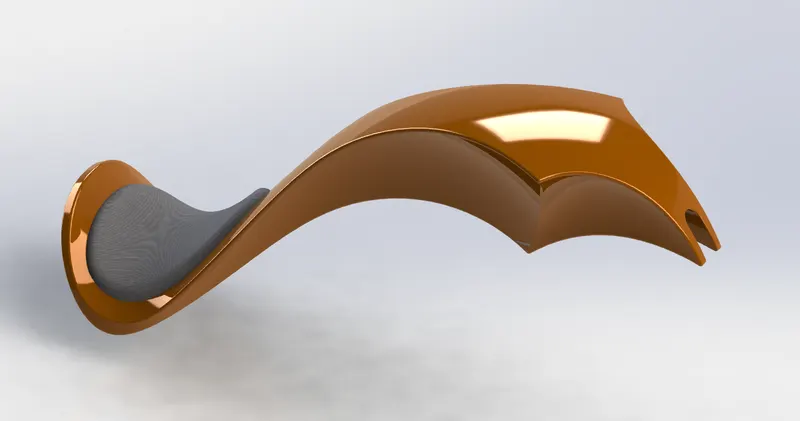
- Transmission Belt
- Assembly
All the modelled parts were inserted one by one in the assembly. The parts were inserted randomly in the assembly environment and were given maual mates by taking chassis as the reference sii that all the parts move with respect to the chassis only when the chassis floats.
Mates build geometric relations between components of the assembly. The permissible paths of linear or rotational motion of the components can be defined as the matches are added. Inside their level of independence, a part may be transfered, visualizing the assembly's behaviour.
Types of Mates
Standard Mates: Angles, Coincident, Concentric, Distance, Lock, Parallel, Perpendicular, Tangent Mates.
Advanced Mates: Limit, Linear/Linear Coupler, Path, Symmetry, Width Mates.
Mechanical Mates: Cam-Follower, Gear, Hinge, Rack and Pinion, Screw, and Universal Joint Mates
- Front View
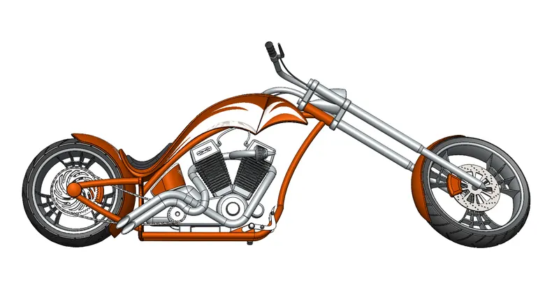
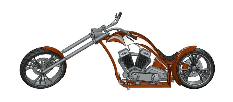
- Side View
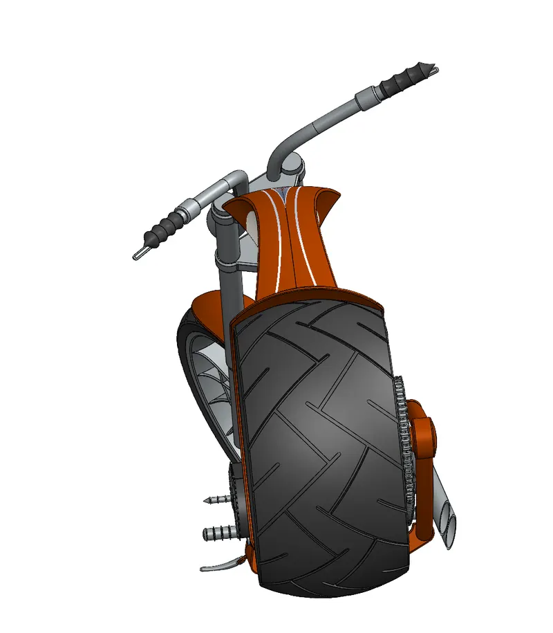
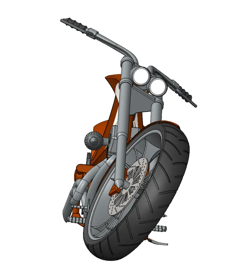
- Isometric View
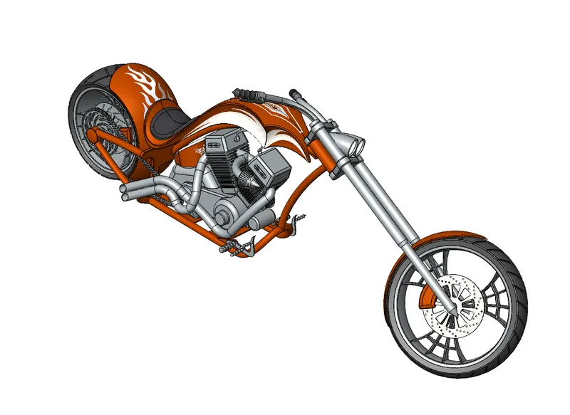
- Camera Setup View
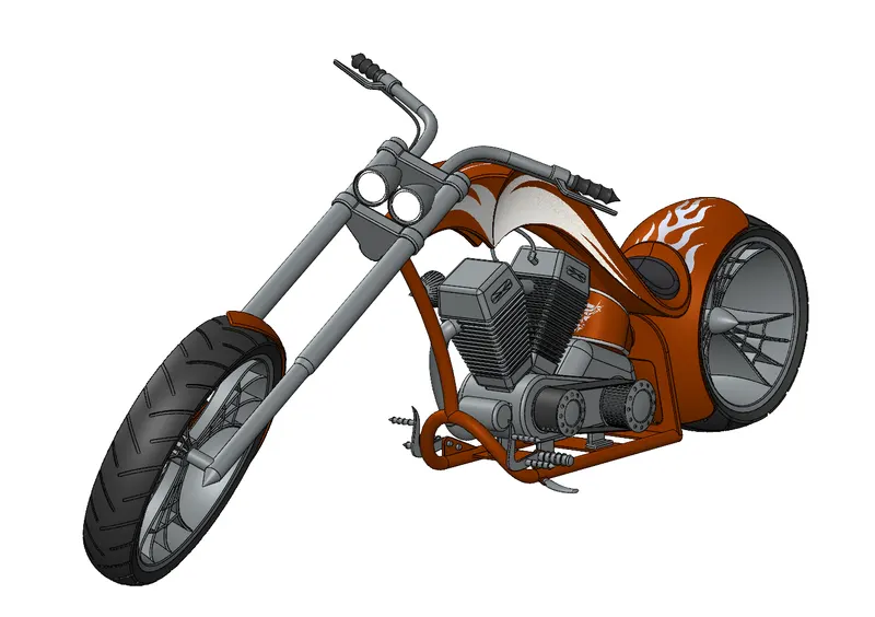
- Top View
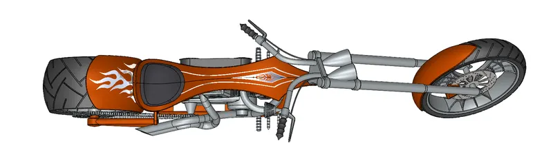
- Front View
- Rendering
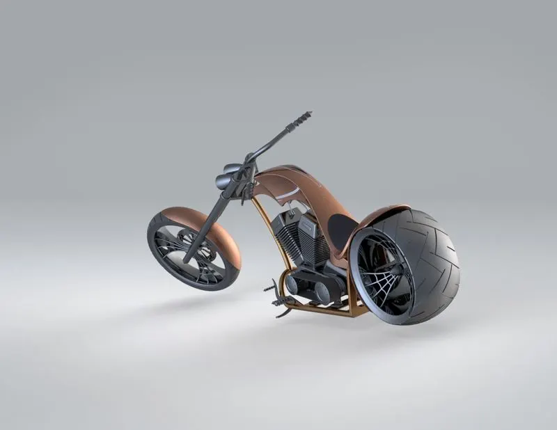
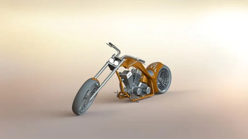
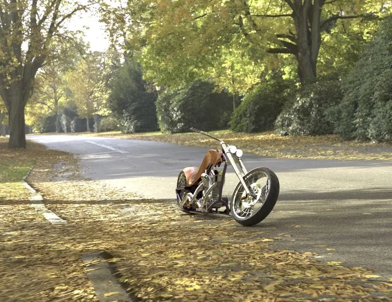
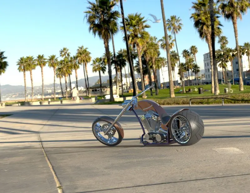
Rendering is the process of creating realistic images with the photo realsitic environment. Rendering has been done in two ways in SOLIDWORKS:
1. Photoview 360
2. SOLIDWORKS Visualize
In the photo realistic model, some of the mate conditions and positions were changed to render realsitic models. Then the photorealistic model is rendered into realsitic images with different views.
- Rendering Done in Photoview 360
- Rendering Done in SOLIDWORKS VISUALIZE
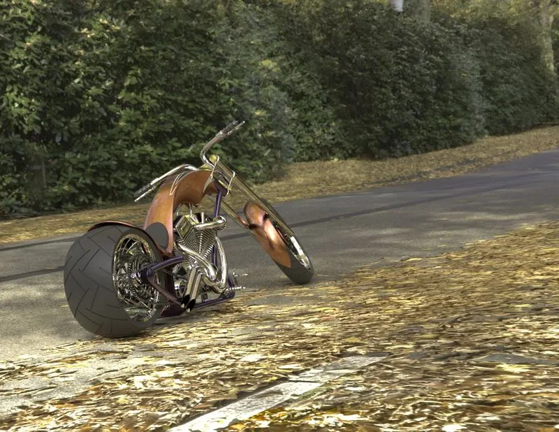
- Rendering Done in Photoview 360
Conclusion:
All the parts of the Amercan Chopper were modelled and the assembly was created using SOLIDWORKS. The photo realistic renders of the chopper was then created on SOLIDWORKS Visualize.