Simulink Project: Controlling Fan using Thermistor
Aim:
To make a Simulink model where a thermistor sense the temperature of a heater and turn on or turn off the fan as per requirement.
Theory:
Thermistors are temperature-dependent resistors whose resistance changes as the temperature rises. They are extremely sensitive and react to even the tiniest changes in temperature [1]. They're best for maintaining a specific temperature and monitoring temperatures within 50 degrees Celsius of ambient. The best technique to measure and control the heating and cooling of a Peltier device is to use a Thermistor as part of a temperature control system. Because of their capacity to alter in minute increments, they have the most overall system capability. Thermistors can be embedded in a surface, installed on a device that has to be monitored for temperature. They can measure both fluids and solids, depending on the kind. Metallic oxides make up their composition.
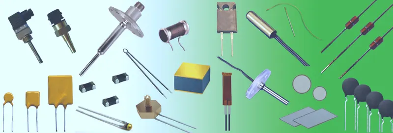
Figure 1: Thermistor Types [2]
NTC and PTC Thermistors are the two basic types of thermometers. Resistance decreases when temperature rises in NTC thermistors, owing to an increase of conduction electrons bumped up by thermal agitation from the valency band. An NTC is typically employed as a temperature sensor or as an inrush current limiter in series with a circuit. Resistance increases as temperature rises in PTC thermistors, owing to increasing thermal lattice agitations, particularly those caused by impurities and defects. PTC Thermistors are often employed as resettable fuses in series with a circuit to protect against overcurrent circumstances.
Objectives:
- Understanding the theory of Thermistors: working principle and applications.
- Creating a Simulink model where a thermistor senses the temperature of a heater, and turn on or turn off the fan as per requirement.
- Evaluation of the model.
Simulink Model:
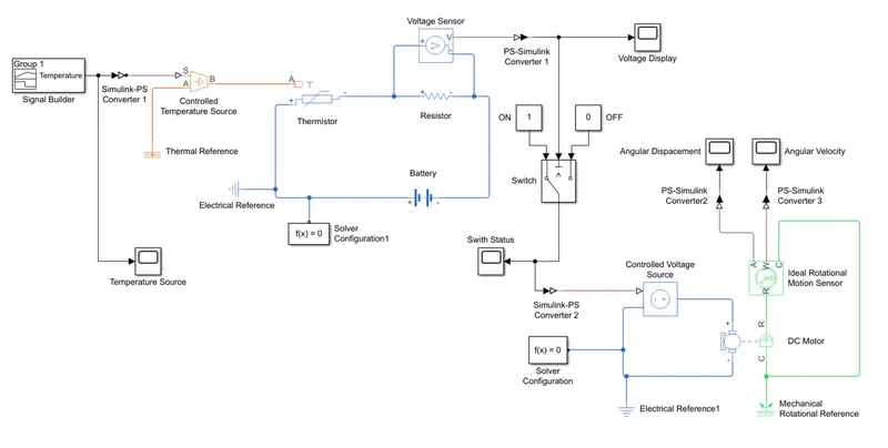
Explanation of the Block set
Signal builder is used to build input temperature signal as required. This build temperature signal can be viewed through the scope Temperature Source. This temperature signal is converted into physical form using Simulink-PS Converter 1. The Controlled Temperature Source represents an ideal energy source in thermal network that can maintain a controlled temperature difference regardless of the heat flow rate [3]. The temperature difference is set by the physical signal port S. The temperature at port B will be greater than the temperature at port A, if the temperature difference is positive. Thermal Reference is ground the thermal network. The Thermistor block represent the NTC thermistor using the B-parameter equation [4]. The resistance at a temperature is given by `R(T) = R_0*e^(B*(1/T-1/(T_0))`, where `R_0` is the nominal resistance at the reference temperature `T_0` and
`B` is the characteristic temperature constant. The temperature difference on the thermistor varies the resistance of the electrical circuit. Resistor is used to set up Voltage Sensor to find the potential difference in caused due to change in resistance of electrical circuit due to temperature difference. Battery is the power source and Solver Configuration 1 defines the setting to use for simulation for the electrical network. Electrical Reference provides grounding for the electrical network. PS-Simulink Converter 1 converts the physical signal into the simulink form that can be displayed in scope Voltage Display. This signal is also transformed Switch, which control the condition based on the threshold value. The status of the switch which tells if the switch is on can be displayed with scope Switch Status. This signal to be used for the electrical side of DC Motor is converted into physical form using Simulink-PS Converter 2. The electrical side of DC Motor consists of Controlled Voltage Source, Electrical Reference 1, and Solver Configuration. The Controlled Voltage Source is to regulate the voltage when the threshold condition of switch is satisfied. Electrical Reference 1 for grounding the electrical network and Solver Configuration to define solver settings to use for simulation for the electrical side of DC Motor. The mechanical rotation of the DC Motor is sensed by Ideal Rotational Motion Sensor. It senses the angular velocity and angular displacement which can be viewed through scopes Angular Displacement and Angular Velocity, after the physical signal is converted from physical form to simulink by PS-Simulink Converter 2 and PS-Simulink Converter 3. The Mechanical Rotational Sensor is used to provide reference for mechanical parts.
Output and Explanation of the Block set:
The input required for the complete block set is defined using the Signal Builder. It is defined for 50 seconds as shown below:
- 0 - 10 sec: 20`"degree Celsius"`
- 10 - 30 sec: 27 `"degree Celsius"`
- 30 - 50 sec: 23 `"degree Celsius"`
The built signal can be seen through scope Temperature Source as shown in Figure 2.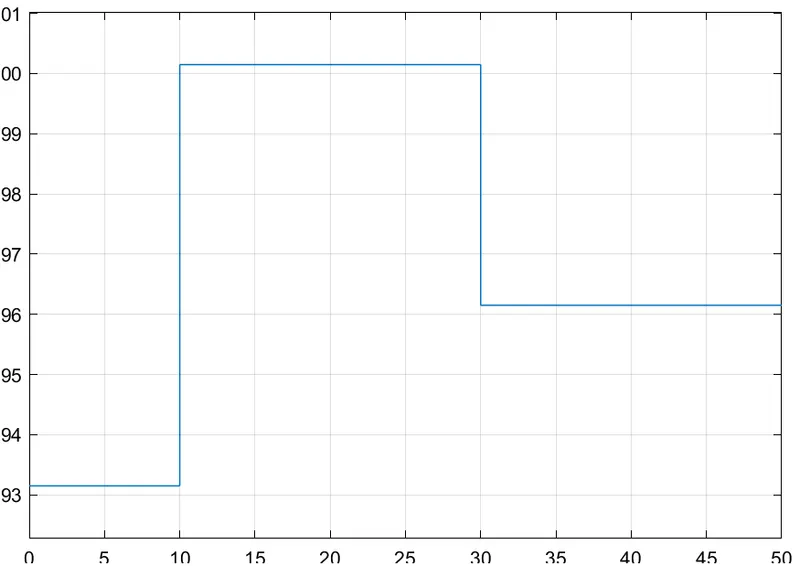
Figure 2: Temperature source (Temperature with time)
The built signal before fed into the Controlled Temperature source the setting of the "Physical Signal Convertor" is needed to be modified. In the input handling, the filter input & derivative has to be selected instead of signals. This is because as we use two heat sources in the Controlled Temperature Source. The thermal reference can provide ideal energy in a thermal network that can maintain a controlled temperature difference regardless of the heat flow rate.
This temperature variation responsible to change in the resistance of the electrical circuit due to Thermistor, leading to the change in voltage across resistor which can be seen in Voltage Display as shown in Figure 3.
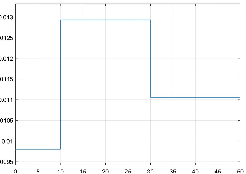
Figure 3: Votage variation in Electrical Circuit due to Thermistor.
The motor of Fan needs to be on if the temperature is greater than 25 degrees Celsius, which means that there is a voltage value corresponding to the 25 degrees Celsius which need to be set as the threshold value for the switch. If only the voltage is greater than the threshold value, the switch is ON. The voltage value corresponding to 25 degrees Celsius was found to be 0.0119642 V and it was imputed to the switch. The status of the switch (whether it is ON or OFF) according to the input temperature source can be seen through the scope Switch Status as shown in Figure 4. It is seen that the switch is ON in the time interval 10 to 30 seconds, where the input temperature is greater than 25 degrees Celsius, this would in turn switch in motor in this interval.
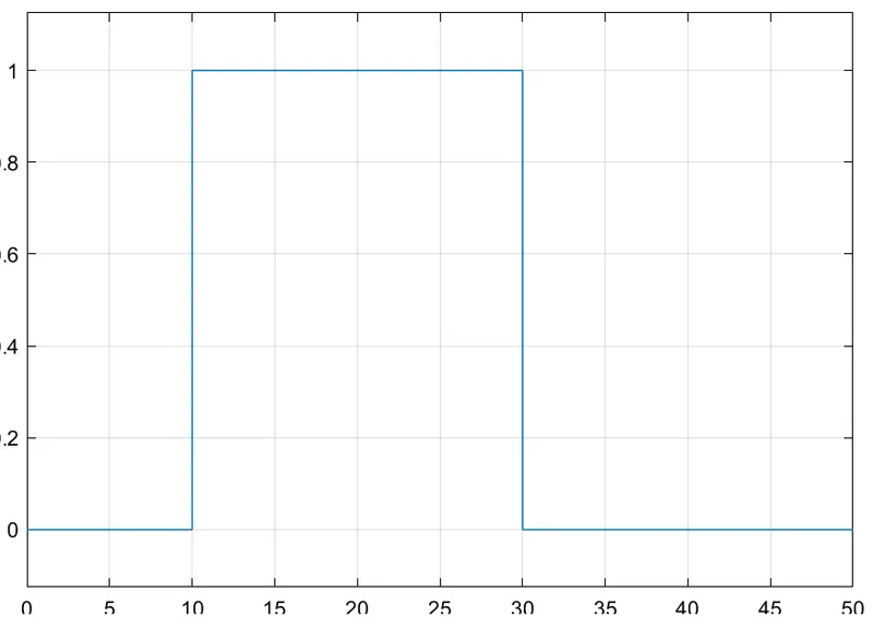
Figure 4: Status of the Switch according to the temperature input.
If the switch is ON position, the motor starts working leading to the change of angular position and angular velocity of the rotor. This change according to the temperature input can be seen through scopes Angular Display and Angular Velocity as shown in Figure 5 and 6. It is seen that the angular velocity and position changes only at the interval 10 to 30 seconds as the temperature input in this interval is greater than 25 degrees Celsius.
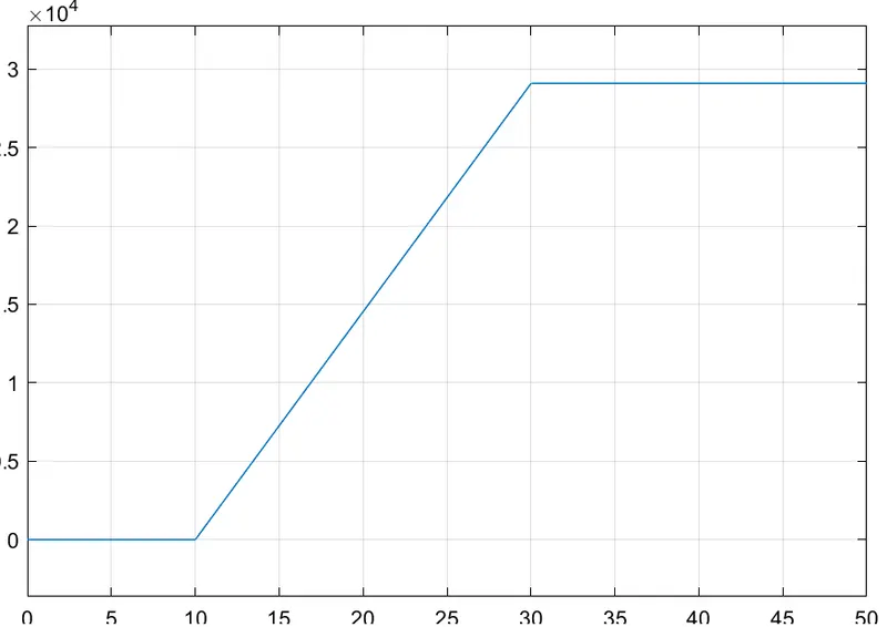
Figure 5: Angular position of DC Motor in the complete time interval.
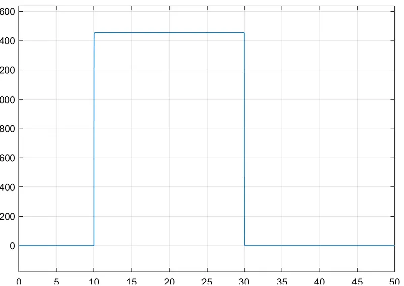
Figure 6: Angular velocity of DC Motor in the complete time interval.
Conclusion:
A Simulink model of Control system to switch ON and OFF the motor using the Thermistor is made successfully and a situation is created where the input temperature for a time interval of 50 seconds made as per required. The functionality of the model created checked successfully if it turns ON the Fan if the temperature is greater than 25 degrees Celsius.
References:
[1] https://www.omega.com/en-us/resources/thermistor
[2] https://www.teamwavelength.com/thermistor-basics/
[3] https://www.mathworks.com/help/physmod/simscape/ref/controlledtemperaturesource.html
[4] https://www.mathworks.com/help/physmod/sps/ref/thermistor.html