ANSYS Project: Rolling operation
Aim:
To perform a static structural analysis of the Rolling Operation for the Copper Material and to evaluate the results.
Theory:
- Rolling
By applying compressive stresses through a set of rolls, rolling is the process of lowering the thickness or altering the cross section of a continuous strip. Shape rolling is another technique used to create items with different cross sections in addition to flat rolling. Plates, sheets, foil, rods, seamless pipes, and tubing are examples of rolling products. Shape-rolled products, such as I-beams and structural shapes, are another. Bars with different cross sections are another. Ring rolling and thread rolling are additional rolling processes.
The process of rolling can be done either at low temperatures (cold rolling) or at high temperatures (hot rolling). Roll diameter (relative to material thickness), reduction per pass, speed, lubrication, and temperature are some of the material and process variables that are involved in the process. Important factors to take into account when managing the rolled stock's dimensional accuracy include spreading, bending, and flattening. - Flat Rolling Process
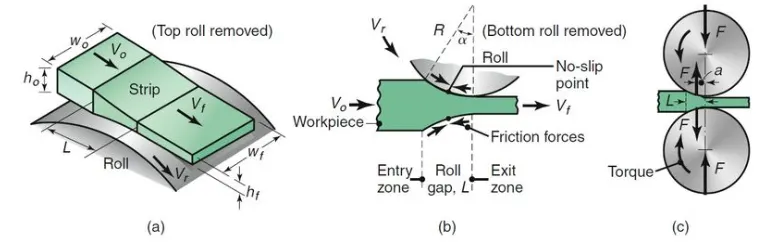
The flat rolling process is schematically represented in Figure (a). When a metal strip of thickness `h_0` enters the roll gap, a pair of spinning rolls that are each driven by an electric motor reduce it to thickness `h_f`. The rolls' surface speed is `V_r`. As the strip goes through the roll gap, its velocity rises from its initial value of `V_0`; this increased velocity is designated as `V_f`, and it reaches its maximum at the exit from the roll gap. In the roll gap, the metal accelerates similarly to an incompressible fluid moving along a converging channel. Because the rigid roll's surface speed is constant, there is relative sliding along the arc of contact in the roll gap, `L`, between the roll and the strip. The velocity of the strip and the roll are equal at a particular location along the contact length known as the neutral point or no-slip point. The roll moves more quickly than the strip to the left of this point, and the strip moves more quickly to the right of this point. As a result, the strip experiences the frictional forces that prevent motion between two sliding bodies as shown in Figure (b).
By exerting a net force of friction on the material, the rolls draw it into the roll gap. As a result, in Figure (b), the net frictional force must be to the right. This implies that the frictional force must be greater to the left of the neutral point than to the right. Although friction is required for rolling materials, overcoming friction requires energy. Thus, when friction grows, so do rolling forces and energy needs. High friction can also wear down the surface of the rolled product. In order to achieve this compromise in practice, effective lubricants are used to roll with low and regulated friction.
The difference between the initial and final strip thicknesses is used to determine the maximum draft that can be made, or (`h_0-h_f`). The following equation can be used to demonstrate how this quantity depends on the roll radius, `R`, and the coefficient of friction between the strip and the roll:
`mu=sqrt((h_0-h_f)/R`
When rolling plates and sheets with large width-to-thickness ratios, the strip's width practically stays constant. With lesser ratios, however, the width of the strip significantly expands as it moves through the rolls (for example, a strip with a square cross section). Spreading refers to this increase in width. It can be demonstrated that spreading rises with lowering roll radius to strip thickness ratios, rising friction, and decreasing the width-to-thickness ratio of the entering strip (due to the removal of the width limitation). The last two consequences result from the roll gap's enhanced longitudinal material flow limitation. Spreading can also be avoided by utilizing edger mills, which are additional rolls (with vertical axes) that come into contact with the edges of the rolled product in the roll gap and impose a physical restriction on spreading.
Objectives:
- Getting ready with the Rolling Operation 3D models developed in Solidworks and importing it into the Ansys Workbench for static structural Analysis.
- Modification of the dimensions of the 3D model for the analysis purposes.
- Apply Boundary Conditions by setting up the contacts and joints. Also editing the analysis setting for the simulation to take place step by step.
- Determination of Equivalent Stress, Equivalent Plastic Strain and Deformations of the setup for the performed simulation.
- Analysing the result.
Analysis Setup:
A static structural analysis is to be conducted for the Rolling Operation setup for the work piece material Copper. The material of both the Rollers are set to be structutal steel for the whole analysis.
- Geometry
The 3D assembly model of the Rolling Operation Setup developed in SOLIDWORKS is shown in figure below:
These models are then imported to Ansys Mechanical Static Structural Workbench. For the proper analysis of this assembly model, certain modifications were done in Spaceclaim such as increasing the length of the workpiece by 60 mm and decreasing its size on both sides by 8 mm. The updated 3D model done in Spaceclaim is shown below: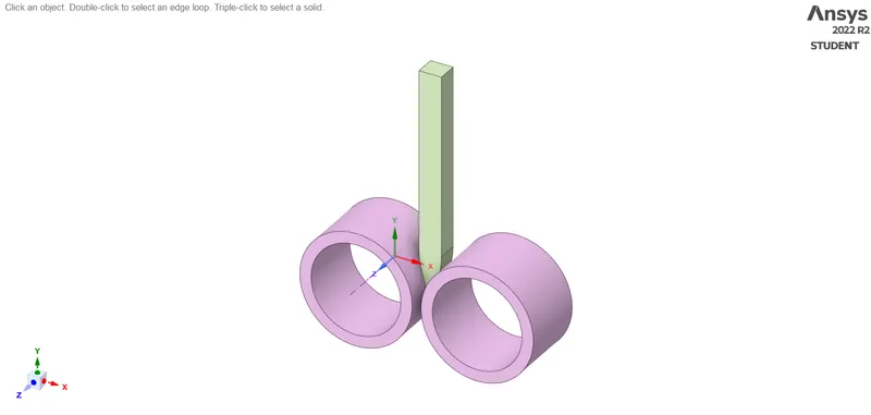
- Material Properties
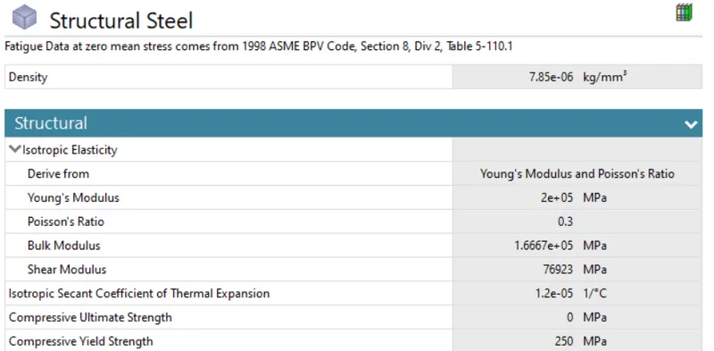
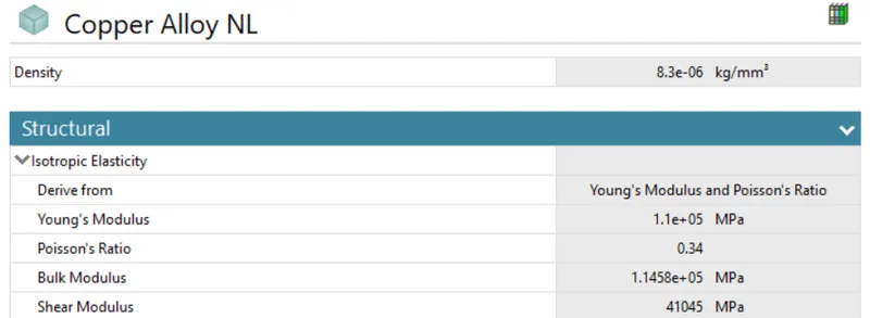
The material of both rollers are set to be structural steel for all the analysis. The material of workpiece is set be Copper for the whole analysis. The material properties are given below:
- Structural Steel:
- Copper Alloy:
- Structural Steel:
- Contact Details
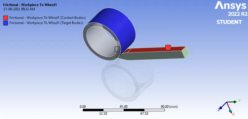
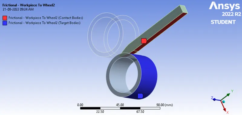
Contact between the Workpiece (contact body) and wheel 1 (target body), as well Workpiece (contact body) and wheel 2 (target body) are assigned as frictional contact with coefficient of friction of 0.2. The formulation type of contact is set as Augmented Lagrange and normal stiffness value is inputted as 0.1 factor with update stiffness set to as ‘each iteration’. Below are the details of the contacts which are applied.
- Contact between Workpiece and Wheel 1:
- Contact between Workpiece and Wheel 2:
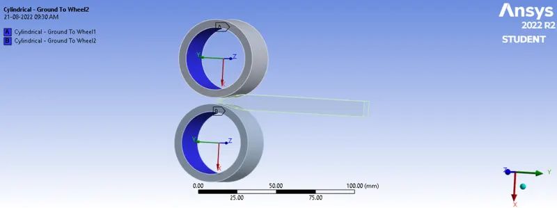
- In Joints, the cylindrical type of joint is selected for both wheels with connection type being body-ground, since the rotation is to be specified to the wheels. Below are the details of the Joints which are applied.
- Contact between Workpiece and Wheel 1:
- Meshing
The automatic mesh will be performed with Default mesh size and the mesh size is chaned to 6 mm. The mesh size of 3mm is applied to the workpiece.
The total number of nodes and elements generated are 9321 and 1629 respectively. The generated mesh can be seen below: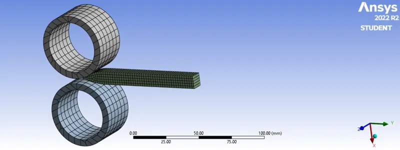

A mesh metric was used to identify elements based on their quality, and it can be observed that the elements of the lowest quality are minimum. The majority of the elements have very high quality values ranging from 8.8822e-002 to 0.99948 with an average value of 0.93498. As a result, the mesh is of good quality. - Boundary Conditions
The analysis was carried out in 14 steps and to account for large deformations, the large deflection was enabled. To provided a stabilizing force for converging against instability due to non-linearities, stabilizing energy is switched on with an energy dissipation ratio of 0.1 which is recommended for bending or extrusion application. When Stabilization is activated, it adds dampers to all the nodes. When the large displacement nodes try to move, the force is added to balance them thus favouring convergence.
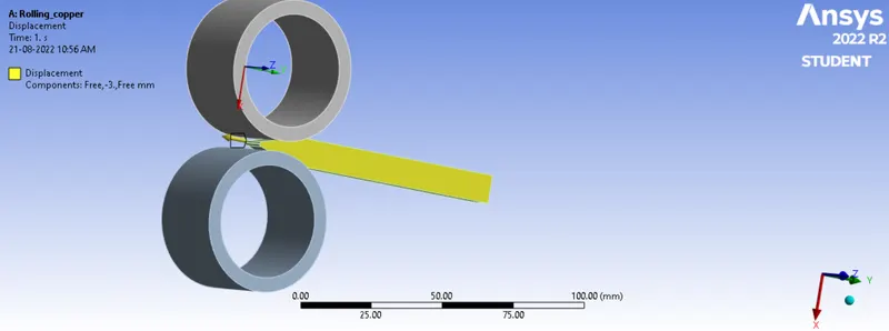
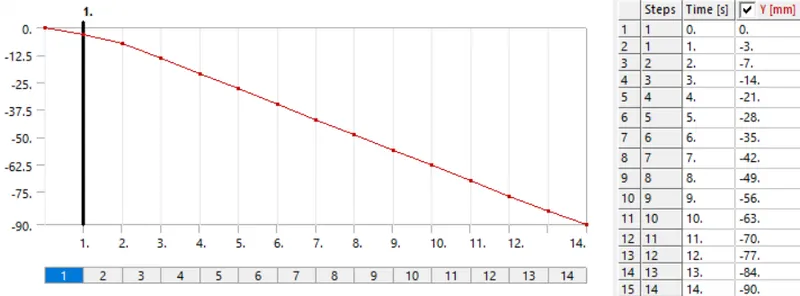
- The workpiece is provided with the displacement condition that varies almost linearly throughout the time step. It is defined in such a way that the workpiece will be displaced 90mm at the end of the final time step.
- Rotational boundary condition was defined for both the cylindrical joints in which the rotation angle varies almost nearly from 0 to 210 degrees. Also, it is ensured that both the rollers will be rotating in the opposite direction.
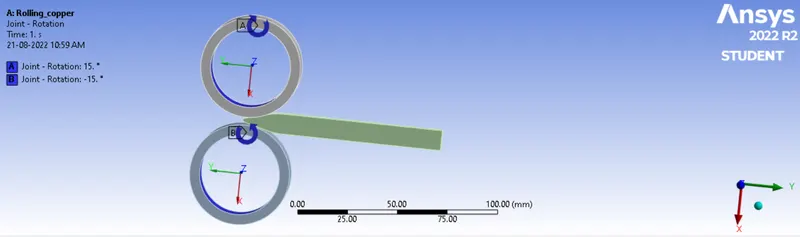
- Rotation Input for Wheel 1:
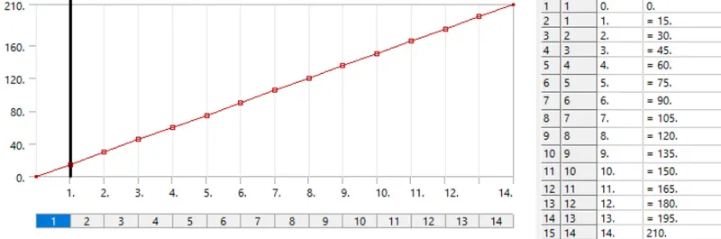
- Rotation Input for Wheel 2:
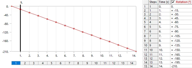
- Rotation Input for Wheel 1:
- The workpiece is provided with the displacement condition that varies almost linearly throughout the time step. It is defined in such a way that the workpiece will be displaced 90mm at the end of the final time step.
Results:
After the simulation of Rolling Operation mechanism, the following results were obtained.
- Equivalent stress for the whole setup:
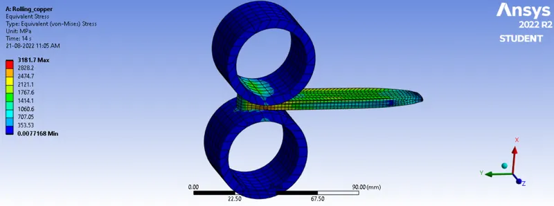
Maximum Equivalent Stress = 3181.7 MPa
Average Equivalent Stress = 910.84 MPa
Minimum Equivalent Stress = 7.7168e-003 MPa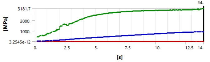
According to the findings, there is a rising tendency in the amount of equivalent stress, which eventually becomes asymptotic. The graph between Max. Equivalent stress and Time steps also shows some turbulence behavior in the initial simulation steps.
The initial rise in the equivalent stress's magnitude is attributable to the initial rise in the volume of material that is crushed in the space between the rollers. This makes more material resistant to deformation, which leads to the development of high values of Stress. Additionally, during the initial steps, the sliding contact status between the roller-workpiece interfaces induces the beginning of the turbulence behavior and promotes the formation of unstable high stresses. However, due to the accumulation of deformed material in the uncompressed side (i.e., the area just before the rotating rollers), the magnitude of stress developed increases further. This accumulation then becomes constant in the subsequent steps as this geometry becomes uniform and there are no more abrupt changes.
- Animation:
- Animation:
- Equivalent Plastic strain for the workpiece:
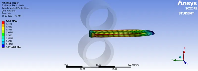
Maximum Equivalent Plastic Strain = 1.7003 mm/mm
Average Equivalent Plastic Strain = 0.96676 mm/mm
Minimum Equivalent Plastic Strain = 1.6048e-003 mm/mm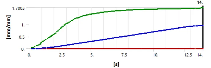
Results indicated that the development of equivalent plastic strain followed a pattern comparable to that of equivalent stress. More and more plastic deformation happens as the pressure between the gap increases, as shown in the graph.
- Animation:
- Animation:
- Directional Deformation in the Z axis for the workpiece
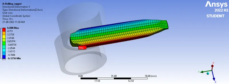
Maximum Directional Deformation in z-axis = 6.088 mm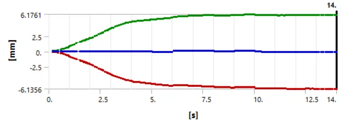
Results revealed a deformational increase in the workpiece's breadth of approximately 6 mm on both sides.
The workpiece is added to the gap between rotating rollers, leaving only the width for deformation caused by rolling operating pressure. Although deformation in the longitudinal direction is also possible, the workpiece is pushed in that direction instead, causing very little deformation in that direction.
- Animation:
- Animation:
- Prove that the workpiece has displaced by 90mm
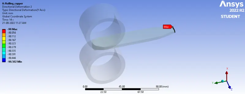
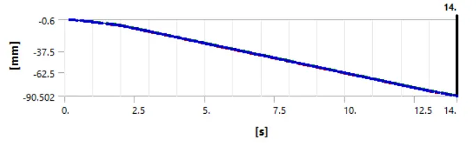
The result demonstrates the workpiece's tip's directed deformation along the lengthwise direction. The process by which deformation happens is seen to be almost identically similar to the border displacement condition, supporting the workpiece's 90 mm displacement.
- Animation:
- Animation:
Conclusion:
The work deals with the investigation of the rolling operation simulation using Ansys Workbench. The model was given the appropriate materials, contacts were then applied, and a mesh was developed. Additionally, the boundary conditions were introduced, in which the workpiece was moved up to a maximum of 90 mm, with both rollers rotated.
It was found that the whole setup has a maximum stress of 3181.7 MPa. As a result, the workpiece has undergone plastic deformation, where on the edge of the workpiece, the maximum equivalent plastic strain of 1.7003 mm/mm is observed. The lateral deformation can be seen clearly because of Poisson's ratio with a maximum laterial deformation of 6.088 mm. It has also proved from the simulation result that the workpiece was displaced by 90 mm.