ANSYS Project: Car Crash Simulation
Aim:
To perform a Explicit Dynamics analysis of a Car Crah simulation for three different values of thickness for the car body.
Theory:
A crash simulation is a computer simulation of a damaging crash test of a car or a highway guard rail system in order to assess the level of safety of the car and its occupants. Automakers utilise crash simulations for crashworthiness in the computer-aided design (CAD) process of modelling new cars during computer-aided engineering (CAE) study. At the end of a crash simulation, the kinetic energy, or energy of motion, of a vehicle before the impact is changed into deformation energy, mostly through plastic deformation (plasticity) of the car body material (Body in White).

Figure: Car Crash Test [link]
Data generated from a crash simulation reveal the capacity of the automobile body or guard rail structure to protect vehicle occupants (and pedestrians injured by a car) from injuries during a collision. Deformations (for example, steering wheel incursions) of the occupant space (driver, passengers) and decelerations (for example, head acceleration) perceived by them must fall below threshold levels set in legal car safety requirements. Today's crash simulations incorporate virtual versions of crash test dummies and passive safety systems to replicate genuine crash tests (seat belts, airbags, shock absorbing dash boards, etc.). Guide rail tests assess vehicle deceleration and rollover risk, as well as vehicle penetration of the barrier.
A form of analysis known as the Finite Element Method is used in a large number of accident simulations. Complex issues are solved by partitioning a surface into a large but still finite number of pieces and determining their motion over very short time intervals. The Macro Element Method is used in another approach to crash simulations. The distinction between the two techniques outlined above is that the structure in the case of the Macro Element Method consists of a lesser number of elements. The structure deformation computation algorithm is based on experimental data rather than partial differential equations. Pam-Crash began crash simulation and, along with LS-DYNA, is a software package commonly used for the application of the Finite Element Method. The disadvantage of this method is that it requires a large number of processing units and takes a long time to calculate. Macro Element Methodology is used in the Visual Crash Studio. It has some modelling and boundary condition restrictions as compared to FEM, but its application does not require advanced computers and the computation time is much shorter. The two strategies described here compliment one another. The Macro Element Method is useful in the early stages of the structure design process, whereas the Finite Element Method is effective in the later stages.
Objectives:
- Getting ready with the Car Crash 3D models developed in Solidworks and importing it into the Ansys Workbench for Explicit Dynamics analysis.
- Apply Boundary Conditions by setting up the contacts, Symmetry and joints. Also editing the analysis setting for the simulation to take place.
- Determine Total Deformation and Equivalent Stress for the performed simulation.
- Conducting the parametric study for different thickness value of the vehicle body.
- Analyzing the result and developing an inference for the trend shown with the change in thickness value.
Analysis Setup:
A explicit dynamics analysis is to be conducted for the car crash simulation for different body thickness value: 0.3 mm, 0.5 mm and 0.6 mm. The simulation is aimed at finding the Total Deformation and Equivalent Stresses for each case.
- Geometry:
The 3D assembly model of the Car Crash model developed in SOLIDWORKS is shown in figure below: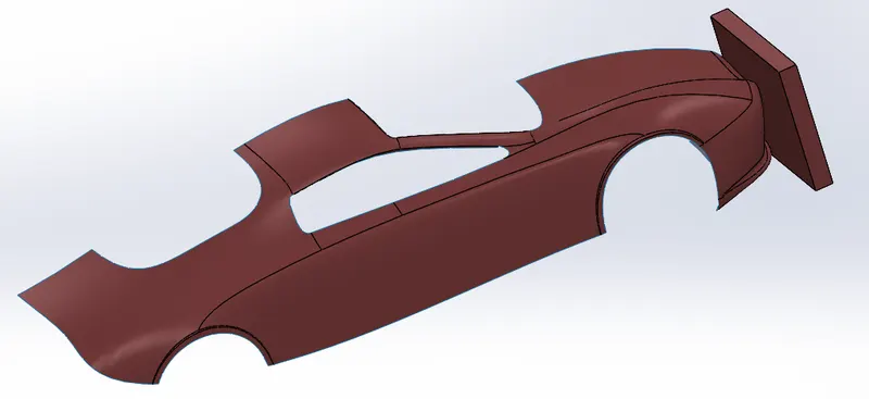
These model is then imported to Ansys Mechanical explicit dynamics Workbench for the analysis.
A material thickness to the car body is assigned. This parameter is assined for the parametric study for the camparison of results for different thickness case. - Material Properties:
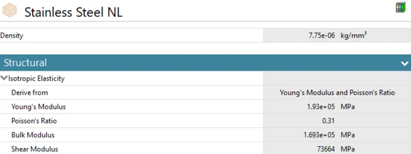
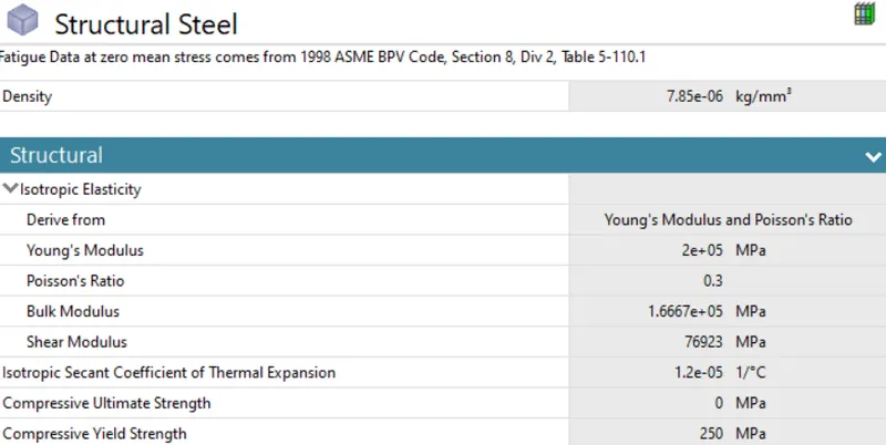
The material of the Car is kept to be Stainless Steel NL and for the Wall, the material is set to be Structural Steel for all the cases. The material properties are given below:
- Stainless Steel NL:
- Structural Steel:
- Stainless Steel NL:
- Connection Details:
The default contact identified by the workbench is deleted. The default body interactive is kept with contact detection as trajectory. Now the solver will track the trajectory of each node and face that are in initial contact or which come in contact as the solving proceeds. - Symmetry
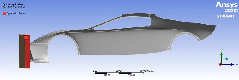
To ensure that the model actually behaves as Car (since only the one half of the car is present in the module to reduce the computational effort), a symmetry is provided to both the Wall and the Car.
- Symmetry for the Wall:
- Symmetry for the Car:
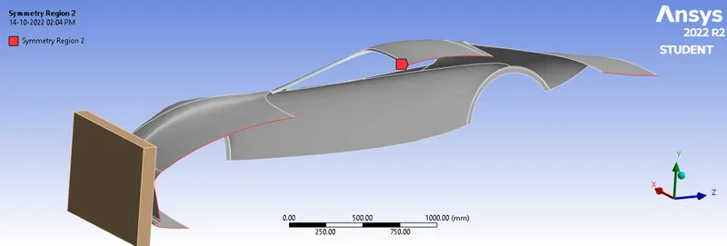
- Symmetry for the Wall:
- Meshing:
A Patch Confirming method is added to the meshing to provide the Wall the element of Tetrahedrons. For the Car, since it is a surface model, triangular elements are given by patch confirming method. A face sizing with an element size of 40 mm is provided to 11 surfaces of the rear of the Car where it will not come in contact with the Wall during Crash. Another face sizing is provided to front part of the Car (9 surfaces) with an element size of 20 mm, since it comes into contact with the wall during the Crash test. The total number of nodes and elements generated are 8219 and 23332 respectively. The generated mesh can be seen below: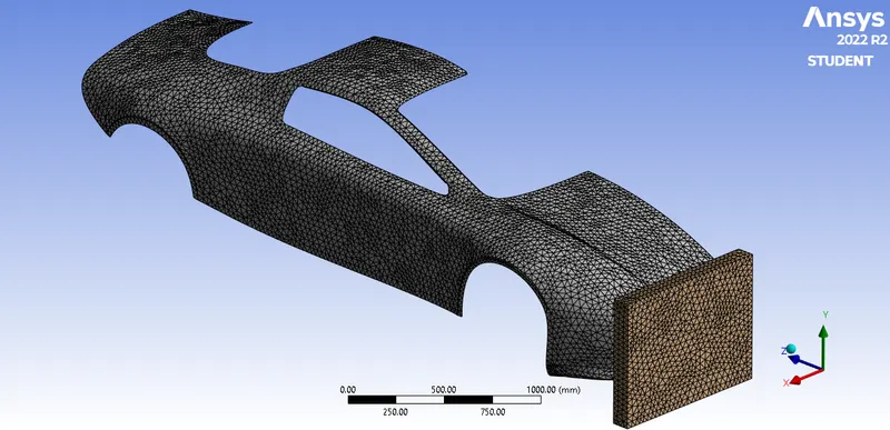

A mesh metric was used to identify elements based on their quality, and it can be observed that the elements of the lowest quality are minimum. The majority of the elements have very high quality values ranging from 0.13044 to 0.99999 with an average value of 0.84263. As a result, the mesh is of excellent quality. - Boundary Conditions:
For analysis settings, the end time is given as 0.011 s with the initial, maximum, and minimum time step be as program-controlled.
For this analysis the number of steps is set to 2 with maximum number of cycles is 1e+07 and end time is 0.001 s for the first step and it is defined by time, hence initial, maximum and minimum time will be program controlled. The maximum energy error was set to be 0.1.
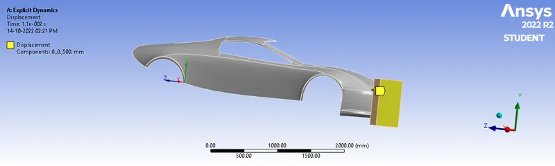
In order to simulate the motion of the model, the rear part of the car was fixed on its surface and the Wall was made to move along z-axis with a displacement of 500 mm.
- Fixed Support to the Vehicle rear part:
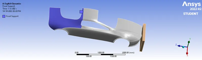
- Displacement to the Wall:
- Fixed Support to the Vehicle rear part:
Results:
In order to accomodate the comparison of different cases with different car body thickness, a parametric study was done which compares the maximum Total Deformation and Maximum Equivalent Stress.
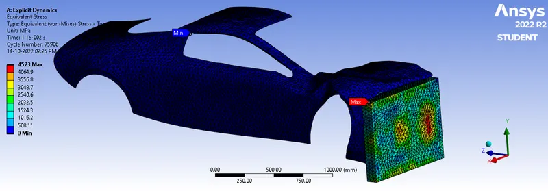
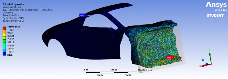
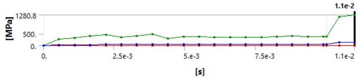
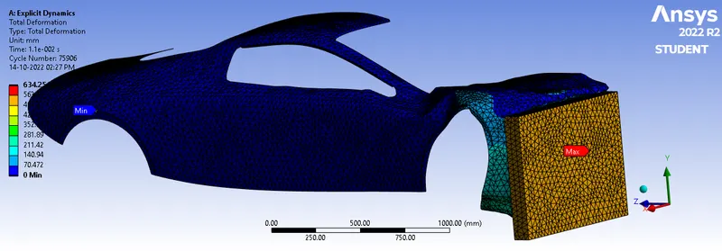
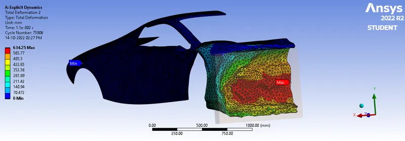
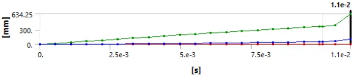
Below provides the observation for the case 1 where the Car body thickness value of 0.6 mm.
- Equivalent Stress:
- Total Deformation:
- Animations:
- Equivalent Stress:
- Total Deformation:
- Equivalent Stress:
- Comparison:
The observations from the parametric study are as below: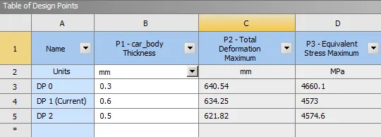
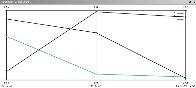
From the Parametric study table and graph above, it can be seen that with the increase of the thickness, the stress developed is decreasing. That is, the more the thickness of the vehicle body, it provides more safety for the passengers. but this have an adverse effect as well. With the increase in the thickness the mass of the vehicle increases, therby increasing the aerodynamic, acceleration, grading and rolling resistance of the vehicle which in turn reduces the efficiency of the vehicle. So assigning the thickness to the vehicle body is a trade of between the safety and vehicle performance. The parametric study as seen above can be used to find an optmized thickness. The total deformation here refers to the distance travelled by the wall. It doesn't really shows a pattern here. The more the wall moves means the vehicle has less safety as the Wall can pass through the vehicle part. But again, this analysis is done to the outer surface of the vehicle alone. But in actual scenario, there will be a lot other vehicle components as well such as engine, transmission system, etc under the front bonet that also major role identifying the safety of the vehicle during crash analysis. A further study with various other thickness value also need to be done in a parametric study in order to find the actual trend for maximum stress and deformation of the vehice body with thickness.
Conclusion:
With Ansys Workbench, a simulation of a vehicle Crash Test was conducted successfully for different vehicle body thickness cases and are compared. According to the analysis, with the increase in the thickness, the maximum stress develped decreases, which would reduce the damage of the vehicle, which in turn provides more safety for the driver and passenger. But increasing thickness would increase the weight of the vehicle which would decrease the performance of the vehicle.