ANSYS Project: Wire Bending
Aim:
To perform a static structural analysis of the bending of wires for different material cases.
Theory:
Wire forming is a method for applying force to change the contour of wire by bending, swaging, piercing, chamfering, shearing, or other techniques. Any shape, form, or arrangement can be produced using one of the several wire forming procedures. A coil of wire is first produced, then it is straightened to begin the process.
Although a variety of tools are used to produce wire, wire forming machines are typically controlled manually or mechanically. Both mechanical and electrical machines that require manual loading fall under the category of manual machines. Production is completed by automatic machines with sophisticated computer numerically controlled (CNC) programming.
- Manual Wire Forming: Using a hand lever and spindle, manually operated devices are the most traditional means of producing wire. Manual machines with gears that increase the applied bending force might be drawing or rotary die machines.
- Coil Wire Forming: Winding wire around a metal blank is known as coiling or spring wire shaping. Additionally, it is employed in the production of electrical coils, which consist of a conductive wire uniformly looped around a ferromagnetic core. Depending on the finished product, coil winding can take many different forms. Unlike springs, electrical coils must be twisted more accurately and may require multiple windings.
- Roll Wire Forming: For producing flat, rounded, and various shapes of wire parts, roll forming is a practical and affordable technique. Undercuts, knurls, pointing, chamfers, grooves, surface finishes, collars, and threads can all be produced using this method. Roll-formed wire components with rounded edges, pre-finishing, and hardening offer increased tensile strength.
- Bend Wire Forming: The wire can be bent in an infinite number of configurations during the wire bending process to suit any application. It is simple to manufacture diameters ranging from 0.4 mm to 16 mm, or 0.016 to 0.625 in. Since the wire is bent before it is cut, there is no waste or scrap created during the operation, so additional finishing is not required.
- Four-slide Wire Forming: With the inclusion of cams, fourslide shaping or stamping uses the same method as a horizontal stamping press. The machine also includes shafts, an electric motor, a die, a press, and sliding tools in addition to the cams. The wire is formed using four sliding tools during the operation. The cam controls the motion of the four tools, enabling the process to move vertically—for example, when punching—and horizontally in a number of directions.
- Hydraulic Wire Forming: In a hydraulic wire forming machine, the shaping rollers are driven by a hydraulic motor. The machine is programmed to the desired configuration using a servo motor and CNC programming. After the procedure is finished, the machine automatically discharges the wire shapes.
- Pneumatic Wire Forming: Wire is fed into the straightening machine pneumatically, molded into the desired shape, and then cut to the needed length.
- CNC Wire Bending: Pneumatic or hydraulic CNC wire bending equipment are available for effective and quick manufacturing. Rebar can be bent and shaped to an angle of 180° using a single or two wires. The bar is straightened by the machine before it is bent. With their extraordinary accuracy, CNC machines can precisely cut wire to the desired dimensions. Music wire, hard drawn wire, basic or coated metals, 300 series stainless steel, brass, and beryllium copper are among the sorts of wire that a CNC machine can be taught to shape. The range of wire sizes is 0.008 to 0.250 in, or 0.0203 mm to 6.35 mm.
A Bending Machine is a tool for forming. It is used to put together a bend on a workpiece. A bend is created by moving linearly or rotationally while using a bending tool. Kinematics can be used to perform a detailed classification.
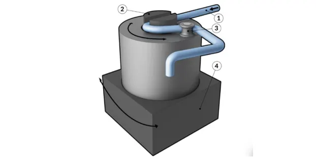
A metal wire (1) workpiece is run through a split die (2) that has been modified with bending pins that are appropriate for the desired bending forms. The wire is bent around the die by the rotary bending tool (3), which causes plastic deformation. The wire is then raised to the following bending position. All possible bends are possible thanks to the ability to spin the entire bending anvil (4) around the wire axis.
By cutting the wire where it is needed, the finished portion is released. To change the bending radius or enable more sophisticated bends, many bending machines include the ability to swap between various sets of bending tools.

Objectives:
- Getting ready with the Wire Bending 3D models developed in Solidworks and importing it into the Ansys Workbench for static structural Analysis.
- Apply Boundary Conditions by setting up the contacts and joints. Also editing the analysis setting for the simulation to take place step by step.
- Determine Equivalent Stress and Equivalent Elastic Strain of the Wire results for the performed simulation.
- Repeating the Simulation for other Wire Materials
Analysis Setup:
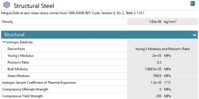
A static structural analysis is to be conducted for the wire bending setup for three different wire materials. The material of Support and Lever is set to be structutal steel for the whole analysis.
- Geometry
The 3D assembly model of the wire bending mechanism developed in SOLIDWORKS is shown in figure below: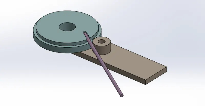
These models are then imported to Ansys Mechanical Static Structural Workbench for the analysis. - Material Properties
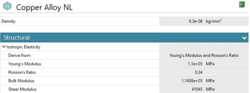
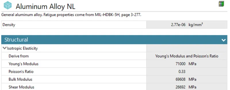
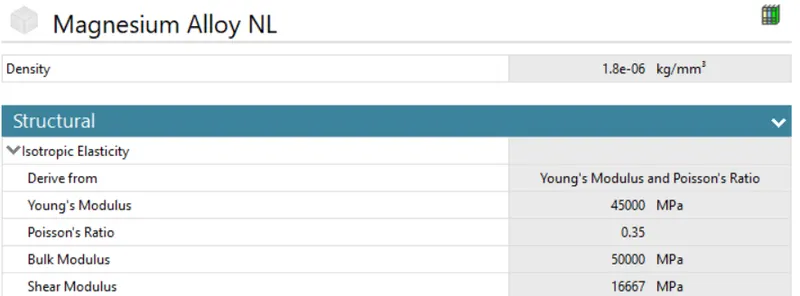
The material of Support and Lever is set to be structural steel for all the analysis. For the first case, analysis is done for the sheet with materials Copper Alloy. Then the analysis is repeated for the materials Aluminum Alloy and Magnesium Alloy. The material properties are given below:
- Copper Alloy
- Aluminum Alloy
- Magnesium Alloy
- Structural Steel
- Copper Alloy
- Contact Details
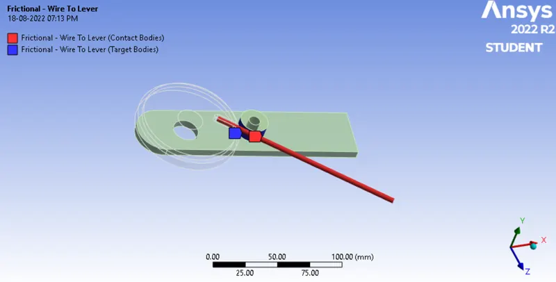
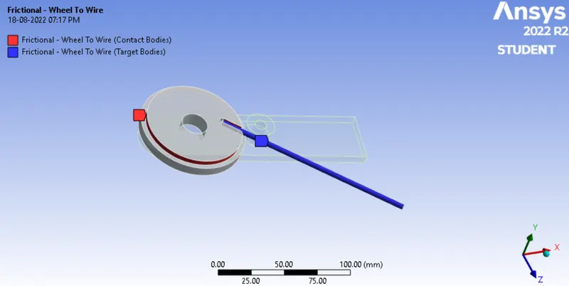
Frictional contacts are established between interfaces of wire pieces and lever with frictional coefficients of 0.2. The formulation method is Augmented LaGrange, Normal stiffness as a factor 0.1, update stiffness at Each iteration, and interface treatment as Add offset. Similar contact is also made between contact regions of the wire piece and the support. Below are the details of the contacts which are applied.
- Contact between Wire and Lever
- Contact Between Wire and Support
- In joints in order to perform bending action, a revolute joint is applied to the lever hence able to rotate in its position and perform bending operations.
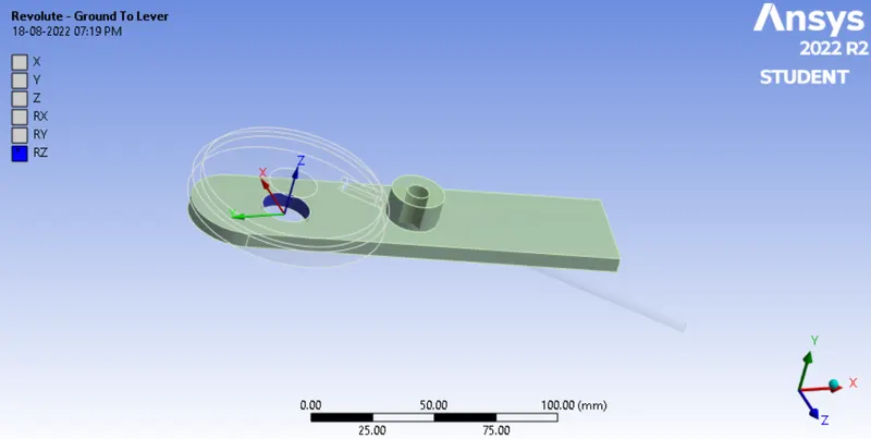
- Contact between Wire and Lever
- Meshing
This component is a solid part, tetra mesh can be generated, and to have the accurate result the mesh is refined at the wire and bending source by giving the face sizing. First, the Patch conforming method is inserted by selecting all three bodies and methods as Tetrahedrons. The face sizing 1 with selecting 4 faces and element size 2.2 mm. In order to further improve the meshing in the contact region between support and wire, a face sizing 2 was introduced. The face sizing 2 with selecting wire face, sphere radius 7mm, and element size 0.8mm. A new co-ordinate system was made to fix the centre of the sphere for face sizing 2.
The total number of nodes and elements generated are 8118 and 4073 respectively. The generated mesh can be seen below: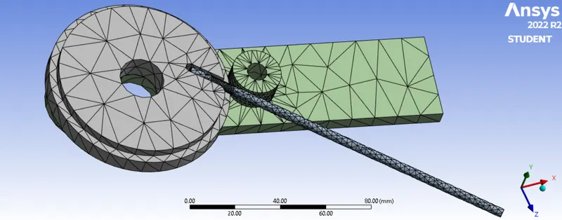

A mesh metric was used to identify elements based on their quality, and it can be observed that the elements of the lowest quality are minimum. The majority of the elements have very high quality values ranging from 0.11935 to 0.99987 with an average value of 0.69965. As a result, the mesh is of reasonable quality. - Boundary Conditions
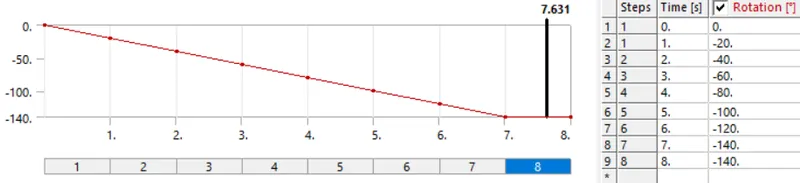
A total of 8 steps are provided to run the simulation but step 1 has different parameters with an initial time step 0.1 s, minimum, time step 1e-002 s, and final time step 0.2 s. From step 2 to 8 as carryover, the time step is ON with minimum time step is 1 e- 002 s and maximum time step 1 s.
The fixed support is given to the wheel which is connected to a wire and another fixed support to the top of the wire so while bending it should not get outside of the process to fail the simulation. These joints are as shown below:
- Fixed Joint at the end of the wire
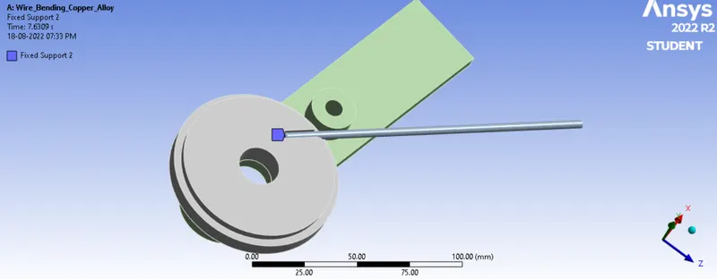
- Fixed Joint for the Wheel
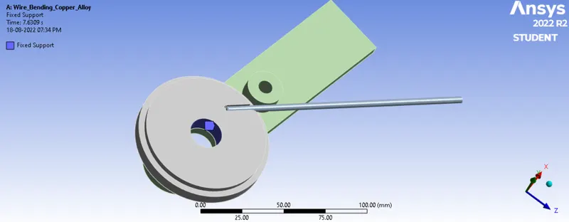
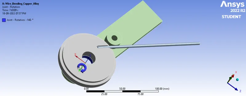
- A Joint Rotation is provided to the Lever to replicate its actual movement as shown below:
-
In order to save computational time and aid in easy convergence, various changes have been made and are summarized below:
-
Eight-time steps are used to simulate the bending action.
-
The solver type is changed to direct rather than iterative.
-
Weak spring and large deformation settings are enabled to counter unconstrained motion and deformations.
-
Automatic time settings are also enabled to help in easy convergence by processing the simulation in a small sub time steps increments inside each time steps.
-
- Fixed Joint at the end of the wire
Results:
- Case 1: Wire material as Copper Alloy
The outputs obtained for Case 1 is provided below:
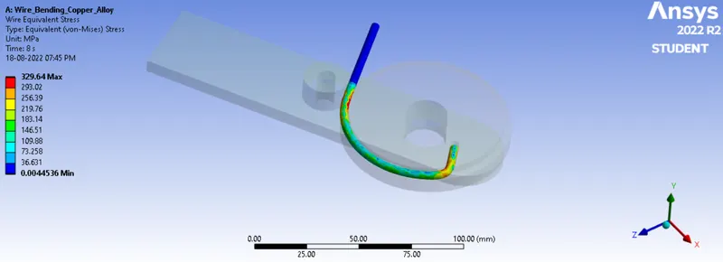
- Wire Equivalent Stress:
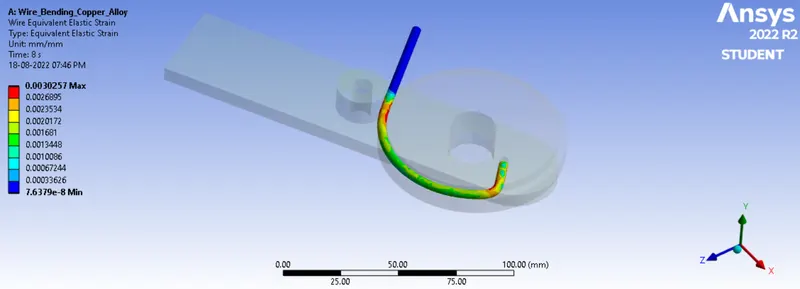
- Wire Equivalent Elastic Strain:
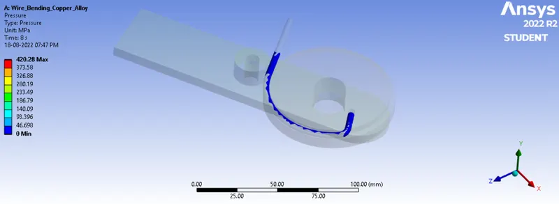
- Contact Tool: Pressure
- Animation:
- Wire Equivalent Stress:
- Case 2: Wire Material as Aluminum Alloy
The outputs obtained for Case 2 is provided below:
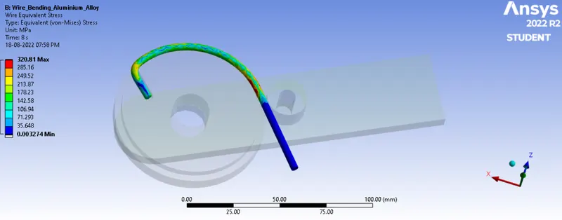
- Wire Equivalent Stress:
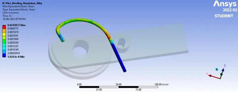
- Wire Equivalent Elastic Strain:
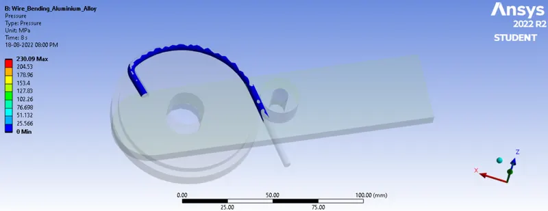
- Contact Tool: Pressure
- Animation:
- Wire Equivalent Stress:
- Case 3: Wire Material as Magnesium Alloy
The outputs obtained for Case 3 is provided below:
- Wire Equivalent Stress:
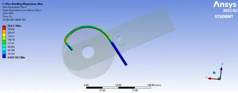
- Wire Equivalent Elastic Strain:
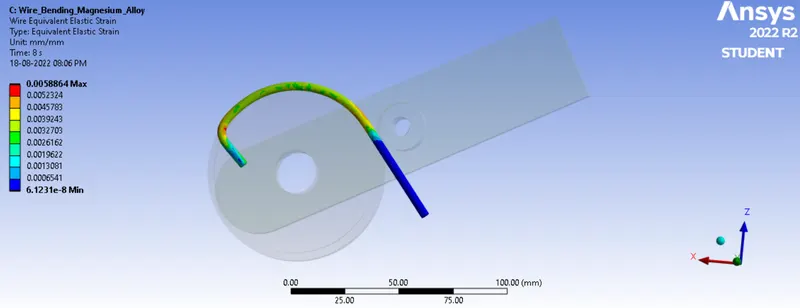
- Contact Tool: Pressure
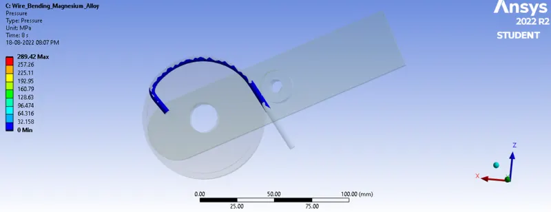
- Animation:
- Wire Equivalent Stress:
- Comparison of the Cases
The Equivalent Stress and Equivalent Elastic Strain of the wire for each case is summarized in the table below:
Maximum Wire Stress Maximum Wire Elastic Strain Case 1: Copper Alloy 329.64 MPa 3.0257e-003 mm/mm Case 2: Aluminum Alloy 320.81 MPa 4.5872e-003 mm/mm Case 3: Magnesium Alloy 264.17 MPa 5.8864e-003 mm/mm
From the above table, it can be inferred that the maximum equivalent stress is generated in copper alloy with a value of 329.64 MPa. The least equivalent stress is obtained in magnesium alloy with a value of 264.17 MPa.
The strain is almost the same for all the three materials. The maximum value of strain is observed in Magnesium alloy with a value of 5.8864e-003 mm/mm.
Conclusion:
As can be seen from the animation, the wire is under the most strain close to the corner of the wheel's wire slot. Compared to the former section, the wire's remaining portion does not experience as much plastic deformation.
The degree to which an object resists deforming in response to an applied force is referred to as its stiffness. A material's stiffness value is higher for materials with a higher elastic modulus. This is the cause of the increased level of stress that copper alloys undergo.
As noted in the table, magnesium alloy wire is a good option because it is more flexible than the other two and has a lower elastic modulus. Additionally, other elements like specimen length and cross-sectional area impact the material's stiffness. However, because the cross-section and length are constant in this study, the equivalent stress and equivalent strain values are the main factors to consider.
However, the material must be chosen in accordance with the type of application. When choosing a wire application, for instance, consideration must be given to aluminum and copper wire. Therefore, it can be concluded from these simulation results that magnesium alloy can be twisted into wires more easily than aluminum alloy and copper alloy.