SOLIDWORKS Project: Sunseeker Predator Yacht [Design and Photo Realistic Rendering]
Design and Photo Realsitic Rendering of Sunseeker Predator Yacht using SOLIDWORKS
Aim:
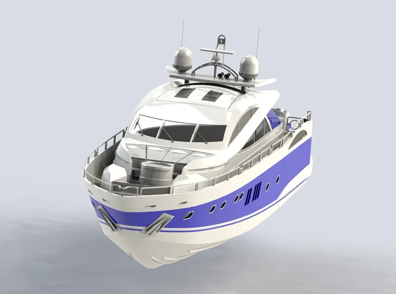
To design an Sunseeker Predator 108 Yacht in SOLIDWORKS and to do a photo realistic rendering.
Introduction:
A Yacht is a sail or power vessel used for pleasure, cruising or racing. There is no standard definition, so the terms applies to such a vessels that have a cabin with amenities that accomodate overnight stay. The design considerations of a cruising yacht include sea worthiness, performance, sea kindliness, and cost of construction.
The seaworthiness addresses the integrity of the vessel and its ability to stay float and shelter its crew in the conditions encountered. Performance hinges on a number of factors including the waterline lenth (longer means faster), drag in the water (narrow hull with smooth appendages), hull shape and sail shape and area. Sea kindliness is an indicator of steering ease, directional stability and quelling of the motion induced by wind and waves.
Multihull offer tradeoffs as cruising sailboats, compared with monohulls. They may be catamarans or trimarans. They rely form stability - having separate hulls far apart - for their resistance to capsize. Their advantages include greater stability, speed, (for catamarans) living space and shallower draft. Their drawbacks include greater expenses, greater wind age, more difficult tacking under sial, less load capacity, and more maneuvering room required because of their broad beam. They come with a variety of sleeping accomodations and (for catamarons) bridge-deck configurations.
Objectives:
- To create the model of individual parts of Yacht in part modeling environment using SOLIDWORKS.
- To assemble created models of invidual parts of Yacht in the assembly environment.
- To create a photo realistic model of the Yacht and render it in SOLIDWORKS Photoview 360 and SOLIDWORKS Visualize.
Design Methodology / Approach:
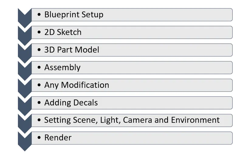
A typical Sunseeker Predator Yacht consist of large number of parts. Since the cosmetic model of Sunseeker Predator Yacht is to be designed, focus is done mainly on the prime parts and designing them. Once all parts are modelled, they need to be assembled in the assembly environment. After the assembly is done, rendering of the Yacht is done in render tools like Photoview 360 and SOLIDWORKS Visualize.
Part Modeling:
In general, modeling entails creating a virtual prototype of an object. It may be used for a variety of things. Consider a car's engine, which includes hundreds of components. Each component may be modelled independently and then integrated to generate the engine's final shape. Part Modelling is the name given to this form of modeling.
Assembly:
An assembly is a grouping of individual model pieces that are combined in an assembly environment to form a bigger, more complicated product representation.
- Assembly Modeling Approaches
- Bottom-Up Assembly Approach
Individual parts are made separately, integrated into the assembly, and positioned and orientated (using mating conditions) as specified by the design. If the pieces have already been built, the bottom-up method is the preferable option (off the shelf). It enables the designer to concentrate on the individual components. It also makes it easier to preserve the top-down approach's connection and regeneration behavior of the pieces. - Top-Down Asembly Approach
The assembly file is prepared initially using an assembly layout sketch in this method. The components are created in the assembly file, or the concept drawings for the parts are entered and finished there. In other words, the final geometry of the pieces was not determined before they were included to the assembly file. The method is perfect for huge assemblies. - The Middle Out Approach
The bottom-up and top-down assembly modeling methodologies are combined in the middle-out assembly modeling methodology. This sort of assembly model is often built with the majority of the parts already produced and new parts planned and created utilizing the assembly for building information.
- Bottom-Up Assembly Approach
Design and Modeling:
The individual parts of the Sunseeker Predator Yacht was modelled either using Surface modeling or using Solid modeling or both.
- Tools and Features Used
- Extruded Surface: It is used to extrude sketch contours on one or two direction to create a surface.
- Lofted Surface: It is used to create a surface between two edges or sketches.
- Fill Surface: It is used to fill the gap between edges. It is similar to lofted surface only difference is, it requires closed area while lofted surface can be used with open area.
- Trim Surface: It is used to remove the extra surface from the intersection betweeen two surfaces ot surface and plane or surface and a sketch.
- Extended Surface: Tool to perform function like extending the one of the surfaces at intersection.
- Knit Surface: It is used to combine two or more surface together and make them single surface.
- Extrude Boss: Extrude Boss is a feature that allows us to transform 2D designs to 3D by adding thickness in the third dimension.
- Revolved Boss: It is used to generate a solid 3D model centered on an axis. You may add materials to the drawing by rotating it around an axis.
- Sweep Boss/Cut: By sweeping a totally closed profile down a route, it is possible to add or remove material from a solid model or part. Swept Boss or Base-up adds solid material to the design's body, whereas Swept Cut removes material from the design's body.
- Fillet: Fillets are used to round off the edges and/or corners of objects. Fillet adds or subtracts material depending on whether the edge is internal or exterior in order to round edges or corners. There are manual fillet and fillet expert options available, depending on the intricacy of the model or the number of models to fillet.
- Shell: The shell tool hollows down a component, leaving the selected faces exposed, and creating thin-walled features on the remaining faces.
- Loft Boss / Loft Cut: A loft is made up of two or more profiles. Points can only be assigned to the first, last, or first and last profiles.
- Linear Pattern/Circular Pattern/Curve Driven Pattern: It is used to generate numerous instances of one or more characteristics that can be evenly spaced along one or two linear or circular pathways. In a linear pattern, we must choose the linear path pattern that must be followed. In a circular design, we must choose which circular direction the pattern should take. We have chosen the curve along which the pattern must be followed in a curve-driven pattern.
- Mirror: It enables us to reproduce features in the same way that the mirror image does. We can reflect features along a plane, an axis, a face, reference geometries, and so on. We can also reflect patterns, bodies, and multi bodies, which makes creating more easier.
- Projected Curve: This tool is highly handy for creating complicated 3D curves. Using this tool, drawing curves in multiple planes with certain common points and merging them helps to produce smooth 3D curves.
- Split: The split tool operates in the same way as the extruded cut tool, but it provides a lot more possibilities for cutting out portions. It is useful for cutting off intersecting portions and removing unneeded interior or external pieces.
- Reference Geometry: The shape or form of a surface or solid is defined by reference geometry. Planes, axes, coordinate systems, and points are examples of reference geometry.
- Mates: Mates establish geometric links between the many elements we created. It aids in the creation of various mates with concentric, parallel, perpendicular, tangent, and other relationships.
- Description of Parts and Features Used
- Hull:
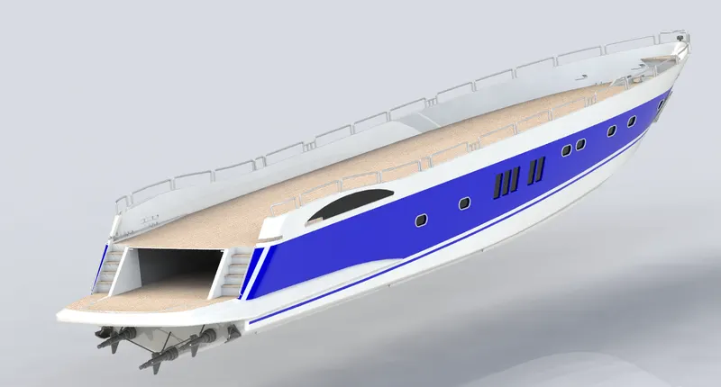
A hull is a watertight body of the ship or boat. The hull may open at the top and it may be fully or partially covered with a deck. At the top of the deck may be a deckhouse and superstructures, such as a funnel, derrick, or mast. The line where the hull meets the water surface is called waterline. The design of the hull involves the preparation of the outer shell surface and the deck surface. The outer hul is drafted with hte required curves initially and are extruded and lofted to obtain the required surface. The curves are drawn at different planes and they are projected so that the required curvature is obtained in between the planes.
Commands used: Surface loft, surface trim, surface knit, boss extrude, cut extrude, convert entities, sweep, helix/spiral.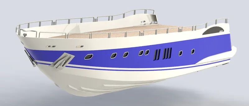
- Superstructure:
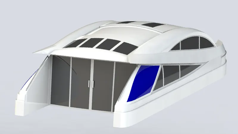
Superstructure is a multibody part which consist of cockpit, Table, viper, and window. This is the most complicated part of the whole yacht to design.
Commands used: surface loft, surface trim, surface knit, surface fill, extended surface, mirror, and ruled surface.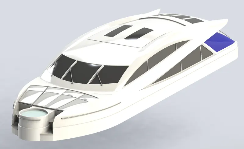
- Front, Middle and Rear Seats:
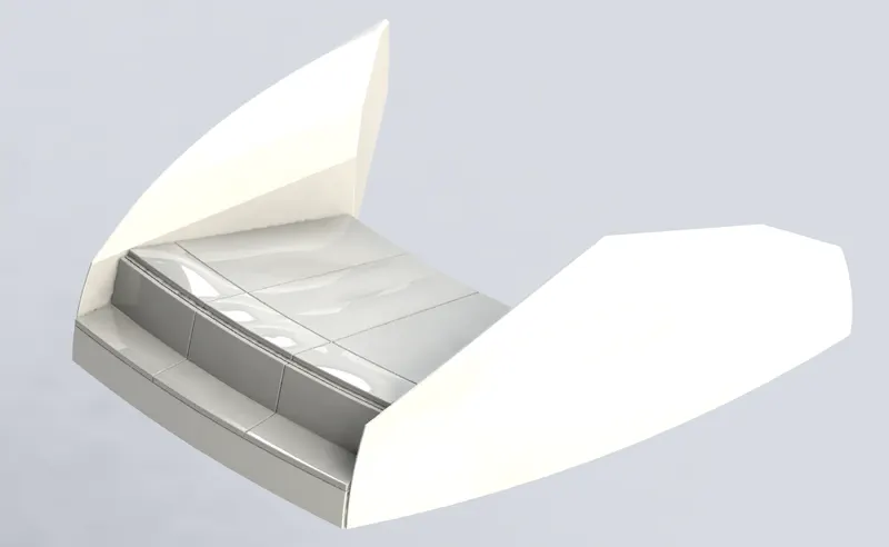
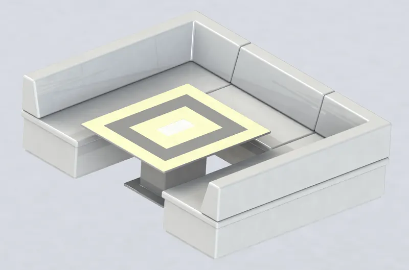
These are the accessories of the Yacht for resting and sitting.
Commands used: Surface loft, Surface trim, Surface Knit, Cut Extrude, Dome.
- Front Seat
- Middle Seat
- Rear Seat
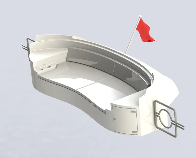
- Front Seat
- Radar and Radar Mast:
Marine radars are used to detect other ships and land obstacles to provide bearing and distance for collition avoidance and navigation at sea. They are electronic navigation instruments that use a rotating antenna to sweep a narrow beam of microwaves around the water surface surrounding the ship to the horizon, detecting targets by microwaves reflected from them, generating a picture of the ship's surrounding on the display screen.
Commands used: Revolve, Shell, Extrude Fillet
- Radar Mast
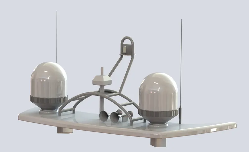
- Radar
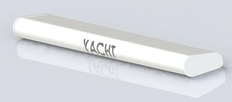
- Radar Mast
- Garage Door:
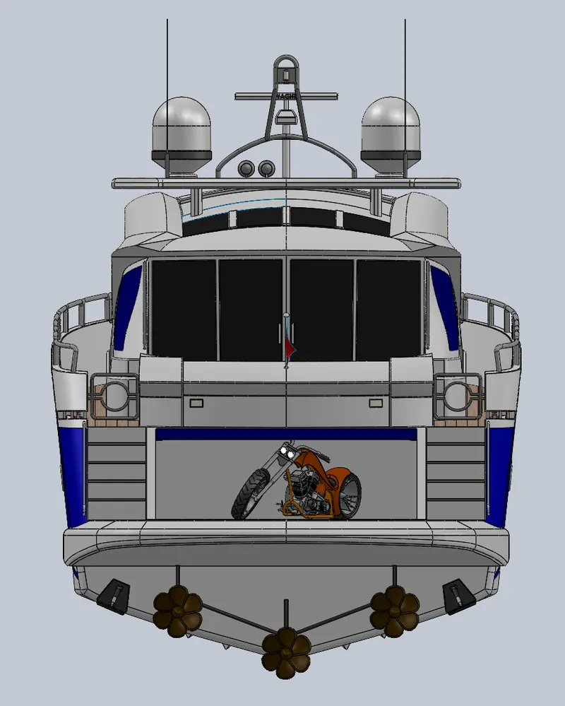
Garage door is the part that is extracted from the hull structure rear part using usin the split entities option. It is then edited to fit in the hull a cover or door to the garage space created for storing the equipements or vehicles.
Commands used: Split entities, Cut extrude, Fillet.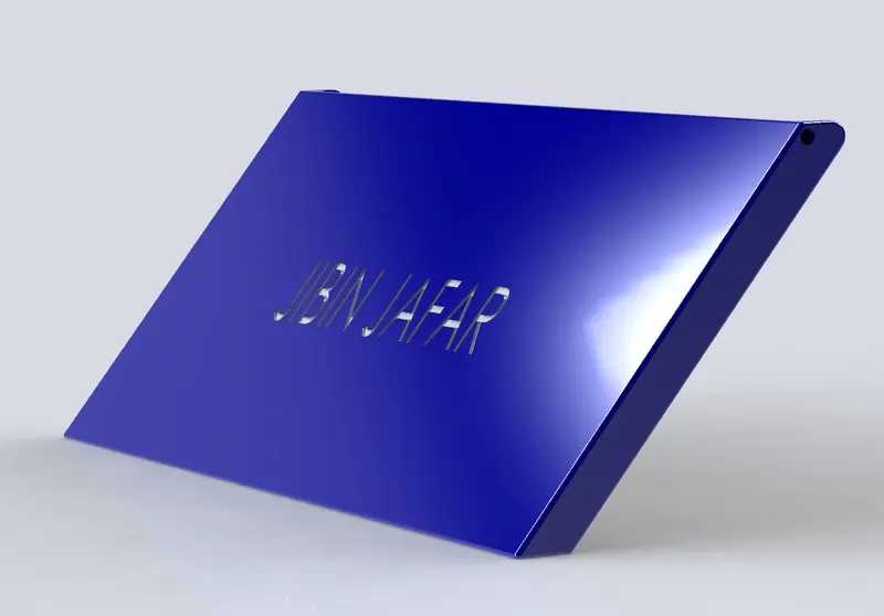
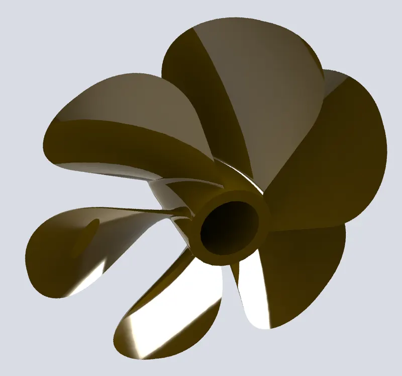
- Propeller:
Propeller is responsible for the high speed motion of the Yacht. Due to the pressure difference created by the blades, the Yacht moves forward in the water.
Commands used: Revolve, Loft, Fillet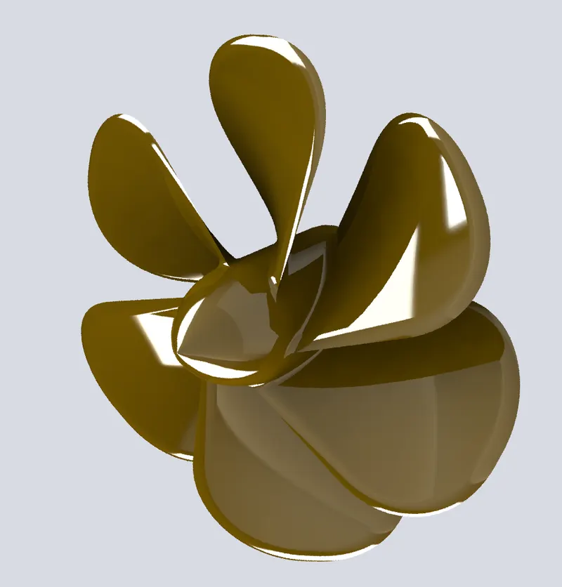
- Hull:
- Assembly
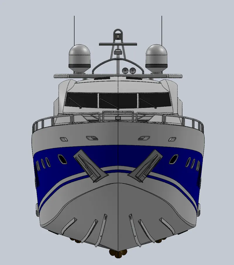
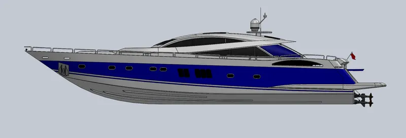
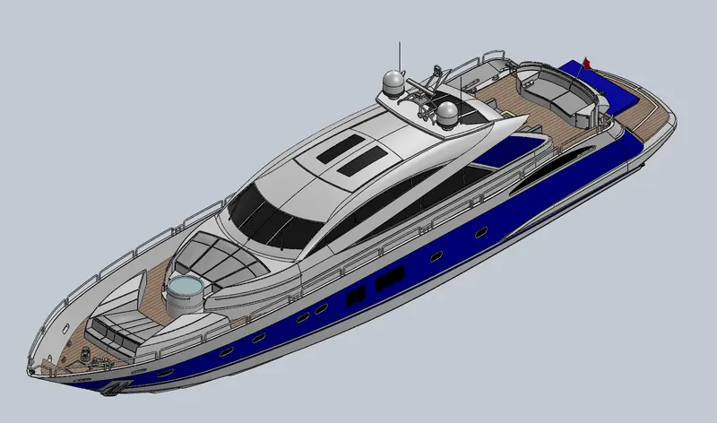
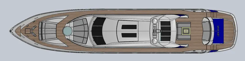
All the modelled parts were inserted one by one in the assembly environment and mates were applied to fix their positions.
Mates build geometric relations between components of the assembly. The permissible paths of linear or rotational motion of the components can be defined as the matches are added. Inside their level of independence, a part may be transfered, visualizing the assembly's behaviour.
Types of Mates
Standard Mates: Angles, Coincident, Concentric, Distance, Lock, Parallel, Perpendicular, Tangent Mates.
Advanced Mates: Limit, Linear/Linear Coupler, Path, Symmetry, Width Mates.
Mechanical Mates: Cam-Follower, Gear, Hinge, Rack and Pinion, Screw, and Universal Joint Mates
- Front View
- Side View
- Isometric View
- Camera Setup View
- View 1
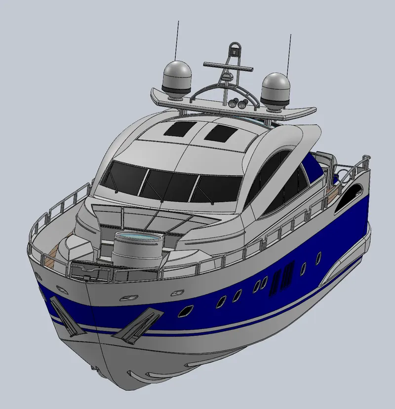
- View 2
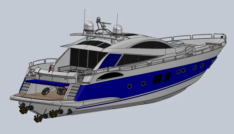
- View 1
- Top View
- Front View
- Rendering
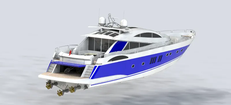
Rendering is the process of creating realistic images with the photo realsitic environment. Rendering has been done in two ways in SOLIDWORKS:
1. Photoview 360
2. SOLIDWORKS Visualize
In the photo realistic model, some of the mate conditions and positions were changed to render realsitic models. Then the photorealistic model is rendered into realsitic images with different views.
- Rendering Done in Photoview 360
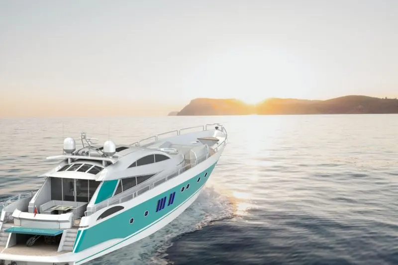
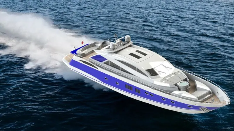
- Rendering Done in SOLIDWORKS VISUALIZE
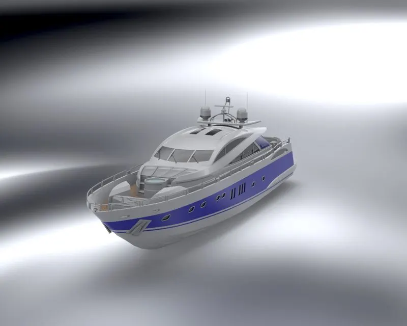
- Rendering Done in Photoview 360
Conclusion:
All the parts of the Sunseeker Predator Yacht were modelled and the assembly was created using SOLIDWORKS. The photo realistic renders of the Yacht was then created on SOLIDWORKS Visualize.
Downloadble Link:
The zip file of the complete assebly can be downloaded from:
https://drive.google.com/file/d/151e3cMt1D91YwEyOPcjhxu7NBPT19UYn/view?usp=sharing