ANSYS Project: Machining with Planer
Aim:
To perform a Explicit Dynamics analysis of the mechanism "maching with planar" for two different velocity cases of the tool.
Theory:
In high-mix/low-volume general machining job shops, automotive parts suppliers, and other commercial parts suppliers, high-speed machining has continued to advance. High-speed machining in this market category was defined in the 1990s as cutting parts with spindle speeds over 10,000 RPM, allowing for faster metal removal rates. High-speed machining is becoming increasingly sophisticated, with a greater emphasis on all aspects of the cutting process.
Figure: Slotting Machine [Technology Student, link]
Machine tool design advancements have increased the overall rigidity of the machine frame, reducing vibration during cutting. When more aggressive cutting parameters are applied, this provides for even chip load in the cut and a reduction in noise. Furthermore, most new spindles are direct drive, which removes gear boxes and improves spindle dynamics. Makino spindles have evolved over the years by producing great power and torque, allowing for aggressive metal removal by improving horsepower/torque curves.
Some machine tools, such as the Makino 1-Series horizontal machine centres, lack the axis and spindle stiffness required for high-speed machining. To overcome this limitation, a CNC milling technique known as "trochoidal milling" was created. Trochoidal milling is a roughing and semi-roughing technique that takes huge axial depths of cut by attacking with multiple high-speed arcing passes that cut a modest radial depth of cut with each pass. This results in reduced radial cutting forces, less vibration, and less heat in the cutting zone. This necessitates the use of a machine control with sufficient processing capacity to sustain the tool's continually changing feed rate as it moves along its circular path.
Computing power, like in many other aspects of manufacturing, has enabled advancements in high-speed machining. It has resulted in the ability to cut parts faster while maintaining good quality. Modern CNC controllers are capable of maintaining a steady feed rate, resulting in a consistent cutting load. This enhances surface quality and tool life while allowing for shorter cycle durations. Because powerful controllers can see ahead in a programme, software may optimise tool routes for speed and precision. This is only possible now because of advances in high-speed programme data storage and quicker data transmission rates.
Improvements in machine structure design, spindle technology, and computer hardware/software have increased machine tools' high-speed machining capabilities over the previous few decades, allowing for higher metal removal rates and shorter cycle durations.
Objectives:
- Getting ready with the Machining with Planar 3D models developed in Solidworks and importing it into the Ansys Workbench for Explicit Dynamics analysis.
- Apply Boundary Conditions by setting up the contacts and joints. Also editing the analysis setting for the simulation to take place.
- Determine Total Deformation, Equivalent Stress and User defined result to measure temperature for the performed simulation.
- Conducting the parametric study for other cutting tool velocity.
- Analyzing the result and developing an inference for the trend shown with the change in cutting tool velocity.
Analysis Setup:
A explicit dynamics analysis is to be conducted for a machining with planar machine for two different cases of cutting tool velocity: 20,000 mm/s and 15,000 mm/s. The simulation is aimed at finding the Equivalent Stress, Total Deformation and also User defined result to calculate the temperature of the body for the two cases.
- Geometry:
The 3D assembly model of the machining with planar mechanism developed in SOLIDWORKS is shown in figure below: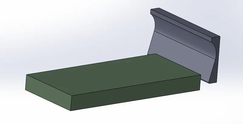
These model is then imported to Ansys Mechanical explicit dynamics Workbench for the analysis. - Material Properties:
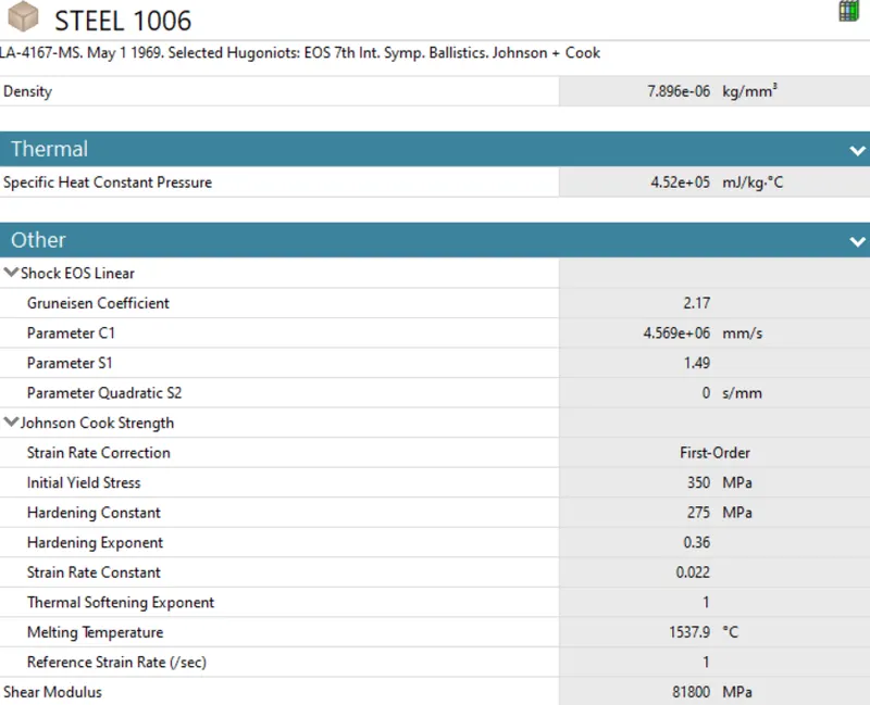
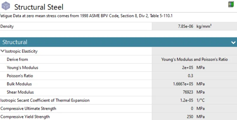
The material of workpiece is set to be Steel 1006 and that of the Cutting tool is set to be Structural Steel for both the cases. The material properties are given below:
- Steel 1006:
- Structural Steel:
- Steel 1006:
- Connection Details:
The default contact identified by the workbench is deleted as the interaction between the workpiece and the cutting tool is not a major concern for this study. Also, the body interactions is set to be frictionless. - Meshing:
An edge sizing of 10 divisions were allocated to the four corners of the workpiece thus leading to the formation of uniform element for the rectangular workpiece. For the Cutting Tool, a patch confirming technique is provided with the element method of Tetrahedrons due to its complicated shape. The total number of nodes and elements generated are 6557 and 10077 respectively. The generated mesh can be seen below: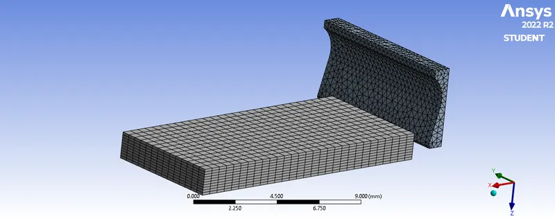

A mesh metric was used to identify elements based on their quality, and it can be observed that the elements of the lowest quality are minimum. The majority of the elements have very high quality values ranging from 0.31318 to 0.99983 with an average value of 0.68122. As a result, the mesh is of good quality. - Boundary Conditions:
For analysis settings, the end time is given as 0.00075 s with the initial, maximum, and minimum time to be as program-controlled.
For this analysis the number of steps is set to 1 with maximum number of cycles is 1e+07 and end time is 7e-4 and it is defined by time, hence initial, maximum and minimum time will be program controlled. The maximum energy error was set to be 2.
In order to simulate the motion, the workpiece was fixed on its bottom surface and the Cutting tool was made to move along x-axis with appropriate velocity for each case.
- Fixed Support to the Workpiece:
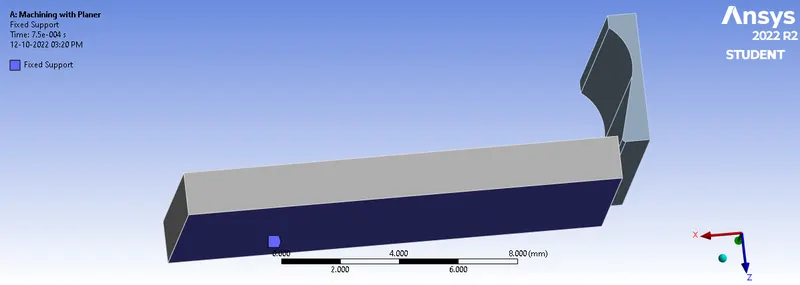
- Velocity for the Cutting Tool:
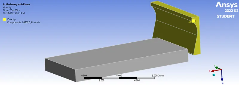
For the case 1, the velocity was set to be 20,000 mm/s and a parametric study was done for the case 2 with the cutting tool velocity of 15,000 mm/s.
- Fixed Support to the Workpiece:
Results:
In order to accomodate the comparison of different cases with different cutting tool velocity, a parametric study was done which compares the maximum Total Deformation, Maximum Equivalent Stress and Maximum Temperature.
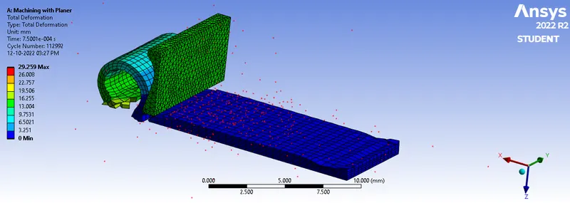
Below provides the observation for the case 1 where the velocity of the cutting tool is 20,000 mm/s.
- Equivalent Stress:
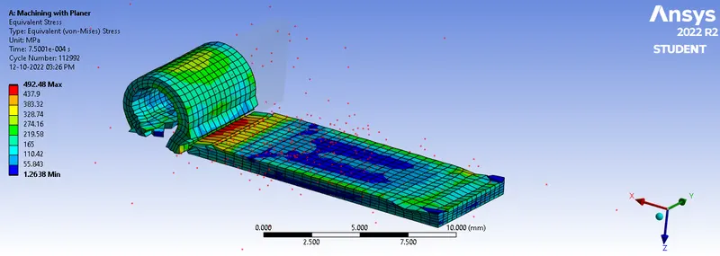
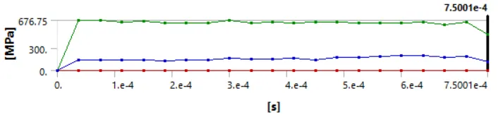
The maximum stress at the end is 492.48 MPa. According to the plots and data, we can observe that once the amount of stress hits 676.75 MPa, it is close to reaching it during the cutting time. Maximum stress can be visible along the cutting tool's edge, where chip production occurs throughout the cutting process. - Total Deformation:
- User defined result to calculate the temperature of the body:
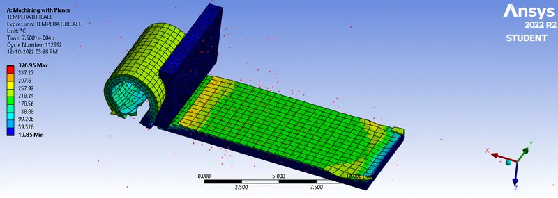
Due to the high speed cutting motion, the maximum temperature generated on the workpiece is 376.95 °C. - Animations:
- Equivalent Stress:
- Body Temperature:
- Equivalent Stress:
- Comparison:
The observations from the parametric study are as below: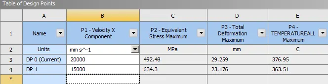
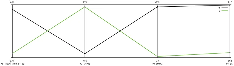
The comparison chart above shows that the stress in Case 2 is greater when the velocity is 15000 mm/s. When the velocity is low, the material can withstand more load and the stress is larger. The stress developed is way higher than the ultimate breaking strength, which is why cutting process takes place. However, the plastic strain and deformations are greater in Case 1, owing to the high velocity of up to 20000 mm/s. Also, the temperature in Case 1 is higher because the velocity in Case 1 is 20000 mm/s, so with the speed, the tool will face more material cutting in a shorter period of time, so the heating will be greater due to greater interaction between tool and workpiece, so the temperature will be higher in Case 1.
According to the results, high stresses will be generated during planer machining in the chip formation zone, secondary deformation zone, and on the machined surfaces. The sheer angle of the cutting tool influences the stress intensity and chip formation behaviour. Excessive temperature rise during the machining process occurs when the velocity of the cutting tool is low and stress is high, which can result in cutting tool failure or tool wear. The best cutting tool velocity can be determined by analysing different cutting tool velocity and reducing stress generation on the workpiece. Optimized layer of cutting surface, shear angle of tool, and velocity are critical characteristics for achieving a clean machined surface and good chip formation throughout the machining process.
Conclusion:
With Ansys Workbench, a simulation of a mechanism of Machining with Planar was conducted for different cutting tool velocity cases. According to the analysis, for both the cutting tool velocity, the developed stress is greater than ultimate stress. Thus the cutting action takes place for both the cases. Higher the velocity of the cutting tool, lower will be stress developed on the tool which means lower effort required for higher cutting speed.