ANSYS Project: Slider Crank Mechanism
Aim:
To perform a transient structural analysis of the Slider Crank Mechanism with contact and without contact between the components of mechanism and of different component materials.
Theory:
The four-bar link mechanism known as the slider-crank mechanism is used in several types of engines, pumps, and other technical mechanisms. One of the key mechanisms in machine dynamics is this one. A slider crank mechanism converts rotational motion into linear motion as its primary function. A freely moveable joint is used to link the connection rod to the crank, and the joint moves as a result as soon as the wheel begins to turn. A slider-crank linkage is a four-link device that has one sliding joint, three revolute joints, and three prismatic joints. The expansion of gases against a sliding piston in a cylinder or the rotation of the crank can both cause the linear movement of the slider.
When the connecting rod, or coupler, of a slider-crank linkage becomes the ground link, the slider is directly attached to the crank, resulting in slider-crank chain inversion. This inverted slider-crank is a type of slider-crank linkage that is frequently used to open and close swinging gates and doors as well as operate hinged joints in construction equipment like a backhoe or crane.
Following are various mechanisms using various slider crank chain links:
- First Inversion: When link 1 (the ground body) is fixed, this inversion is obtained. Applications include reciprocating compressors and engines.
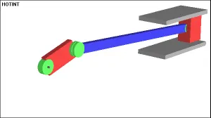
Figure: Slidercrank animation from Wikipedia - Second Inversion: When link 2 (the crank) is fixed, this inversion is obtained. Applications include Rotary engines and the Whitworth rapid return mechanism.
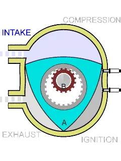
Figure: Rotary Engine - Third Inversion: When link 3 (the connecting rod) is fixed, this inversion is obtained. Applications include oscillatory engines and slotted crank mechanisms.
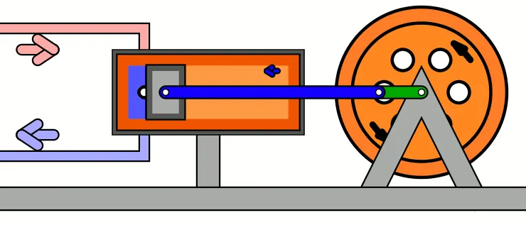
Figure: Single Acting Oscillating cylinder steam engine From Wikimedia Commons, the free media repository - Fourth Inversion: When link 4 (the slider) is fixed, this inversion is obtained. Application: Pendulum pumps, hand pumps, Bull engines, etc.
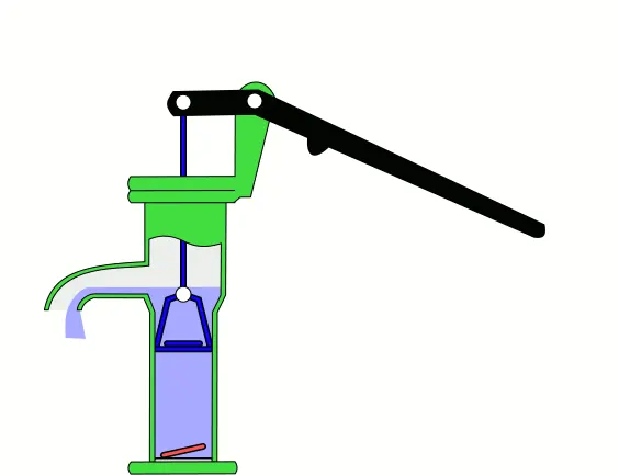
Figure: Hand Pump – Animation From Wikimedia Commons, the free media repository
In this study, the first inversion is considered where further analysis is done. The various parts of the considered Slider Crank Mechanism is labelled with the corresponding naming as per the simulation file. For the case where the contact is established, multiple materials were used for the different components.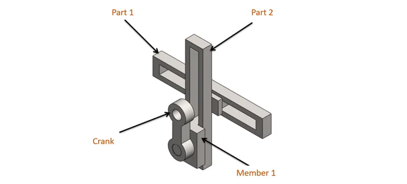
Objectives:
- Getting ready with the Slider Crank 3D models developed in Solidworks and importing it into the Ansys Workbench for transient structural Analysis.
- Application of the Boundary Conditions by setting up the contacts and joints. Also editing the analysis setting for the simulation to take place step by step.
- Determination of Equivalent Stress, Total Deformation and Total velocity of the Crank for the performed simulation.
- Repeating the simulation for other cases with contacts and friciton between components
- Analysing and Comparing the results.
Analysis Setup:
A transient structural analysis is to be conducted for a Slider Crank mechanism for two different cases: with contact established between the components and without contact established between the components. The simulation is aimed at finding the total deformation, equivalent stress and total velocity generated by crank.
- Geometry:
The 3D assembly model of the Slider Crank mechanism developed in SOLIDWORKS is shown in figure below: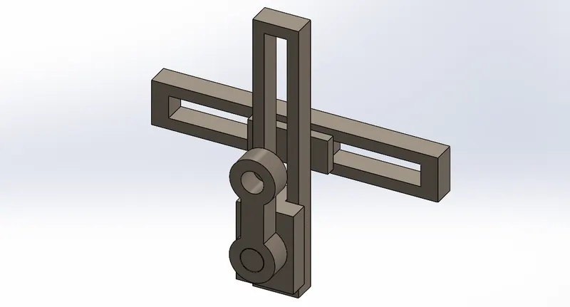
These models are then imported to Ansys Mechanical transient Structural Workbench for the analysis. - Material Properties:
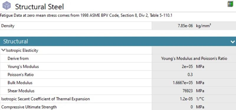
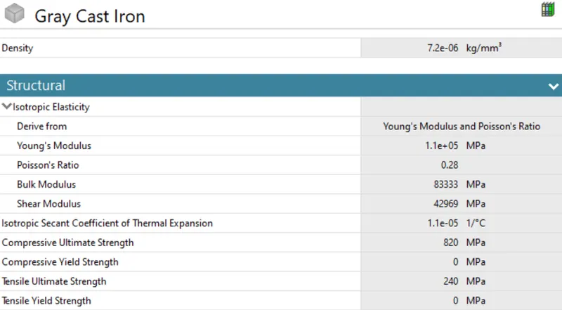
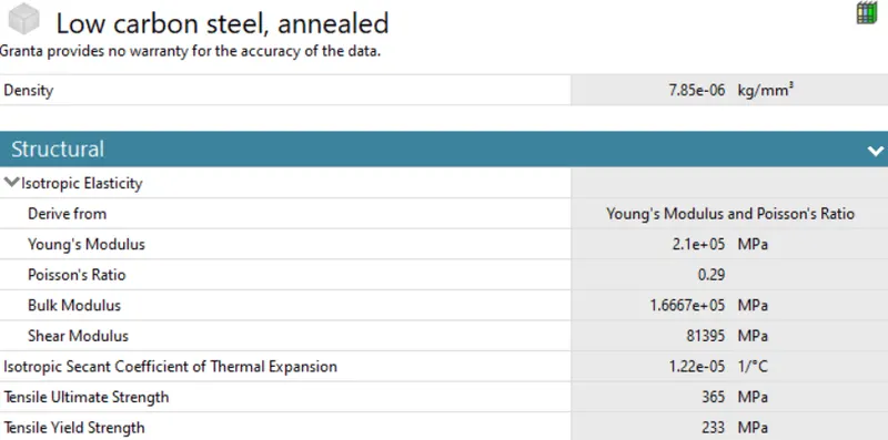
The material of Crank is set to be structural steel for both the analysis cases. For the Case 1, all the components are considered as structural steel, while for the second case, two additional materials were also considered. The Handle 2 and Fixture are considered to be Grey Cast Iron while the Handle 1 was assigned with low carbon steel. The material properties are given below:
- Structural Steel:
- Grey Cast Iron:
- Low Carbon Steel:
- Structural Steel:
- Connection Details:
The contact details were different for each Case. For the first case, there were no contacts provided. The motion was simulated just with Joints provided. For Case 2, contacts were introduced in addition to Joints similar to Case 1.
- Contact Details:
Below provides the information of the contacts introduced in each simulation Case.
- Case 1:
No Contacts between the components of Slider Crank Mechanism was introduced. - Case 2:
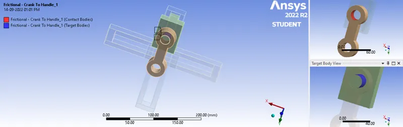
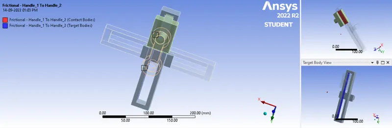
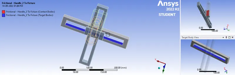
Frictional contact between mechanism components were established. The frictional coefficient between Crank and Part 1 is assigned with a value of 0.3 , and between part 1 and part with a value of 0.23. The frictional coefficient set up between part 2 and fixture is 0.15.
- Frictional Contact between Crank and Handle 1:
- Frictional Contact between Handle 1 and Handle 2:
- Frictional Contact between Handle 2 and Fixture:
- Frictional Contact between Crank and Handle 1:
- Case 1:
- Joint Details:
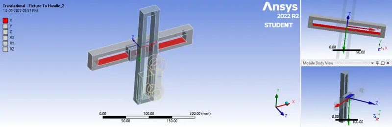
For both the cases, the Joints assigned are the same. In total, five joints were assigned: 1 fixed, 2 revolute and 2 translational. The fixed joint was established on the Fixture to restrict its motions in all directions. This is the part which is stationary. A revolute joint was assigned to the Crank and the connection type is Body to Ground to rotate the crank irrespective of any other mechanism components. Another revolute joint was assigned to Crank with connection type as body to body with Crank as mobile body and Handle 1 as reference body. A translational joint (connection type: body to body) is set up between Handle 1 and Handle 2 for the Handle 2 to move in the gap of Handle 1. Another body to body type translational joint was between fixture and handle 2 to simulate the motion of handle 2 between the gap of Fixture.
- Fixed Joint for the Fixture:
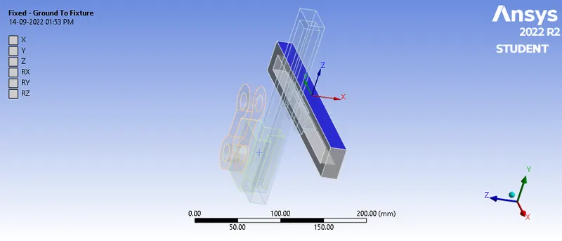
- Revolute Joint for the Crank with Ground:
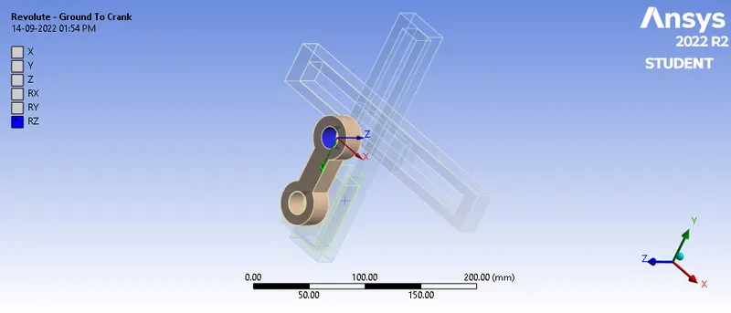
- Revolute Joint between Crank and Handle 1:
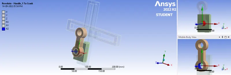
- Translational Joint between Handle 1 and Handle 2:
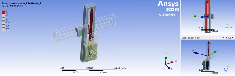
- Translational Joint between Fixture and Handle 2:
- Fixed Joint for the Fixture:
- Contact Details:
- Meshing:
The whole geomtry was meshed with an element size of 10 mm. Also, the adaptive sizing was turned off to get the mesh as required. The total number of nodes and elements generated are 17413 and 8528 respectively. The generated mesh can be seen below:

A mesh metric was used to identify elements based on their quality, and it can be observed that the elements of the lowest quality are minimum. The majority of the elements have very high quality values ranging from 0.26798 to 0.99904 with an average value of 0.78846. As a result, the mesh is of good quality. - Boundary Conditions:
The simulation was to run for 4 steps. So, the number of steps was assigned as 4. In the first step, the Large Deflection was set to 'ON' and Defined by Time. The Initial time step set to 0.2 s, Minimum time step was set to 0.1 s and the Maximum time step was set to a value of 0.3 s. In the Output Control, all output parameters were set to 'Yes'. For the steps one to four, Large Deflection was also set to 'ON' and Defined by Time. 'Carry over time' was also set to 'ON'. The Minimum time step was set to be 0.1 s and the Maximum time step was set to be 0.3 s. Here also, all the Output control parameters were set to 'Yes'.
In order to simulate the motion of the Slider Crank Mechanism, the Crank was to move 360 degrees. For that a rotational joint was set up for the analystical purpose as shown below: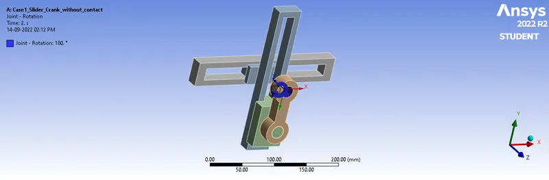

As seen from the above table, the whole 360 degrees rotation was divided between four steps in an equal manner. The co-ordinates were also edited in order to ensure the rotation of Crank along the z direction in the Connection Stage.
Results:
- Case 1: Slider Crank Model without Contacts and the material only as Structural Steel.
Following are the outputs obtained for the Case 1.
- Total Deformation:
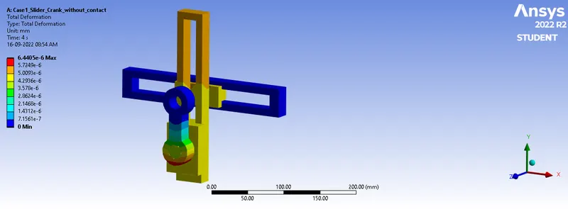
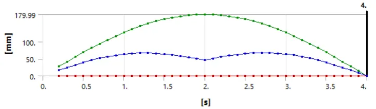
Maximum deformation over time = 179.99 mm
Maximum deformation = 6.4405e-006 mm - Equivalent Stress:
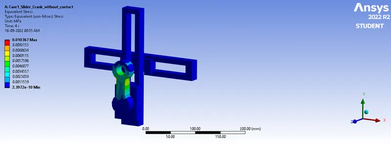
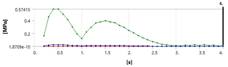
Maximum Equivalent Stress over time = 0.57415 MPa - Total velocity generated by crank:
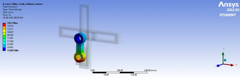
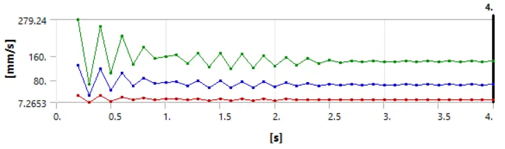
Maximum Total Velocity of the Crank = 142.2 mm/s
- Total Deformation:
- Case 2: Slider Crank Model with Contacts assigned and the materials of mechanism including Structural Steel, Grey Cast Iron and Low Carbon Steel.
Following are the outputs obtained for the Case 2.
- Total Deformation:
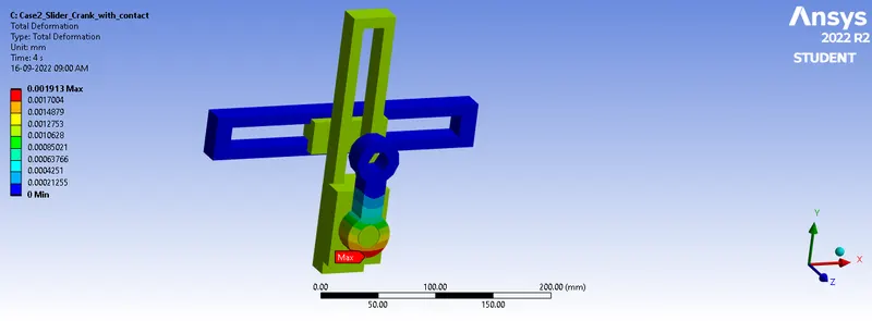
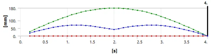
Maximum deformation over time = 180. mm
Maximum deformation = 1.913e-003 mm - Equivalent Stress:
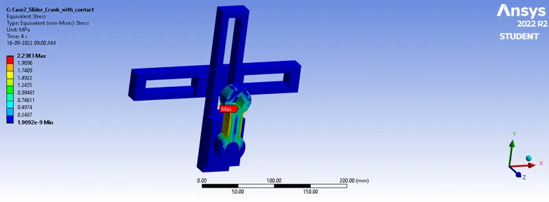
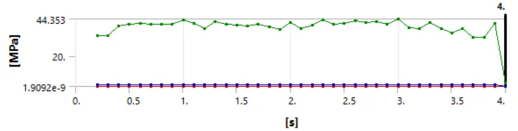
Maximum Equivalent Stress over time = 44.353 MPa - Total Velocity of the Crank:
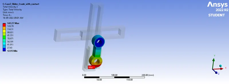
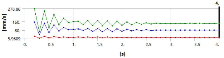
Maximum Total Velocity of the Crank = 143.27 mm/s - Frictional Stress Generated due to Friction between Various Contacts:
The following Outputs shows the frictional stress acting on each component of the mechanism. It can be seen that the maximum stress is acting on the Crank where it has the contact with the handle 1. It accounts to a value of 23.886 MPa which is very high compared to that of frictional stress developed on other components. This could be due to the fact that the coefficient of friciton is maximum between Crank and handle 1, which is 0.3. Also, rotational movement is involved, which causes stress to act on every direction.
- Frictional Stress on Crank:
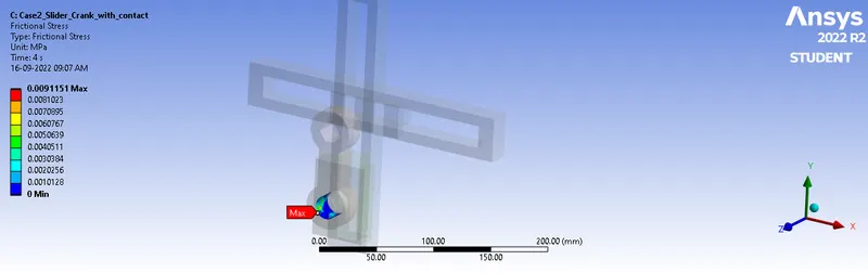
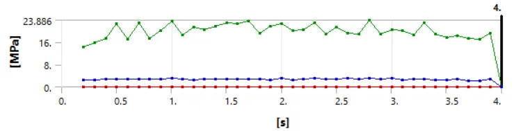
Maximum Frictional Stress over Time = 23.886 MPa - Frictional Stress on Handle 1:
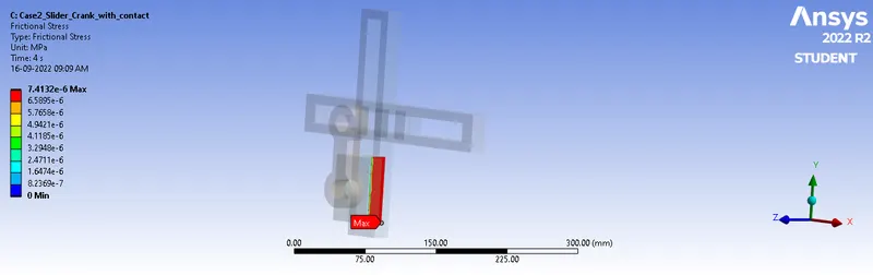
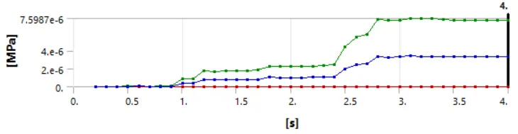
Maximum Frictional Stress over Time = 7.5987e-006 MPa - Frictional Stress on Handle 2:
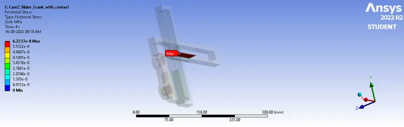
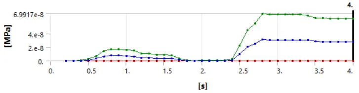
Maximum Frictional Stress over Time = 6.9917e-008 MPa
- Frictional Stress on Crank:
- Total Deformation:
- Comparison:
Case 1 Case 2 Max Total Deformation 6.4405e-006 mm 1.913e-003 mm Max Equivalent Stress 0.57415 MPa 44.353 MPa Max Total Velocity of the Crank 142.2 mm/s 143.27 mm/s
In case 2, the components' assigned contact area and coefficient of friction will impede motion, causing more stress and increased deformation as a result. Since there was no contact region in case 1, they were free to move without limitation, which led to less deformation and less stress. Case 2 seems two have higher total velocity generated by the Crank. This is due to the fact that the higher coefficient of friction is present between crank and handle 1 when compared to Case 1. Higher the coefficient of friction, higher wil be the grip between the components, therby the Crank can impart higher rotation (provided in degrees in simulation).
Also, the maximum stress developed is less than the yield limit of the materials, which means that there wont be any plastic deformation. That is, the components of the mechanism would retain its original structure and shape, which is observable from the total deformation data for both the cases that are closer to the zero value. - Animations:
- Case 1: Equivalent Stress
- Case 2: Equivalent Stress
- Case 1: Equivalent Stress
Conclusion:
Transient Structural Simulation of Slider Crank Mechanism was conducted successfully for the two different cases. The first case where there is friction between the contact and with same material, and the second case with friction between the mechanism components and multiple material for the components. From the analysis it is found that the stress is below the elastic limit, that is, no permanent deformation. The maximum stress is seen for the Case 2, which is obvious due to the presence of friction between the components. Among the components, the maximum stress is observed between the Crank and Handle 1 due to high coefficient of friction.