Simulink Project: Control Logic of a Gear Shift
Aim:
To make a Simulink chart for the gear shift logic as per various conditions.
Problem Statement:
The control logic should be as per the following Condition:
| Speed Range (kmph) | Gear |
| 0 to 15 | 1 |
| 16 to 25 | 2 |
| 26 to 40 | 3 |
| 41 to 60 | 4 |
| Above 61 | 5 |
For the given input speed while simulation is running, the gear number is to be displayed.
Theory:
A transmission is a mechanism that offers a regulated application of power in a power transmission system. The gearbox, which uses gear and gear trains to provide speed and torque conversions from a rotating power source to another device, is sometimes referred to as a 5-speed transmission. The most typical application is in automobiles, where the transmission converts the internal combustion engine's output to the driving wheel. Such engines must rotate at a relatively high rate, which is inefficient for starting, stopping, and slower movement. The transmission shifts the greater engine speed to the slower wheel speed, which increases torque. Transmissions are also utilized on pedal bicycles, stationary machines, and other applications that require varied rotational speeds and torques.
Figure 1: Transmission System [1]
Figure 1 shows an example for the transmission system consisting of multiple gears. A gearbox will usually have many gear ratios or simply gears with the ability to change between them as speed changes. The operator can switch manually or automatically with the help of a control unit. Control in either direction (forward or backward) is also possible. There are also single ratio transmissions that adjust the speed and torque (and sometimes the direction) of the motor output.
Objectives:
- Understand the theory of Transmission system.
- Develop a Simulink model for Gear Transmission with control logic.
- Analyze the model.
Simulink Model:
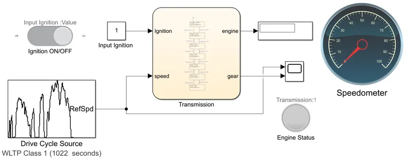
The transmission system has two inputs, Input Ignition and Drive Cycle Source. For getting the input velocity source, two which the transmission system need to change the velocity, the inbuilt Drive Cycle is chosen. WLTP Class 1 drive cycle is chosen for this particular study. The Input ignition can only have the value 1 and 0, which is controlled using the slider switch Ignition ON/OFF. Transmission chart consists of the logic control were the system choose appropriate gear for that particular velocity. The Speed Gauge is connected with the input speed, which represent the input velocity in analog form. There are two outputs from the Transmission. The output engine represents the status of the engine whether it ON or OFF. This is directly coupled with lamp Engine Status which turns green if the Ignition is ON. To compare gear for each velocity, a Scope is used which has two inputs. One is input velocity and the other is the gear chosen by the transmission for each velocity. The model is ran for 1022 seconds.
Stateflow
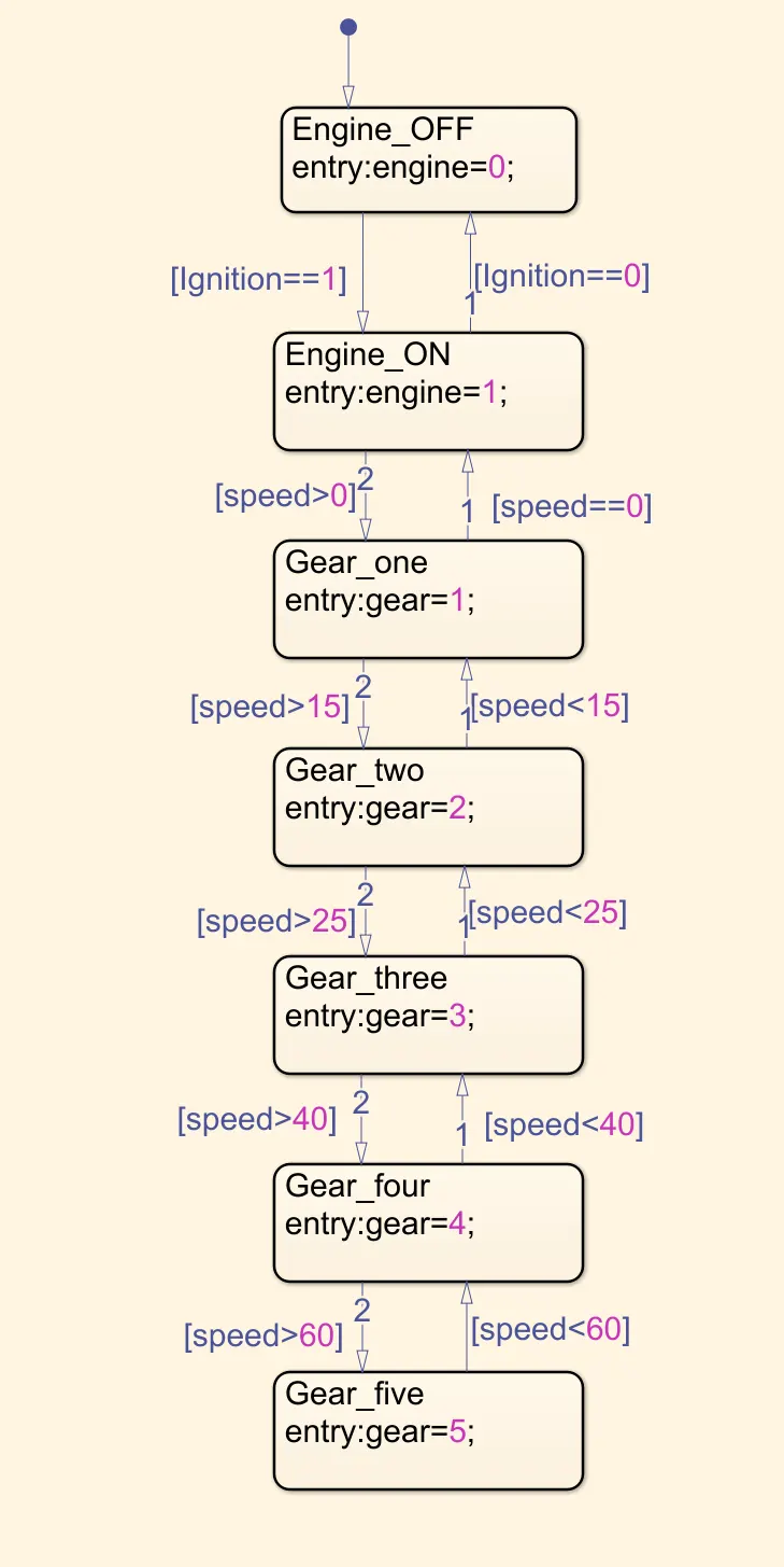
Output and Explanation of Stateflow of Gear Transmission:
The chart consist of two input data Ignition and Speed, and two output data engine and gear. The screenshot of the Symbols Pane is shown in Figure 2.
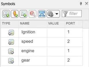
Figure 2: Symbols Pane showing the data used in chart.
The first two states Engine_OFF and Engine_ON checks if the ignition is ON or OFF, and the output date engine is given the value 0 or 1 accordingly. The lamp connected with this output data engine turns green if it has the value 1, therby indicating the Engine Status if it is ON or not. The states Gear_one, Gear_two, Gear_three, Gear_four, and Gear_five activates according to the input data speed. Gear_one activates if speed is less than 15, Gear_two when speed is between 15 and 25, and similarly for the other states as well as shown in Stateflow.
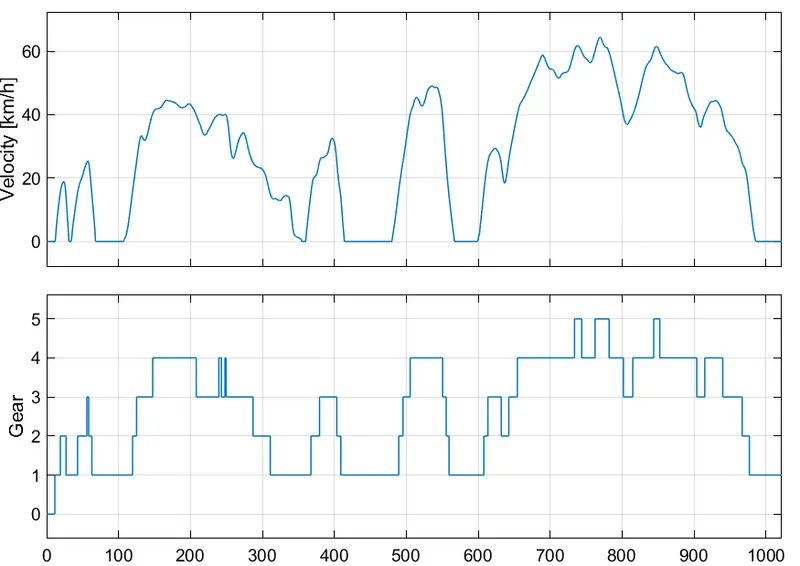
Figure 3: Input velocity and corresponding chosen gear.
The output from the scope is shown in Figure 3. It is seen that the transmission system has successfully chosen the required gear for the given input velocity.
Modified Simulink Model:
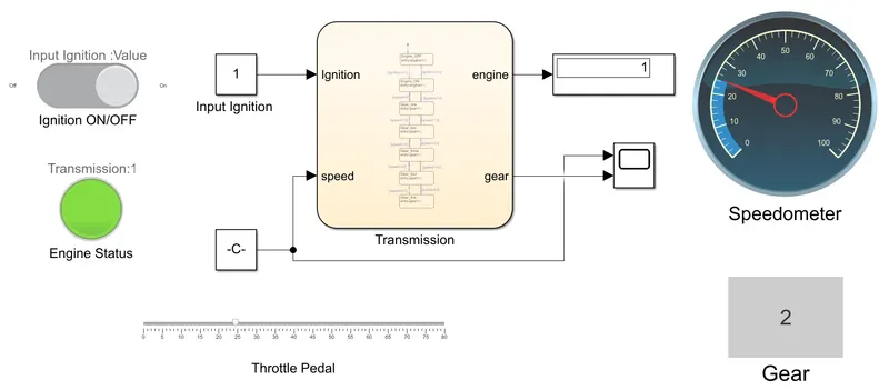
The Simulink model can be modified slightly by replacing the input drive cycle with the pedal, where the input speed can be varied in real time. Also, a display can be connected with the output gear, where it can numerically represent the current gear. The modified Simulink model is shown below. The logic control of the transmission is untouched
Simulink Model File:
To download:
Developed Model: https://drive.google.com/file/d/1-ImBSQf7BmL_HK-46p7PEYvk-SSwNAJZ/view?usp=sharing
Modified Model: https://drive.google.com/file/d/1DQtD3uZmMfYbphHkPmVlztl327XPqlzE/view?usp=sharing
Conclusion:
A Simulink chart for the Gear shift control logic is developed successfully and has been analyzed.
References:
[1] https://www.fahadhvhassan.com/manual-transmission-components-types-working-principles-and-applications%EF%BB%BF/