ANSYS Project: Long Piston With Cam
Aim:
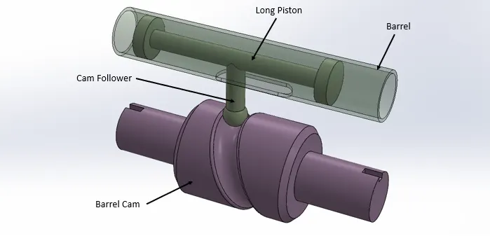
To perform a transient analysis to simulate the Long Piston Cam Model.
Theory:
The piston transmits to the crankshaft the force of the combustion and expansion of the power stroke through its connecting rod and bearing. The piston assembly is made up of the piston, its rings, and the piston or gudgeon pin. This piston's cutaway design enables it to pass through the counterweights on the rotating crankshaft. The combustion chamber's form, as well as the piston's compression ratio, determine the crown's shape. Diesel engines employ pistons with various shapes because, depending on the injection method, the combustion chamber may be completely or partially formed in the piston crown. The piston crown could be dome-shaped, flat, concave, or recessed. Significant heat and pressure must not damage the piston. Additionally, it must change directions up to hundreds of times each second, or roughly 10 times per second. The weight of the pistons is significant for engine balance in the majority of engines. For this reason, pistons ought to only be changed in matching sets. While some aluminum alloy pistons are cast, others are forged. All pistons grow in size as they warm up. The gudgeon pin area expands the greatest since there is more metal there. Many pistons are machined into a somewhat oval form to accommodate this. It's known as cam grinding. The piston then turns round as it expands and heats up.
A mechanical tool called a cam is used to directly convey motion to a follower. The member being driven is referred to as the follower, and the driver is known as the Cam. A Cam-Follower combination typically has a rotating Cam and a translating or oscillating Follower. The crankshaft of a car engine is a well-known example, where the cams drive the push rods, which act as followers to open and close the valves in time with the motion of the pistons. For a design engineer, creating a cam is a challenging and demanding task because every rival in the market is constantly seeking improved mechanical system performance. A design engineer must therefore seek out an objective mechanism. Additionally, it's critical to search for improved performance under actual loading circumstances. With the aid of transient structural analysis, it has made possible to understand how a mechanism behaves and how deformation, stress, and strain all change over time.
Objectives:
- Getting ready with the Long Piston With Cam 3D models developed in Solidworks and importing it into the Ansys Workbench for Transient Analysis.
- Apply Boundary Conditions by setting up the contacts and joints. Also editing the analysis setting for the simulation to take place step by step.
- Determine Directional Deformation, Equivalent Stress and Equivalent Elastic Strain results for the performed simulation.
- Conducting the parametric study for other frictional coefficients.
- Analyzing the result and developing an inference for the trend shown with frictional coefficient value.
Analysis Setup:
A static structural analysis is to be conducted for the Long Piston With Cam setup for different coefficient of friction . The material of Long Piston, Barrel, Cam Follower and Barel Cam is kept same for all the cases.
- Geometry:
The 3D assembly model of the Long Piston With Cam mechanism developed in SOLIDWORKS is shown in figure below: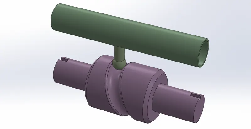
These models are then imported to Ansys Mechanical Transient Structural Workbench for the analysis. - Material Properties:
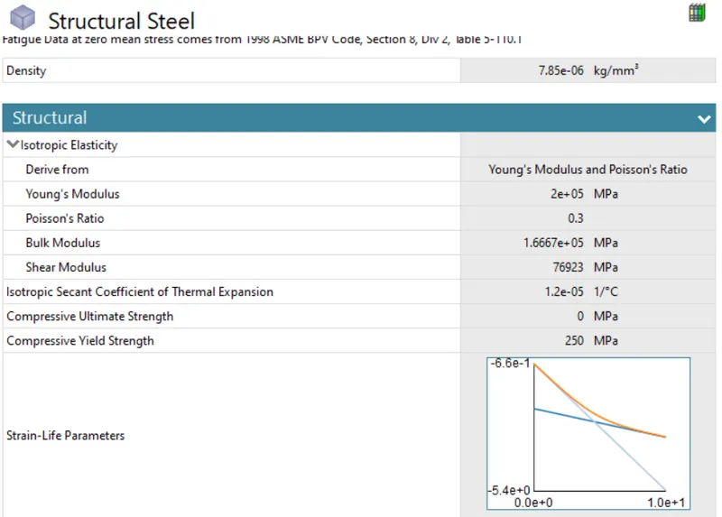
The material of complete model is set to be structural steel for all the analysis. The material properties are given below:
- Structural Steel:
- Structural Steel:
- Contact Details:
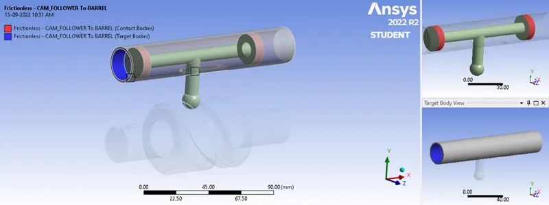
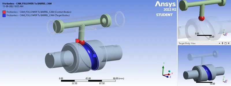
Two contacts created in the whole setup. First contact is between Cam Follower and Barrel Cam. The second contact is between Long Piston and Barrel. For each cases, the frictional coefficient value is changed. For the first case, it is considered to be frictionless which means frictional coefficient equals zero. For the second and third cases, the frictional coefficient is considered to be 0.1 and 0.2. A parametric study can be done to compare each cases with different frictional coefficient values. The interface treatment is set to Add offset, Ramped effects for the analysis.
- Contact between Long Piston and Barrel:
- Contact between Cam Follower and Barrel Cam:
- Joint Details:
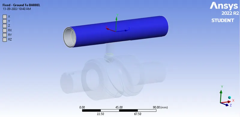
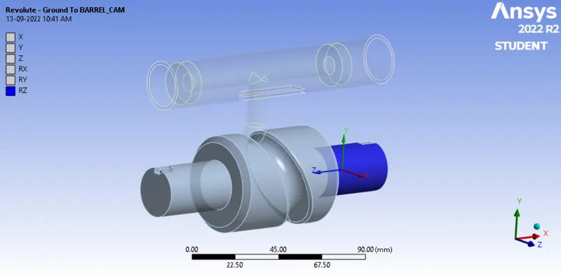
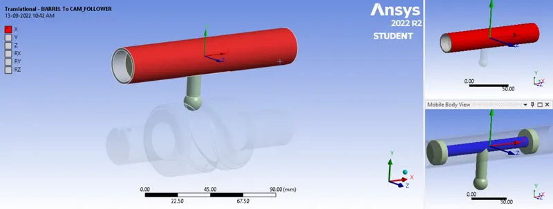
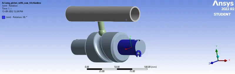
A revolution joint has been assigned to the Barrel Cam to replicate the rotational motion of Barrel about Z axis. A fixed joint is assigned to the Barrel to restrict its motion as it is fixed. A translational Joint is provided to the Piston as body to body as Barrel as body to replicate the to and fro motion of the Piston.
- Fixed Joint for the Barrel:
- Revolute Joint for the Barrel Cam:
- Translational Joint for the Piston:
- Fixed Joint for the Barrel:
- Contact between Long Piston and Barrel:
- Meshing:
Along with default meshing, an additional face sizing is provided. This would help in capturing the result accurately between the contact region of cam follower & Barrel cam. The refinement of the mesh using Face sizing is done with the element size of 3 mm. Also, "No" option is selected for Adapative sizing. The total number of nodes and elements generated are 2901 and 1082 respectively. The generated mesh can be seen below: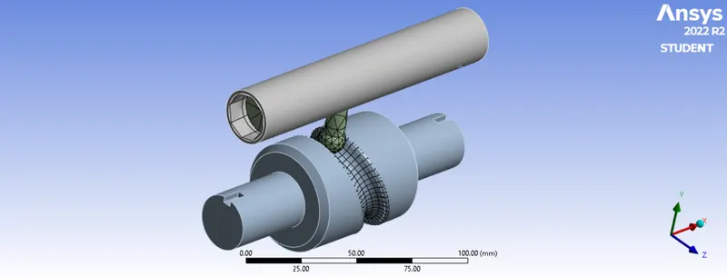
Mesh are not generated on the Barrel Cam and Barrel except for the contact region because of the fact that they are considered as a rigid body. This is done to concentrate the study on Piston and Cam Follower where the stress and deformation are more like to happen.
A mesh metric was used to identify elements based on their quality, and it can be observed that the elements of the lowest quality are minimum. The majority of the elements have very high quality values ranging from 0.20949 to 0.99963 with an average value of 0.90472. As a result, the mesh is of good quality. - Boundary Conditions:
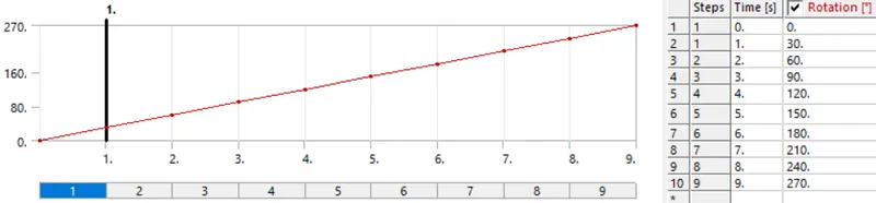
The total number of steps for analysis is specified as 9. For step 1, auto time stepping is set to ‘On’ with the minimum and maximum time step being specified as 0.05 s and 0.2 s respectively, with an initial time step of 0.1 s. For step 2 to 9 auto time stepping is set to ‘On’ with the minimum and maximum time step being specified as 0.05 s and 0.3 s with an intial time step of 0.1 s. For all the steps, under solver control, the large deflection is set to ‘On’ and solver type is selected as ‘Program Controlled’. For the Weak Spring option, it is set to be 'Program Controlled'. Energy dissipation ratio is set to be 0.1 and the all the output controls are set to ‘Yes’.
- A Rotational Joint is set for the Barrel Cam ranging from 0 to 270 degrees. This would force the cam follower to move along x-axis only as the motion along other directions are restricted by the Barrel. The rotation joint provided can be seen below:
- A Rotational Joint is set for the Barrel Cam ranging from 0 to 270 degrees. This would force the cam follower to move along x-axis only as the motion along other directions are restricted by the Barrel. The rotation joint provided can be seen below:
Results:
In order to accomodate the comparison of different cases with different frictional coefficient, a parametric study was done which compares the maximum Directional Deformation, Maximum Equivalent Stress and Maximum Equivalent Strain.
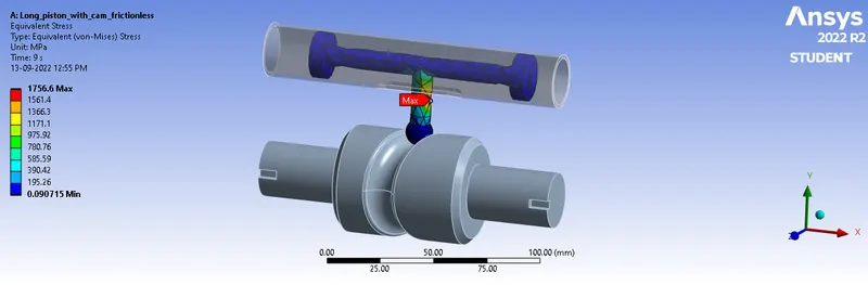
Below provides the observation for the case 1 where the contacts are frictionless.
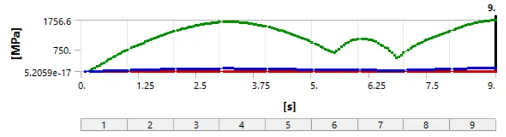
- Equivalent Stress:
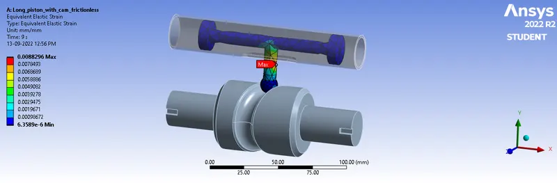
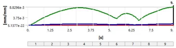
- Equivalent Elastic Strain:
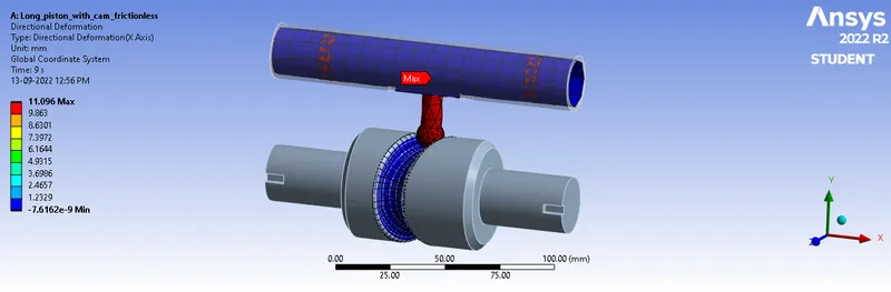
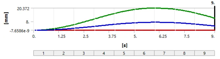
- Directional Deformation:
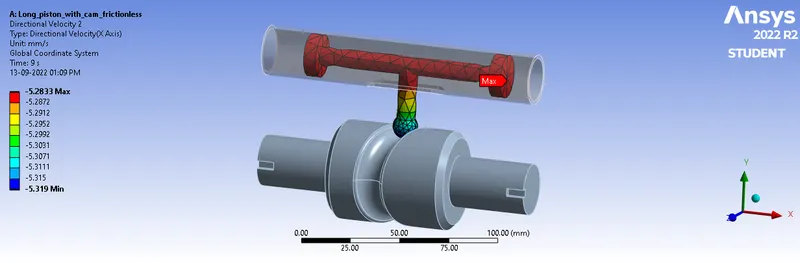
- Directional Velocity:
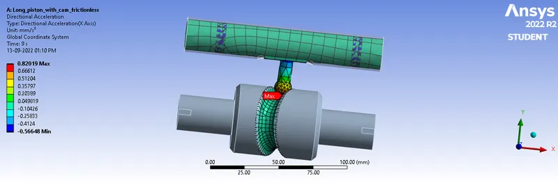
- Directional Acceleration:
- Animations:
- Equivalent Stress:
- Equivalent Elastic Strain:
- Directional Deformation:
- Equivalent Stress:
- Comparison:
The observation from the parametric study is as below: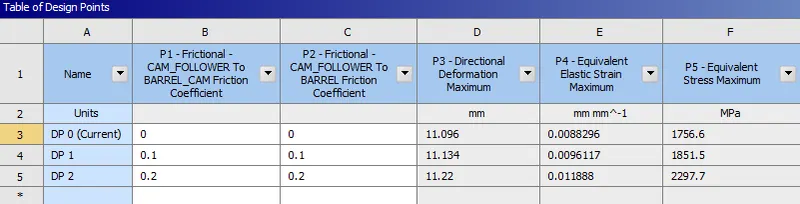
As observed in the preceding table, all cases exhibit about the same degree of directional deformation with a value of 10.5 mm. With rising frictional coefficient values, there is a minor increase in the value of directional deformation.
With a frictional coefficient of 0.2, frictional contact has the highest equivalent stress. The measurement is 2297.7 MPa. With a value of 1756.6 MPa, the value achieved for frictionless contact is the lowest.
Similar to the deformation and Stress, the frictional contact with a frictional coefficient of 0.2 exhibits the largest corresponding elastic strain. The result is 0.01188 as the value. The value of 0.0088296 for frictionless contact is the minimum.
Since perfect friction-free contact between the cam and follower is never feasible. So any system should have a minimum amount of friction should be preferred. The results show that the deformation caused by higher pressure also increases as friction increases, as do the values of stress and strain. Higher friction causes pressure to deform at the follower's tip, where it comes into contact with the cam. Due to the cam's following path, it may bend or twist. Because rotational motion is transferred to translational motion through the cam and follower, friction coefficient is crucial. Also, the following path is also very important. In barrel kind of cam, there can be the number of revolutions that are to be followed by the Cam follower. By reducing friction, it is possible to produce better results in terms of appropriate transmission and extend the lifespan of the mechanism.
Conclusion:
The long-piston-cam transient structural analysis is completed successfully.
The three simulation cases' findings are effectively found. Because friction is the force that prevents relative motion between two contacting surfaces from occurring, it develops more deformation when the coefficient of friction is higher. As a result, the equivalent stress and equivalent elastic strain in the analysis increases with the friction between the contacts.