Assignment 5-RADIOSS Interfaces & Study of Effect of Notches Challenge
AIM:
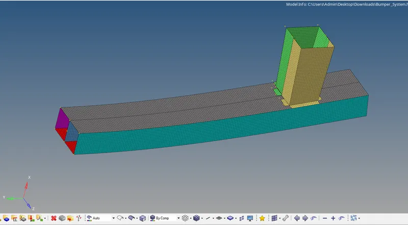
- Create a bumper assembly mesh, mesh size should be 6mm.
- Launch the Crash tube model in 6 different cases as given below and compare.
Purpose:
- Launch the crash tube model as it is.
- Change Inactive = 6 and apply.
- Create a type 11 contact and use
- Remove both notches and remove the boundary condition from the solid body node and activate.
- Create a new notch in the middle, select the entire category, and apply.
- Create a new notch with only nodes from 2 opposing faces and run.
PROCEDURE:
Mesh the given bumper model.
STEP 1. Import the given model using the IMPORT MODEL option from Hypermesh.
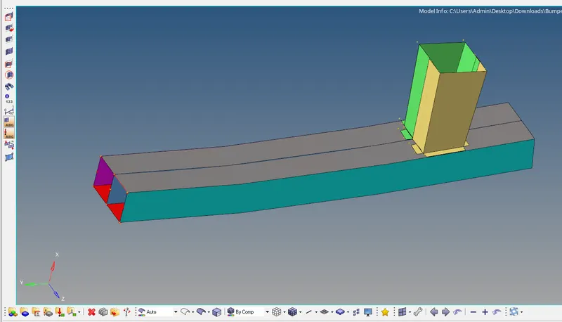
STEP 2
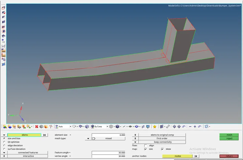
After cleaning the geometry next is to mesh the bumper surface. To achieve this, use the 2D >>> auto mesh or F12 button. Give mesh 6 mm.
iven model using IMPORT MODEL option from Hypermesh.
Case 1
- In this case, we need to use the simulation in the crushing tube as it is. we will be discussing the type of 7 interfaces where the inacti is set to 0 (Default).
- Go to import>>> import solver deck>>> select Crash_tube_0000.rad>>> import.
- Go to View>>> select browsers>>> then select hypermesh>>> select solutions.
- Right-click on the server tab>>> create>>> select TH>>> click on PART>>> select all items.
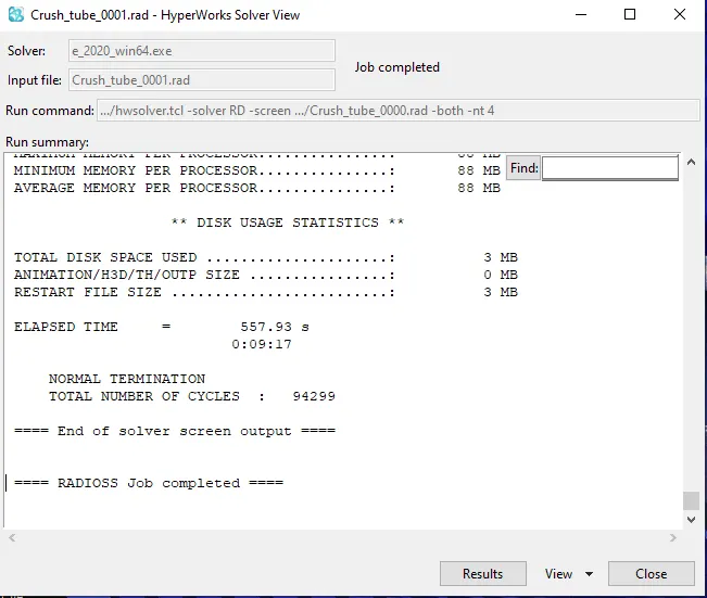
- Go to analysis>>> Click on RADIOSS> check: enter connectors>>> Change options into: -nt 4> click Radioss.
CASE 2
- Go to import>>> import solver deck>>> select Crash_tube_0000.rad> import.
- Go to View>>> select browsers> then select hypermesh>>> select solutions.
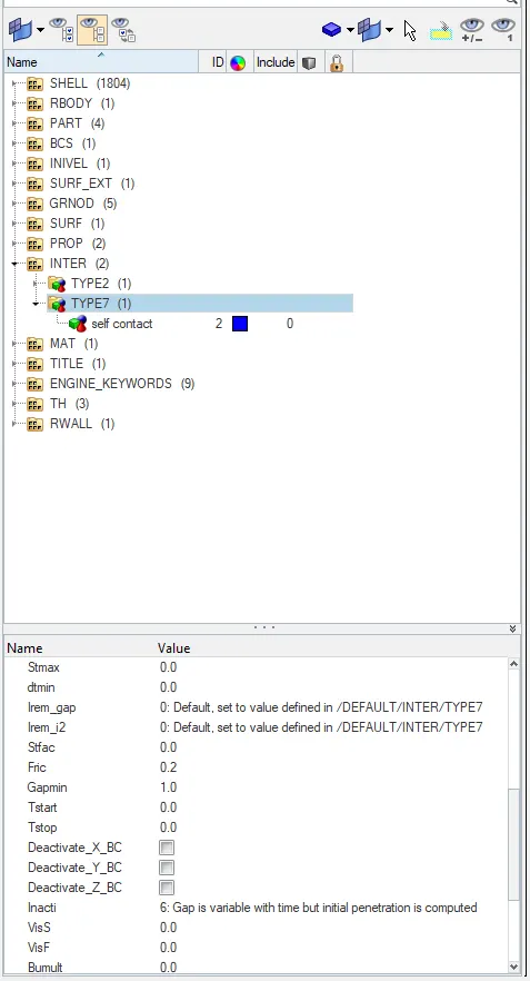
- Now in solvers>>> select INTER>>> under type 7 change Inacti to 6.
- Right-click on the server tab> create>>> select TH>>> click on PART>>> select all items.
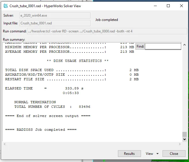
- Go to analysis>>> Click on RADIOSS>>> check: install connectors>>> Change options into: -nt 4>>> click Radioss
CASE 3
- Go to import>>> import solver deck>>> select Crash_tube_0000.rad>>> import.
- Go to View>>> select browsers>>> then select hypermesh>>> select solutions.
- Now in solvers>>> select INTER>>> under type 7 change Inacti to 6.
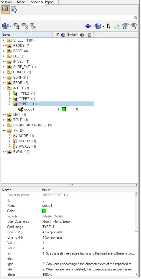
- In solvers>>> right click>>> create>>> select INTER>>> Then select type 11. Set type 11 properties given in the image below.
- Right-click on the server tab>>> create>>> select TH>>> click on PART>>> select all items.
- Go to analysis>>> Click on RADIOSS>>> check: enter connectors> Change options into: -nt 4>>> click Radioss.
CASE 4: Remove both notches and remove boundary condition on rigid body node then run.
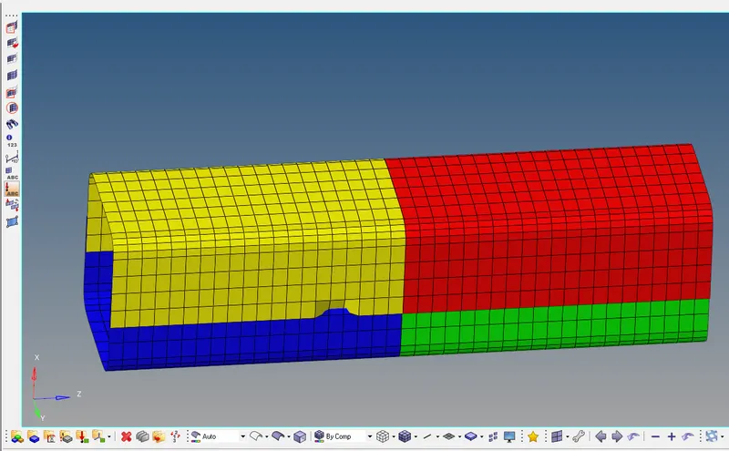
Import the 0000.rad file. Then remove the notch in the model using Align option. select reference nodes as 1st node and 2nd node. after that select the nodes that need to be aligned. now select the alien import MODEL option from Hypermesh.
- Go to import >>> import solver deck >>> select Crash_tube_0000.rad >>> import.
- Go to view >>> select browsers > then select hypermesh >>> select solvers.
- Now in solvers >>> select INTER >>> under type 7 change Inactive to 6.
- In solvers >>> right-click >>> create >>> select INTER >>> Then select type 11. Set the properties of type 11 given in the picture above.
- Go to solvers >>> right-click BCS >>> delete.
- Right-click in solver tab >>> create >>> select TH >>> click on PART >>> select all the components.
- Go to geometry >>> node edit > select align nodes >>> remove the notch using this tool.
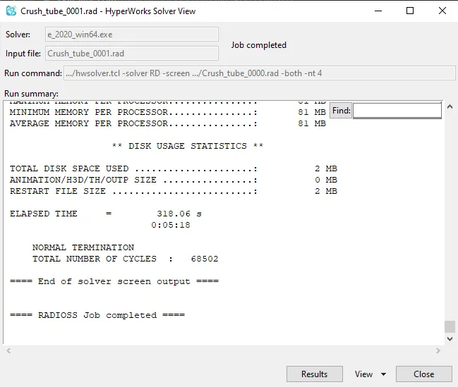
- Go to analysis >>> Click on RADIOSS >>> check : include connectors > Change options to : -nt 4 >>> click Radioss.
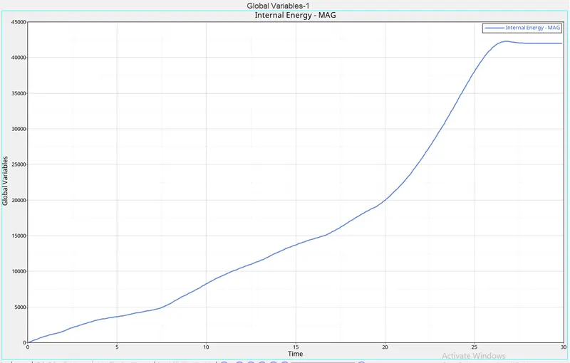
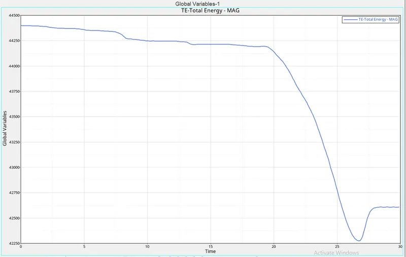
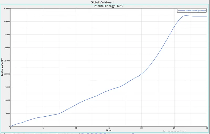
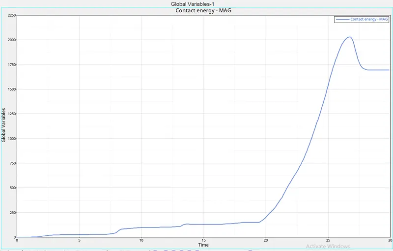
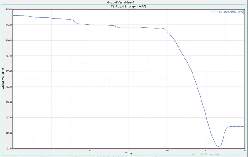
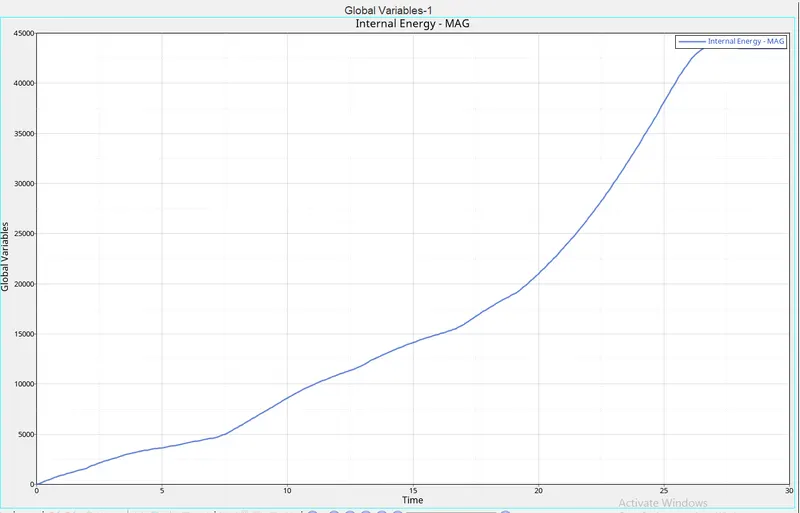
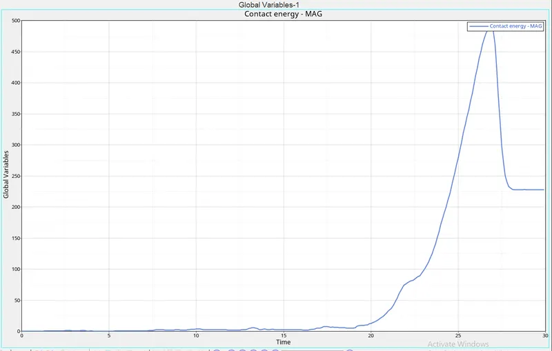
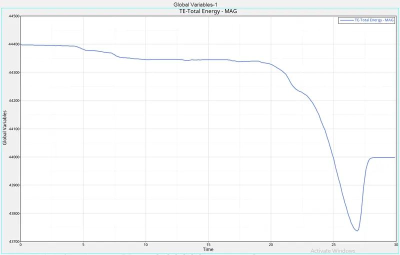
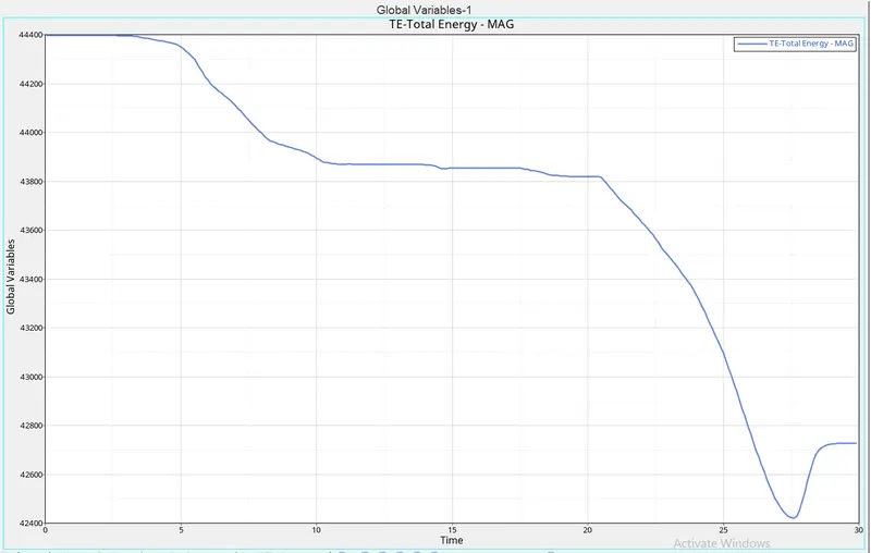
Here we can switch to hypergraph 2D panel for plotting graph via client selector. In this panel, we need to load the T01 file in the file directory. Now select variables as Internal Energy, Kinetic Energy, total energy, contact energy, hourglass energy, and select parameter as MAG and apply for plotting the graph.
alien import MODEL option from Hypermesh.
CASE 5
In this case, we will be using the starter file of case 4. Therefore, there are no notes or conditional parameters. But this case requires that we build a note with the middle section of the crushing tube. For this, I have used the translation tool in Hypermesh. Go to tools> translate.
We can select the elements or nodes to translate. After providing a translation indication (using an axis or vector), then we need to assign a size. Depending on the world's axis, then we have to click 'translate +' or 'translate-'. This creates stress
- Go to import >>> import solver deck >>> select Crash_tube_0000.rad >>> import.
- Go to view >>> select browsers >>> then select hypermesh >>> select solvers.
- Now in solvers >>> select INTER >>> under type 7 change Inactive to 6.
- In solvers >>> right-click >>> create >>> select INTER > Then select type 11. Set the properties of type 11 given in the picture above.
- Go to solvers >>> right-click BCS >>> delete.
- Right-click in solver tab >>> create >>> select TH >>> click on PART >>> select all the components.
- Go to geometry >>> node edit >>> select align nodes >>> remove the notch using this tool. And use the same tool to create the new notch in the middle.
- Go to analysis >>> Click on RADIOSS >>> check : include connectors >>> Change options to : -nt 4 >>> click Radioss.
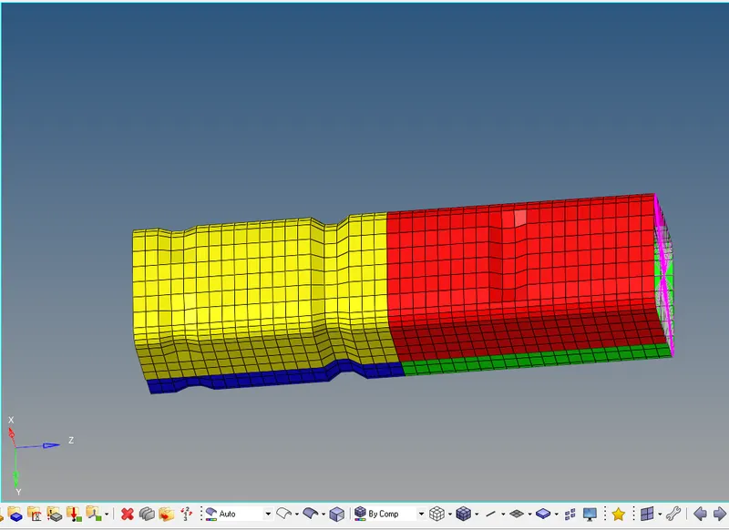
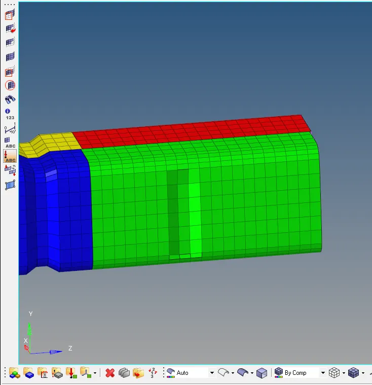
For this case, we shall be using the starter file of case 4. So, there are no notches or boundary conditions. But the case requires us to create a notch through the middle section of the crush tube. For this, I have used the translate tool in Hypermesh. Go to tools > translate.
We can either select elements or nodes to translate. After assigning the direction of translation (using an axis or a vector), we then need to assign a magnitude. Depending on the global axis, we then must either click 'translate+' or 'translate-'. This creates the depressiontion from Hypermesh.
CASE 6
Go to import>>> import solver deck>>> select Crash_tube_0000.rad>>> import.
Go to View>>> select browsers>>> then select hypermesh>>> select solutions.
Now in solvers>>> select INTER>>> under type 7 change Inactive to 6.
In solvers>>> right-click>>> create> select INTER>>> Then select type 11. Set type 11 properties given in the image above.
Go to solvers>>> right-click on BCS>>> delete.
Right-click on the server tab>>> create>>> select TH>>> click on PART>>> select all items.
Go to geometry>>> edit node>>> select sync locations>>> delete notch using this tool; use the same tool to create new notes depending on the given situation.
Go to analysis>>> Click on RADIOSS>>> check: enter connectors>>> Change options into: -nt 4>>> click Radioss.
CONCLUSION:
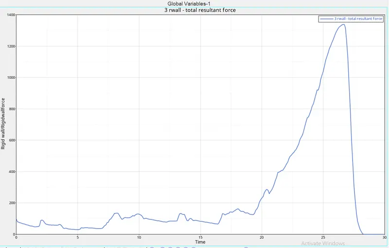
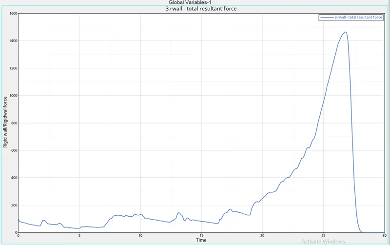
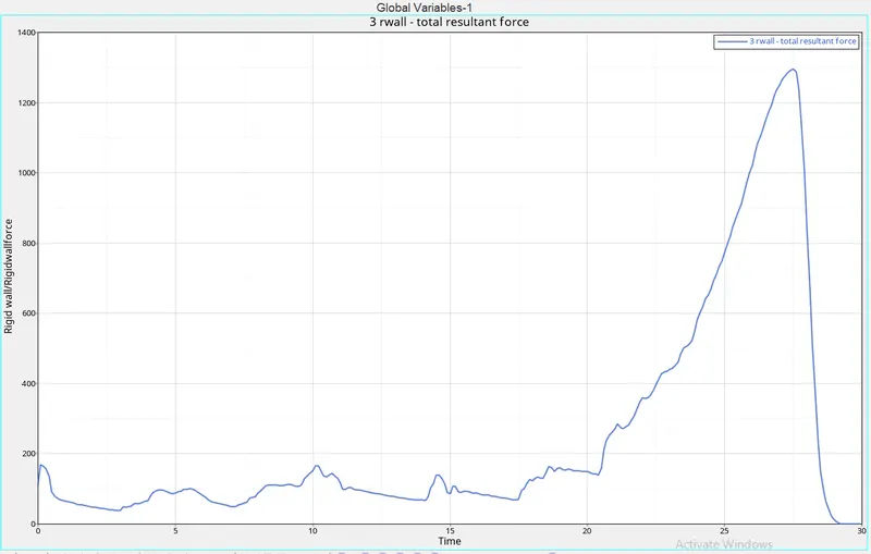
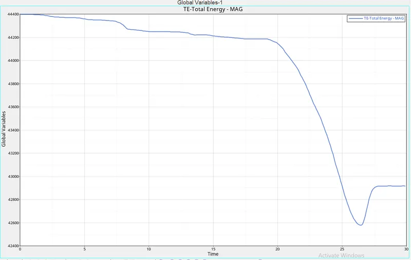
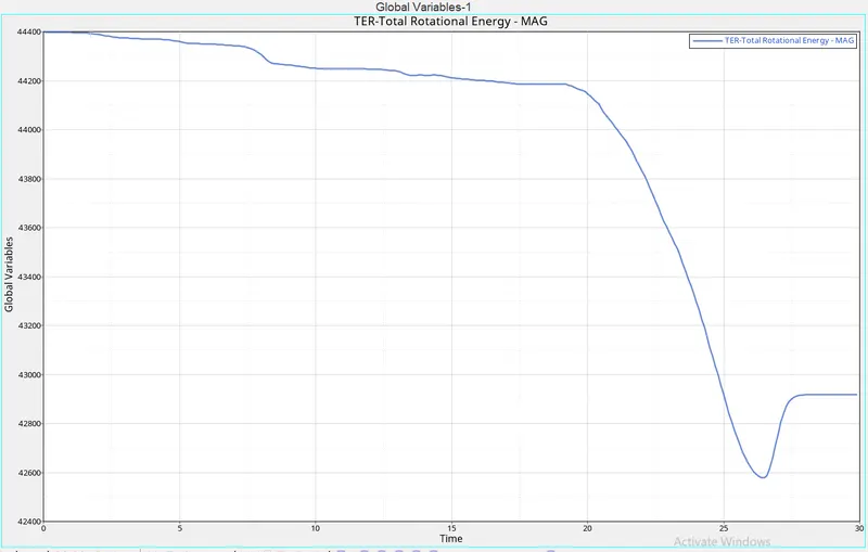
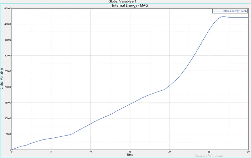
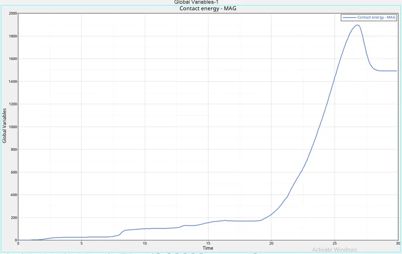
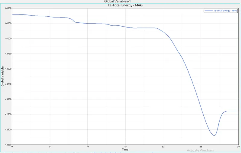
To reap the plots we use a hyper-graph. change the application to hypergraph and then import the T01 file to attain the outcomes for each of the cases. The results acquired using hyper-graph are internal energies, touch energies, overall resultant forces, and component internal energies contrast between all of the instances.
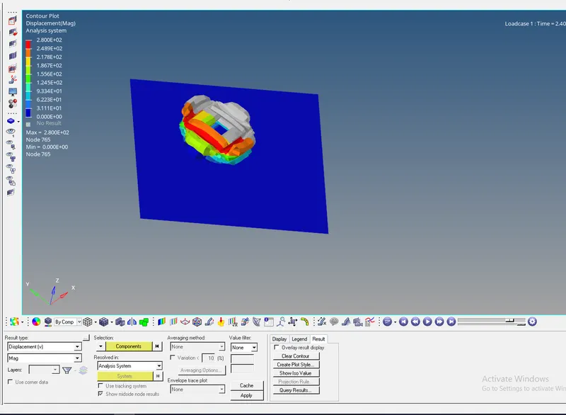
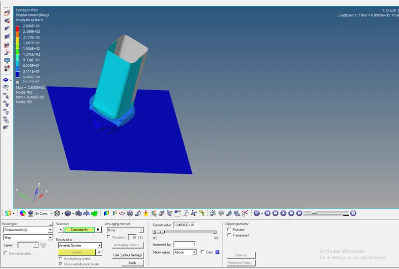
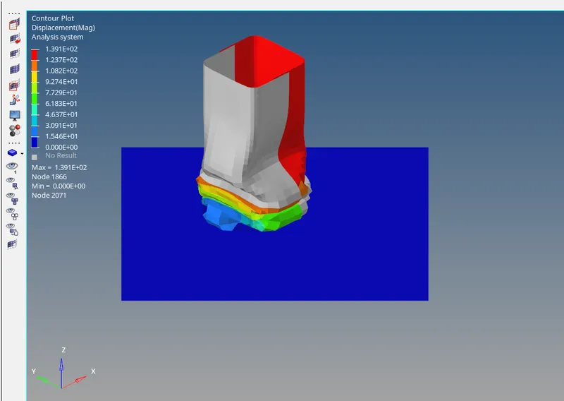
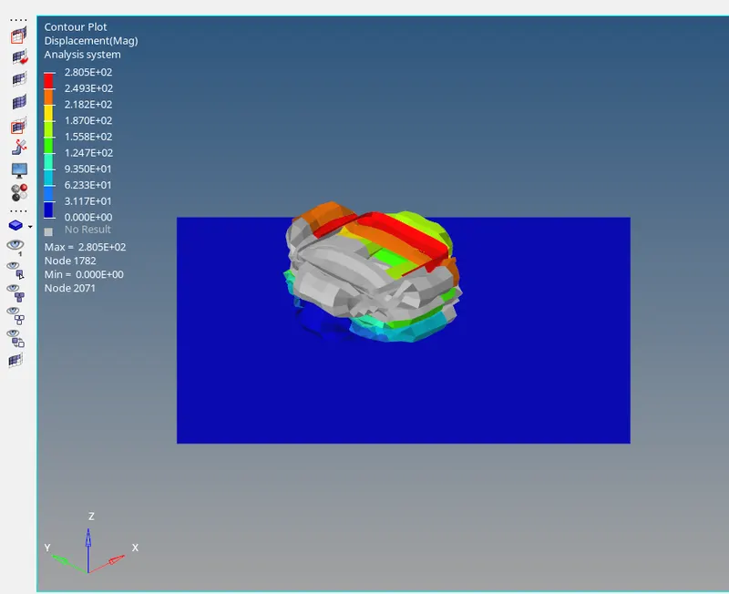
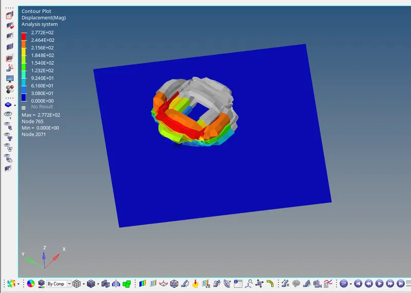
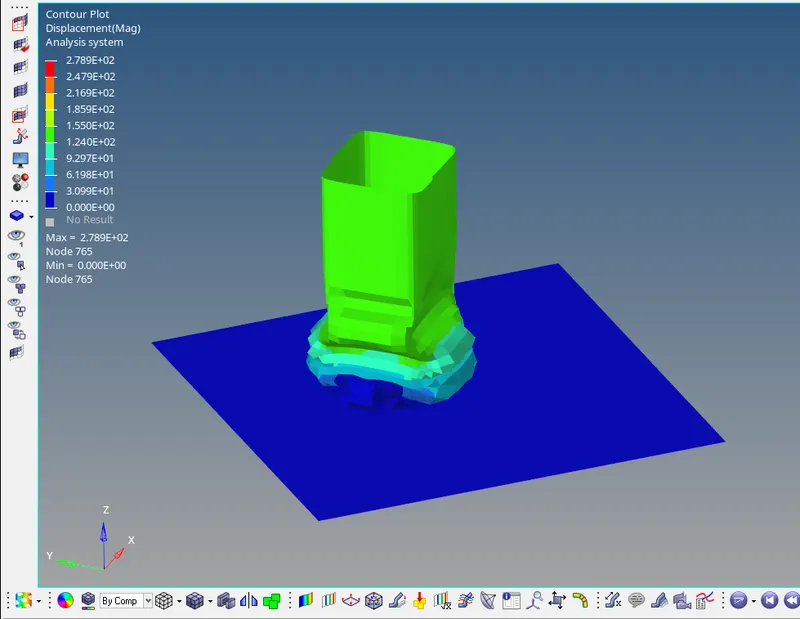
On the side of that, we examine animations too. that are achieved using Hyper-view. alternate the software to hyper-view after which import the h3d record. change the parameter to von misses/contact forces [depending on the property to be analyzed] then pick all the components and use the simple approach to animations for all of the instances.
1. Internal energy:
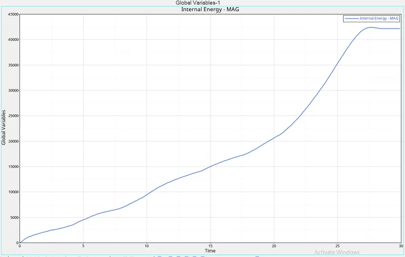
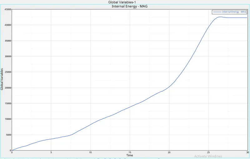
Internal energies altogether the cases are sen to extend exponentially to a maximum value then decreases. This maximum increase is seen between 25 - 27.5 ms. the utmost value of internal energy among all the cases is just in case 1 which is to a worth of 42500. Here, cases 2 and three have equivalent values of internal energies in the least times. within the 4th case where there are not any notches, initially, the interior is seen to be maximum then its rate of increase decreases compared to cases 5 and 6. Its value between 7 to fifteen ms is seen to be equivalent to that of cases 1,2,3&5 however the utmost value of internal energy is slightly but cases 1,2,3. Comparing cases 5 and 6, we observe that case 6 is seen to possess the utmost internal energy most of the time but its maximum value is a smaller amount than case 5. Comparing cases 4, 5 & 6 we see that absence of condition and increase within the notches decrease the utmost value of internal energy but these cases have greater values of internal energies in the least times, but, the utmost.
2. Contact Energy:
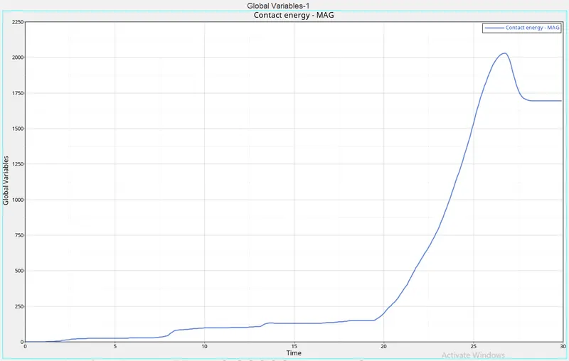
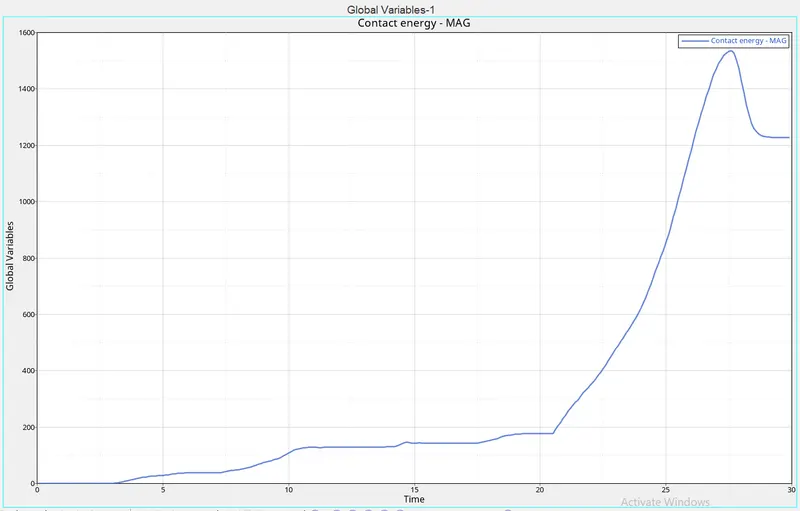
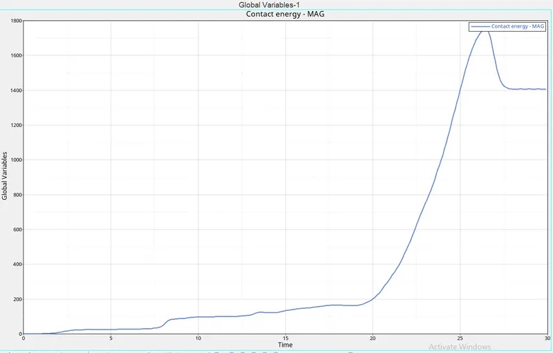
the speed of increase within the contact energy with time is exponential at the start, then the rise is seen to be a mixture of linear and exponential for a quick period followed by a rapid exponential increment till it reaches its peak then it drops and becomes constant. the height is seen to vary as compared to the interior energies. Here case 6 has the utmost value of the contact energy followed by case 5, then case 4, then case 3, and a couple of are seen to possess an equivalent value in the least time (but case 2 features a slighter maxima w.r.t case 3), and therefore the least value is for case 1. The maxima are at an equivalent instance because of the internal energy maxima. this is often due to the rise in notches from cases 4 to five and 5 to six the contact forces also increase and is maximum right after 25ms. this is often further explained within the following topic.
3. Contact Forces:
within the first three cases, there are boundary conditions and an equal number of notches. With the addition of Inacti=6 that checks initial conditions, the contact forces are seen to extend. Furthermore, the contact between cases 2 and three are equivalent as they need a similar number of notches and BCS.
Now for cases 4,5 and 6 the notches increase as we move from 4 to six therefore the contact forces increases. this is often because the increases in crevices increase the change of contact with the surfaces thereunder. Thus the case 6 is seen to possess far more contact force compared to case 4. Also, the notches increase its susceptibility to compression of the model around that cross-section, thus increasing the contact forces.
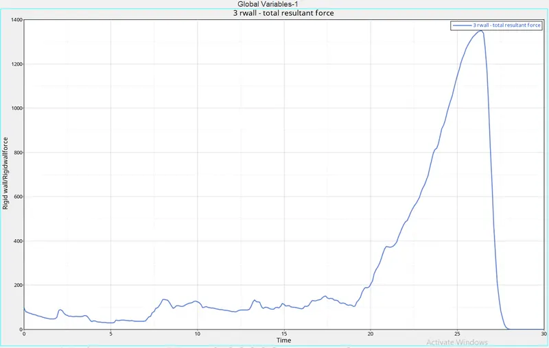
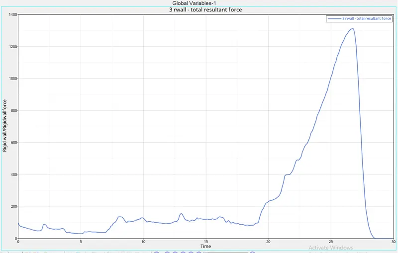
4. Total Resultant forces / RWALL forces:
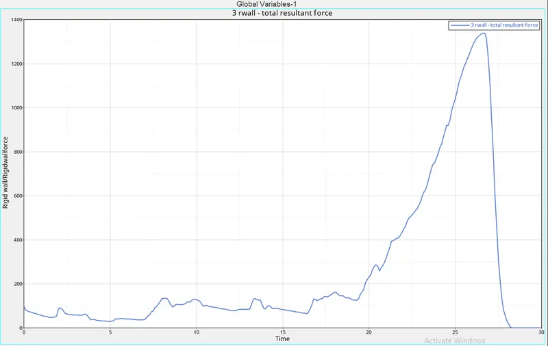
The smallest amount of resultant force is posed by case 6 and therefore the maximum resultant force is posed by case 5. The curve of resultant forces is quadratic. it's also seen that cases 2 and three have an equivalent change in resultant force throughout the motion. The drop by the resultant forces is sudden and becomes zero because the model gets completely compressed. But because the notches just in case 6 are more, they obstruct the entire compression within the normal direction so it doesn't fail completely and still applies force to the rigid wall.
5. Part internal energy:
Here we see that the green and yellow parts have similar internal energies. an equivalent goes for the blue and yellow components. This shows the form of the components .i.e it presence of notches affects the interior energies of the component and also that symmetrical objects have similar internal energies.
In pshell_2mm and pshell2_2mm we see that the height value of internal energy increases because the notches increase. But it's the other for pshell1 and pshell2 components as they do not have any notches altogether in the cases.