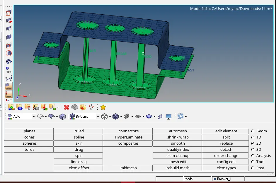
Week 4-1D Element Creation Challenge
AIM:
To create different types of 1D elements in the given model.
Create 1D elements on the following component with given cross-section and DOF
a. Rod element:- Translational DOF should be Constrained with RBE2 link
Cross-Section: BOX- Dimension a= 12 mm
dimension b=10 mm
Thickness t= 0.75 mm
b. Beam element:- All DOF should be constrained with RBE3 link
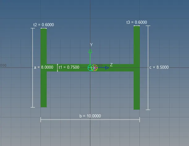
Cross-Section: I Section- Dimension a= 8 mm
Dimension b= 10 mm
Dimension c= 8.5 mm
Thickness t1= 0.75 mm
Thickness t2= .6 mm
Thickness t3= .6 mm
c. Bar element:- Constrain only x and y DOFs With RBE3 link
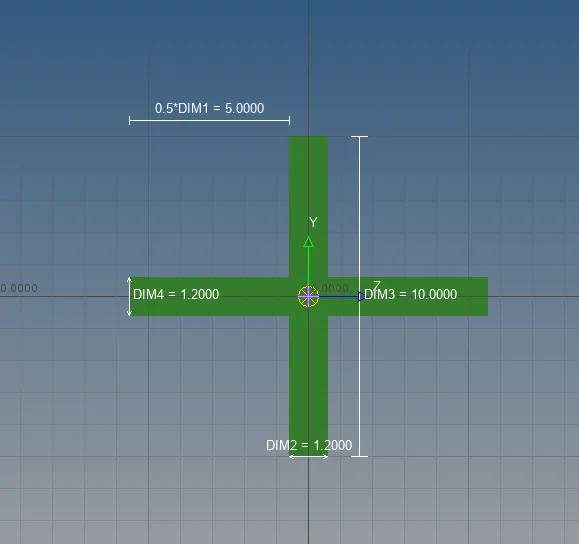
Cross-section: X section- Dimension DIM1= 5 mm
Thickness DIM2= 1.2 mm
Dimension DIM3= 10 mm
Thickness DIM4= 1.2mm
PROCEDURE:
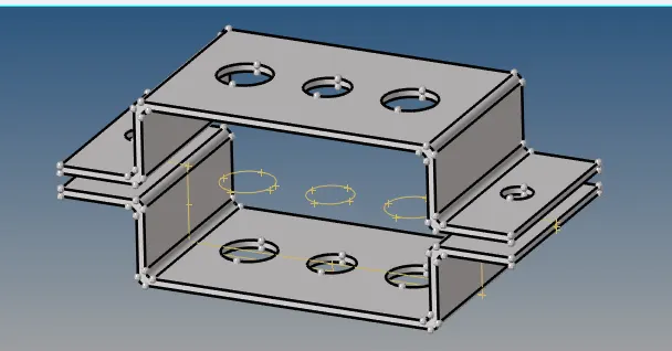
I. Importing geometry:
File-Import-Geometry-(Select file)-Import
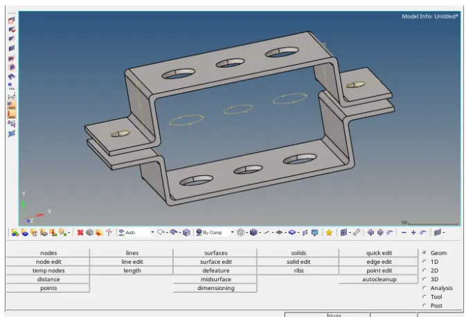
II. Extracting mid surface and deleting solid part
Step 1: Extracting mid surface Geom-mid surface-(Select the surface)-extract
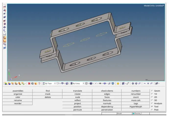
Step 2: Create a new component
(Right-click) Component-create (Here rename as 'Bracket_2')
Step 3: Deleting the solid part and wireframe
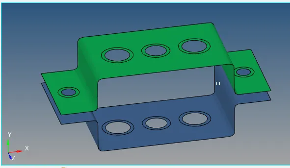
Step 4: Moving one mid surface to 'Bracket_2' Tool-organize-(Select the surface)-Give dest component=" Bracket_2"
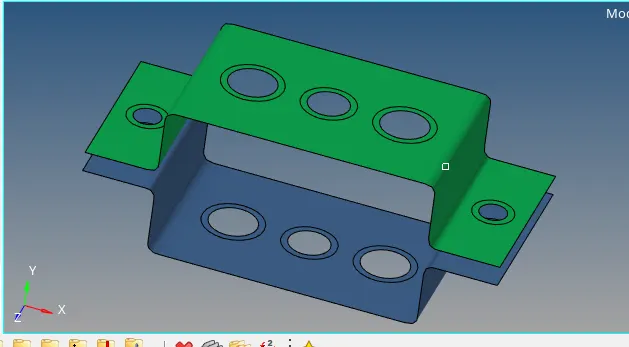
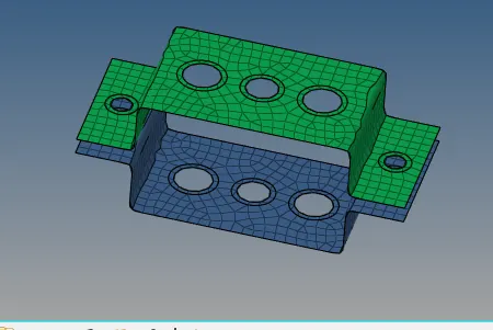
III. Meshing the brackets
Step 1: Creating washer split
Geom-quick edit-Give offset value='5'-(Select the lines)
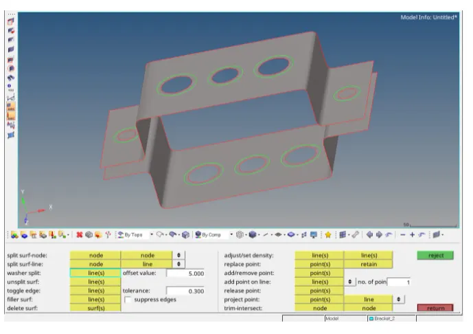
Step 2: Meshing each bracket
2D-auto mesh-(Select the surface)-Give element size='10'-mesh
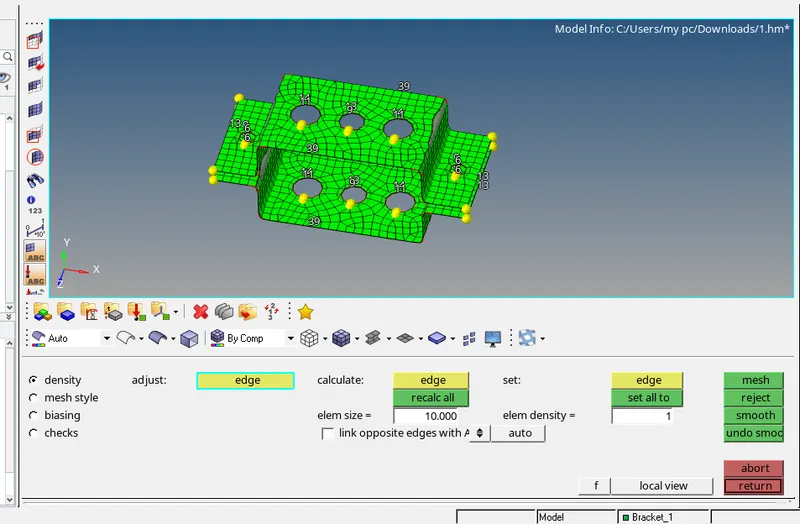
V. Creating material
(Right-click on the model tree) Create-material
Give material name as "Steel"
VI. Creating properties
Right-click on the model tree) Create-Property
We have to create properties for 'Bracket_1', 'Bracket_2', 'Rod', 'Beam', 'Bar' and spring
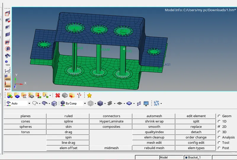
VII. Creating rod, beam, bar, and mass elements
a) Creating a rod
Step 1: Creating RBE2 link
1D-rigid-(Select the nodes)-Uncheck 'dof1', 'dof2' & 'dof3'-create
Step 2: Creating a rod
1D-rods(Select the nodes)-Give property='Rod'
b) Creating beam
Step 1: Creating RBE3 link
1D-rbe3-(Select the nodes)-Uncheck all the 'dofs'-create
Step 2: Creating beam
1D-bar-(Select the nodes)-Give property='Beam' and Elem type='CBEAM'-Give the orientation
c) Creating bar
Step1: Creating RBE3 link
1D-rbe3-(Select the nodes)-Uncheck 'dof1', 'dof2','dof4' and 'dof5'
Step 2: Creating bar
1D-bar-(Select the nodes)-Give property='Bar' and Elem type='CBAR'-Give the orientation
d) Creating masses
Step 1: Creating RBE2 link
1D-rigid-(Select the nodes)-create
Step 2: Creating mass
1D-masses-Give magnitude='10'-Give elem type='CMASS1'-Give property='Bracket_1' or 'Bracket_2'-create
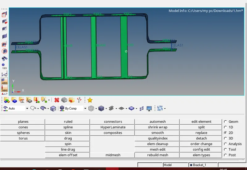
VIII. Creating springs
1D-springs-(Select the nodes)-Give property='Spring' and elem type='CELAS1'
IX. Creating cross-section
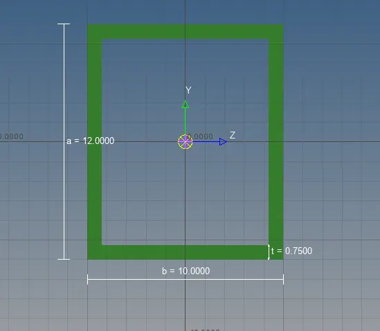
1D-Hyperbeam-Select 'Standard section' (from left options)-Select 'HYPERBEAM' (from standard section library)-create
a) Creating box cross-section
BOX- Dimension a= 12 mm
dimension b=10 mm
Thickness t= 0.75 mm
b. Beam element:- All DOF should be constrained with RBE3 link
Cross-Section: I Section- Dimension a= 8 mm
Dimension b= 10 mm
Dimension c= 8.5 mm
Thickness t1= 0.75 mm
Thickness t2= .6 mm
Thickness t3= .6 mm
c. Bar element:- Constrain only x and y DOFs With RBE3 link
Cross-section: X section- Dimension DIM1= 5 mm
Thickness DIM2= 1.2 mm
Dimension DIM3= 10 mm
Thickness DIM4= 1.2mm
RESULT:
1)The geometry was imported and meshed.
2)1D elements were created on the given component with a given cross-section and DOF.