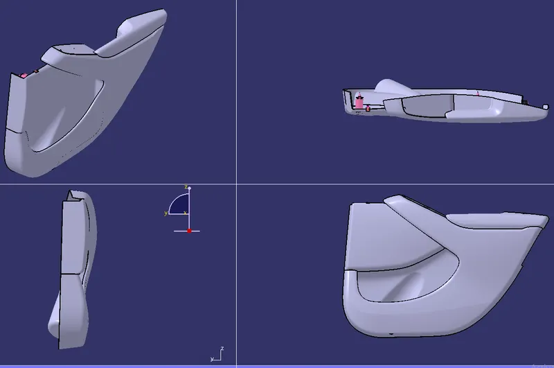
Week 11 - Final project
DEVELOPMENT OF PLASTIC DOOR TRIM PANEL
AIM :To create a B surface and C surface of the door panel for the given A surface and perform draft analysis.
Note:- All Feature sketches and Thickness for the component are taken from the master Section.
A SURFACE OF THE GIVEN GEOMETRICAL SET
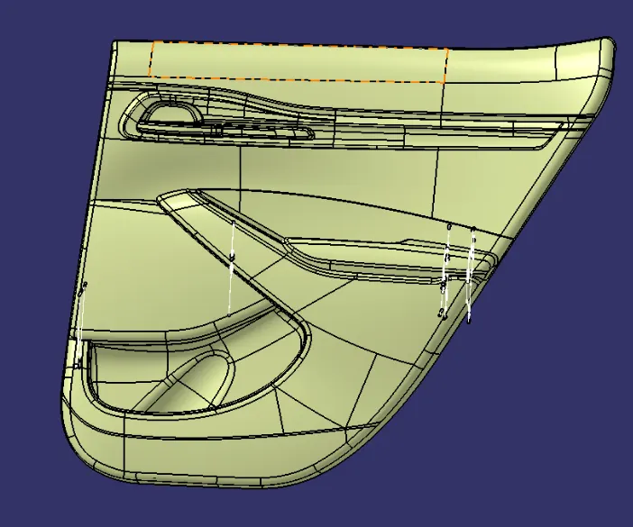
DEVELOPED SURFACE
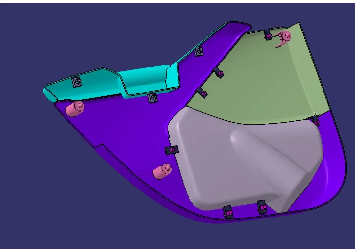
Tools Required
1 Surface Workbench Tools

2 part Workbench Tools

DOOR PANEL : Door panels serve as an interface between the interior of the car and the inner workings of the door, and between vehicle occupants and the door. They are expected to meet a variety of design specifications regarding safety, aesthetics, and functionality.
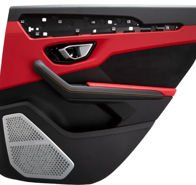
In addition, they are expected to continue the material theme of the dashboard and pillars while concealing intricate electrical and mechanical components for operating locks, windows, and other features.
The door panel has evolved from a simple two-part system of latch and simple winding mechanism to a more sophisticated enclosure. Doors currently have an inner full-width panel consisting of electric windows, central locking system, and speakers. These panels typically consist of a foamed core covered with either textiles or plastics.
The following figure is an example of a door trim: we create the portions of the door panel to create B surface and C surface and then by using the draft analysis features we create draft analysis on the components and then create the B side features of the door panel such as push clips,dog house,screw boss.
A_surface Extraction & Checking Draft Analysis.
Before extracting the A_Surface let's Understand what is A_Surface and how it develops in OEM’S?
In OEM’S there is a Sequence of Operation for every product i.e Design life Cycle
- Concept Sketches
- Class A_creation
- Clay Modeling
- NPD CAD
The Concept Sketch team created a new design on paper ( freehand sketch) taken inputs from the Feasibility Check & Concept validation Team.
After approving the design the styling team takes place and create the A_Surface with the help of Allies Software
From there NPD (New Product Design) team design the component following all the design principle and engineering feature for the production by using different software (CATIA, SOLIDWORKS, NX, etc…,)
I divided the A_Surface into 4 Surfaces for the creation of B&C_Surface And B_Side feature those are Map Pocket, Lower Substrate, and ArmRest by using Multiple extract command.
I checked the boundaries and draft analysis with the tooling axis for the A_Surfacer.
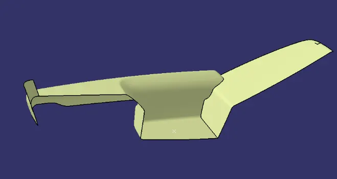
ARM REST CLASS A SURFACE
The above class A surface is extracted from the given geometric set by using multiple extract command from the given geometrical set.
CLASS B
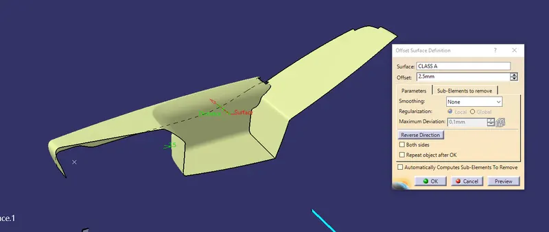
The class A surface is extracted from the geometrical set and then offset to 2.5mm to create Class B surface and then the patches are to be joined.
CLASS C
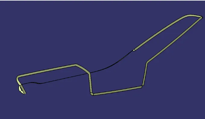
The class C surface is created by using sweep command on the A surface by using the sweep command and then using draft angle of 87 degrees and then sweep along the A surface
After creating the c surface then join the A surface with the C surface and then trim with the C surface to create a closed surface and then using the closed surface command we convert the trimmed component into a Closed surface.
TRIMMED CLOSED SURFACE
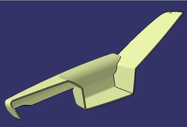
CLOSED SURFACE ARM REST
The above image is the closed surface of the arm rest and create a “TOOLING AXIS” for the arm rest and perform draft analysis and then performs a draft analysis and then check whether the component is used for Drafting .
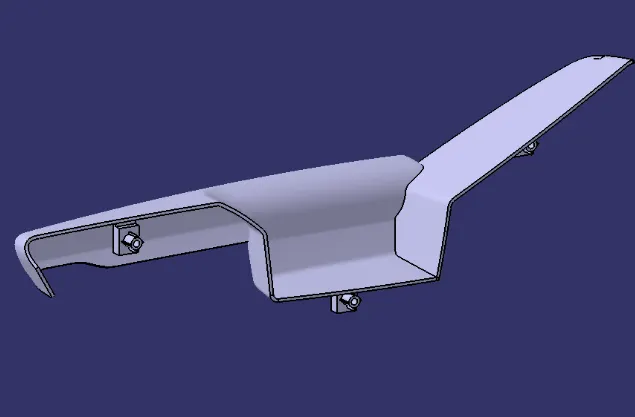
VERTICAL TOOLING AXIS
The above image is a vertical tooling axis created using the point command and then creating a center point of the component and then creating the line along the vertical axis which is Vertical tooling axis .Now choose the draft analysis command and then select the axis system to insert into the vertical axis and then choose the draft point command and then perform the draft analysis on the command .
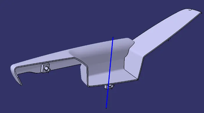
As we can see from the above image the component can be drafted and is suitable for drafting some parts of the component cannot be drafted from the above image so we create another axis along the component and perform the draft analysis.
LIFTER TOOLING AXIS
The above picture is horizontal tooling axis created on the component and then perform draft analysis with the lifter tooling axis
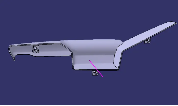
DRAFT ANALYSIS FOR THE ARM REST
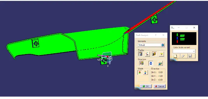
From the above image we can see that draft analysis on the component along the lifter tooling axis and the component can be drafted.
MAP POCKET UPPER SUBSTRATE
CLASS A
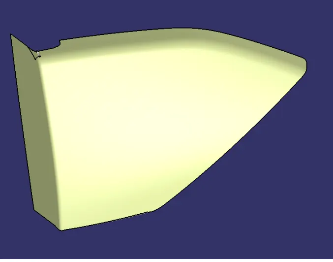
The above image is map pocket upper substrate which has been extracted from the given geometrical set by using multiple extract command and then offset the class A surface to 2.5 mm to create class B surface
CLASS B
Class B surface is created by using offset command and then selecting the multiple extract command and a distance of 2.5mm is selected and class A surface is created .
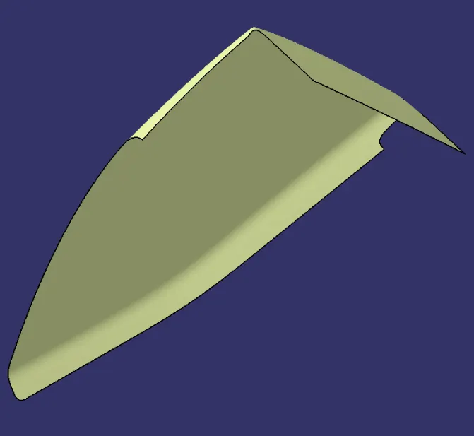
CLASS C SURFACE
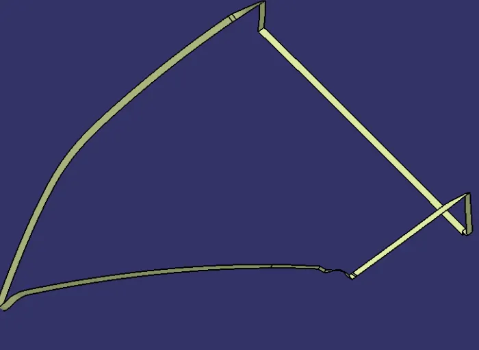
For creating the class C surface we select the class A surface and using the sweep command and then select the boundary of the class A surface and then giving the angle of 87 degrees and selecting the class A surface as the reference create the C surface along the class A.
TRIMMED CLOSED SURFACE
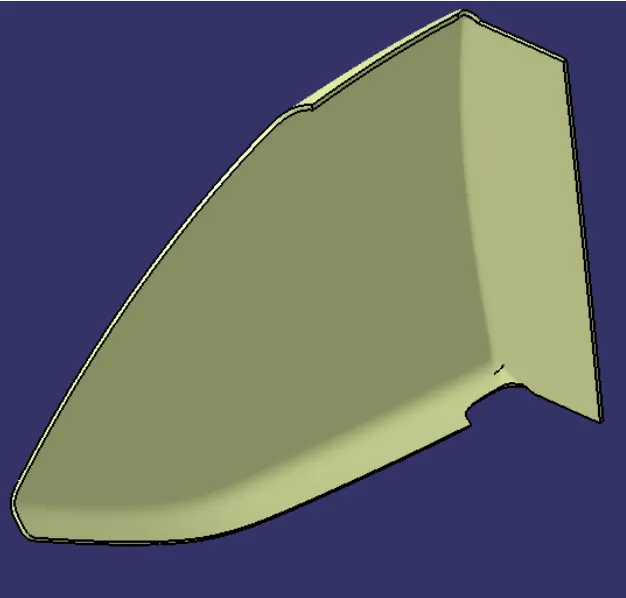
After creating the trimmed surface by Joining class A surface and class C surface we get a closed surface when we trim the class A with class B by using the closed surface command we select the trimmed surface and create a closed component
CLOSED SURFACE
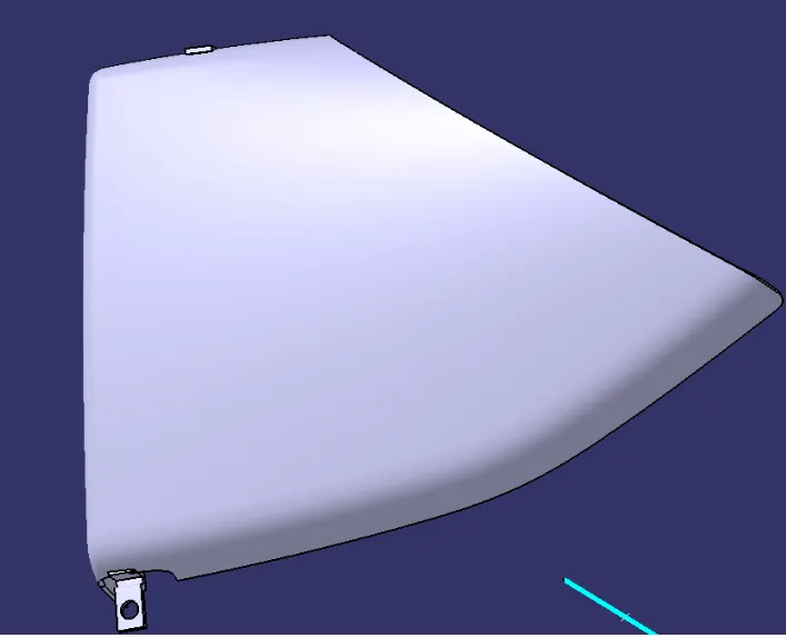
The above image is the closed surface of the arm rest and create a “TOOLING AXIS” for the arm rest and perform draft analysis and then performs a draft analysis and then check whether the component is used for Drafting .
DRAFT ANALYSIS
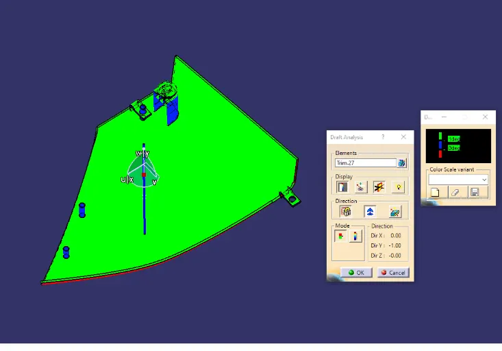
As we can see from the above image the component can be drafted and is suitable for drafting some parts of the component cannot be drafted from the above image so we create another axis along the component and perform the draft analysis .
MAP POCKET LOWER SUBSTRATE
CLASS A
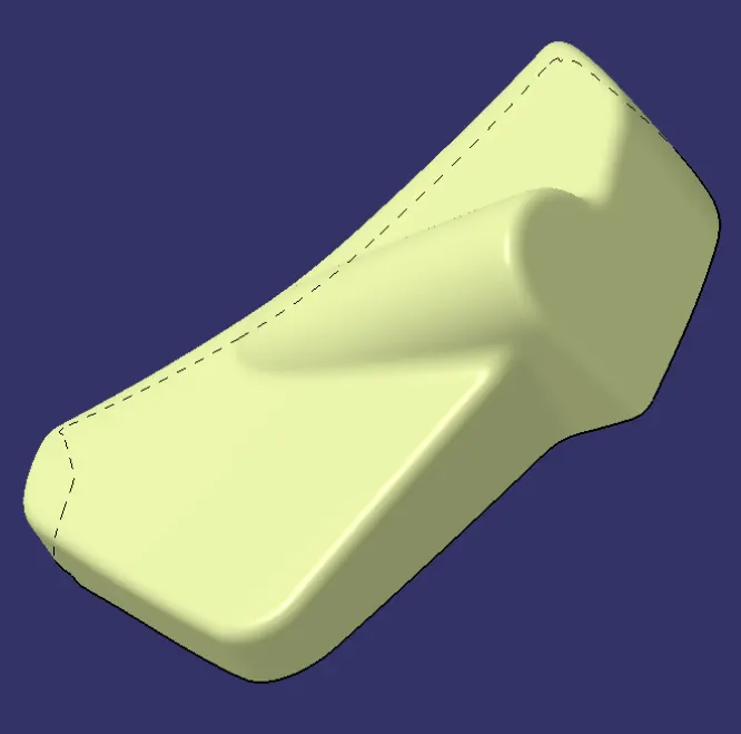
For creating a class surface we select the multiple extract command and select the surface from the geometrical set and then class A surface is created
CLASS B
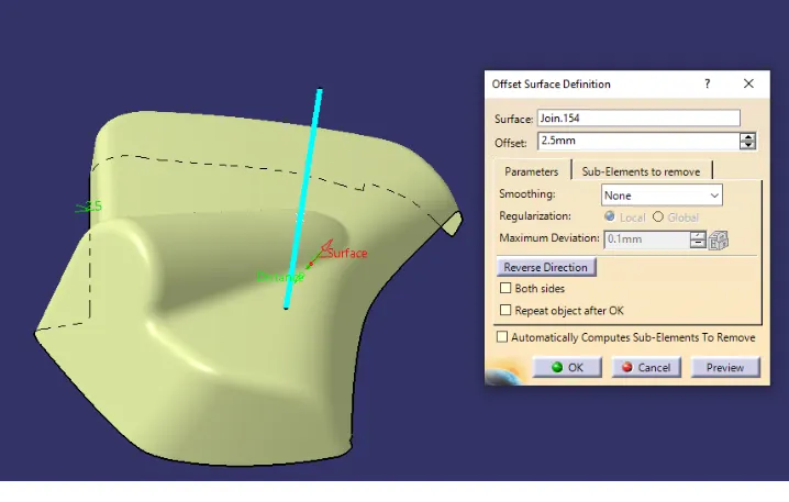
Class B surface is created by using offset command and then selecting the multiple extract command and a distance of 2.5mm is selected and class A surface is created .
CLASS C
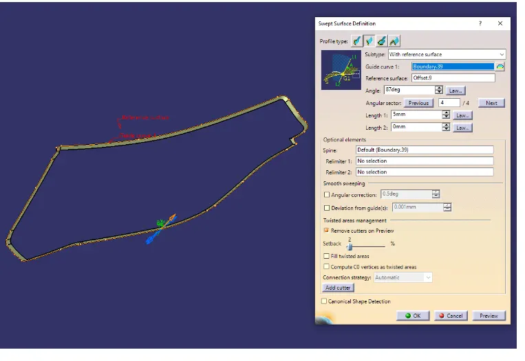
For creating the class C surface we select the class A surface and using the sweep command and then select the boundary of the class A surface and then giving the angle of 87 degrees and selecting the class A surface as the reference create the C surface along the class A.
TRIMMED CLOSED SURFACE
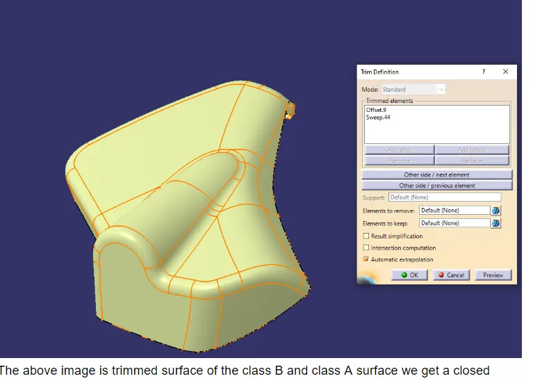
The above image is trimmed surface of the class B and class A surface we get a closed surface by using the closed surface command we select the trimmed surface and then create a closed surface of the component
CLOSED SURFACE MAP POCKET LOWER SUBSTRATE
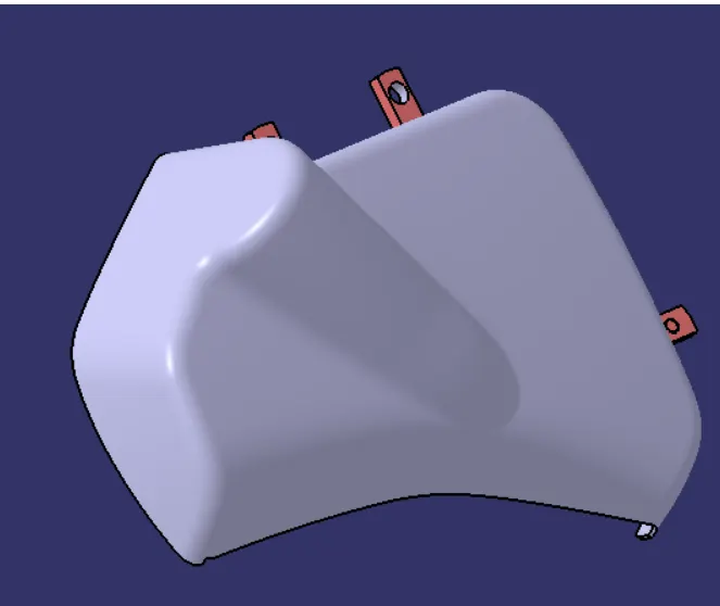
The above image is the closed surface of the lower substrate of the map pocket and create a “TOOLING AXIS” for the arm rest and perform draft analysis and then performs a draft analysis and then check whether the component is used for Drafting .
DRAFT ANALYSIS
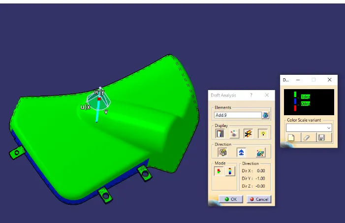
AS we can see from the above picture the component can be drafted along the vertical axis
LOWER SUBSTRATE
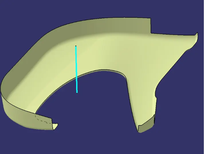
CLASS A
The class A surface is created by using the multiple extract command and then extract the surface from the given geometrical set and we get a class A surface
CLASS B
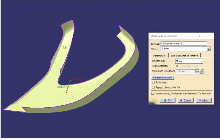
For creating the class B surface the class A surface is offset to 2.5mm to create the class B surface
CLASS C
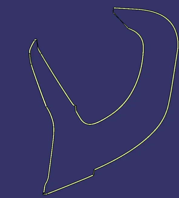
For creating the class C surface we select the class A surface and using the sweep command and then select the boundary of the class A surface and then giving the angle of 87 degrees and selecting the class A surface as the reference create the C surface along the class A
Now trim the A surface with class c surface and then we get a closed surface by selecting the close surface command and select the trimmed surface and we get a closed surface of the component and then we can perform draft analysis
DRAFT ANALYSIS
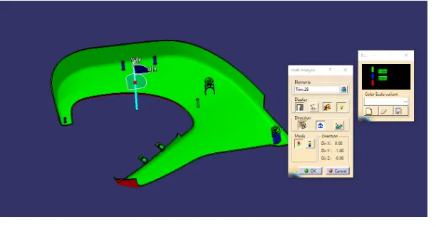
AS we can see from the above picture the component can be drafted along the vertical axis
COMPLETE CLOSED SURFACE OF DOOR TRIM PANEL
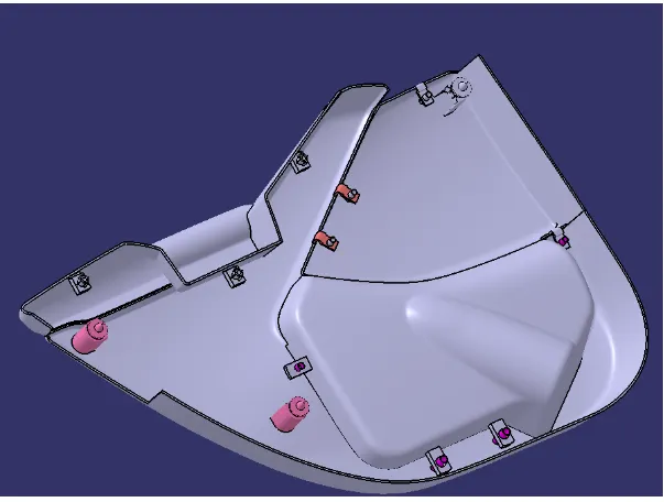
Features are commonly found in injection molding designs. They are used to aid in the assembly of molded parts by providing a channel between the Plastic component and Sheet metal. Some of the features are
- Ribs
- Flanges
- Heat Stakes
- Screw boss
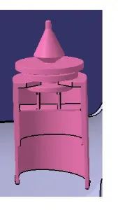
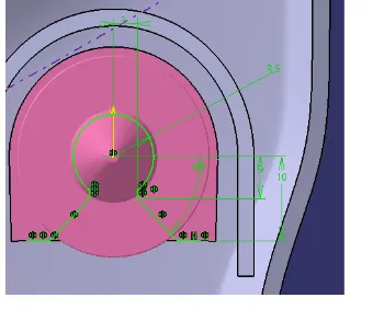
- Dog House
- Push Clip
SCREW BOSS AND DOG HOUSE
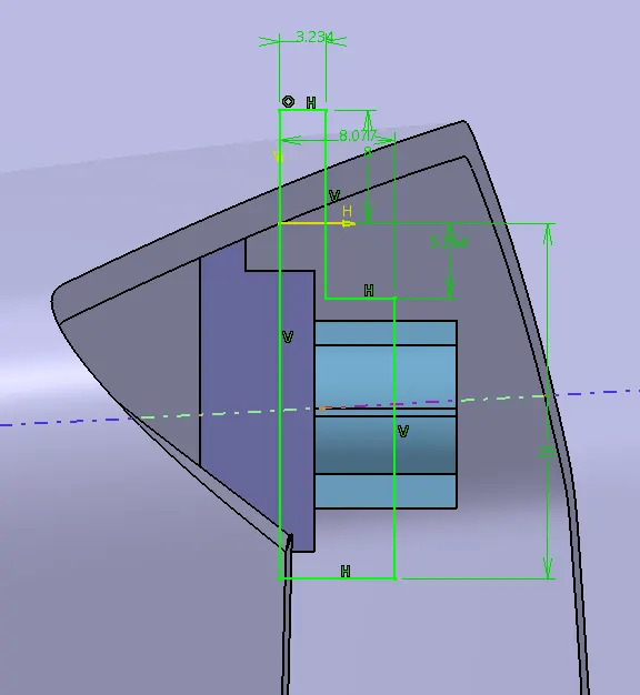
SKETCH
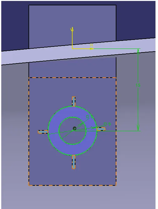
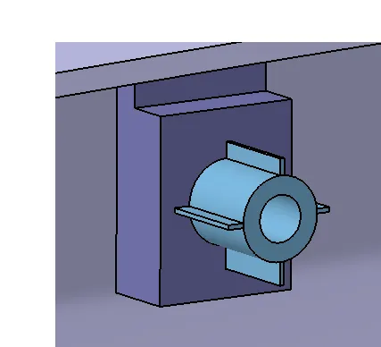
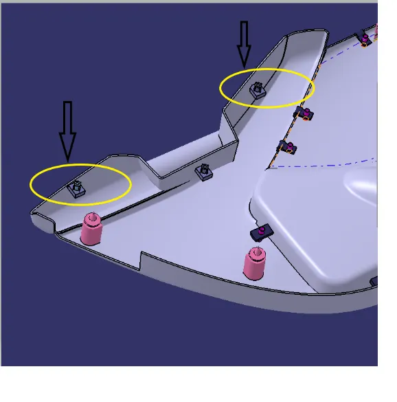
HEAT STAKES
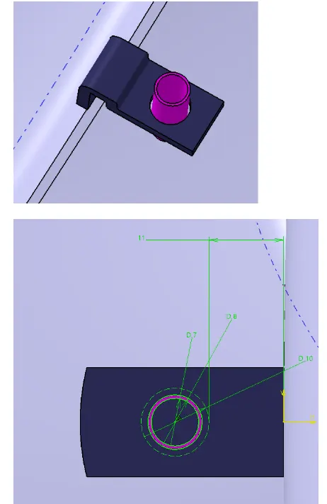
PUSH CLIPS
SKETCH
DRAFT ANALYSIS
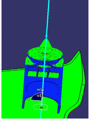
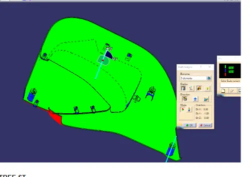
TOTAL DRAFT ANALYSIS OF THE COMPONENT
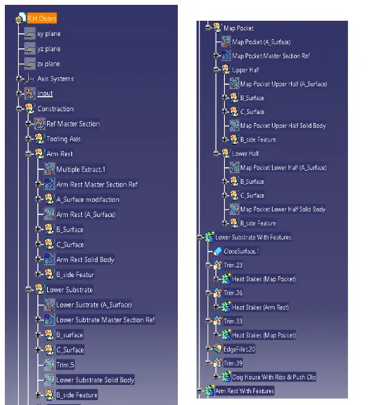
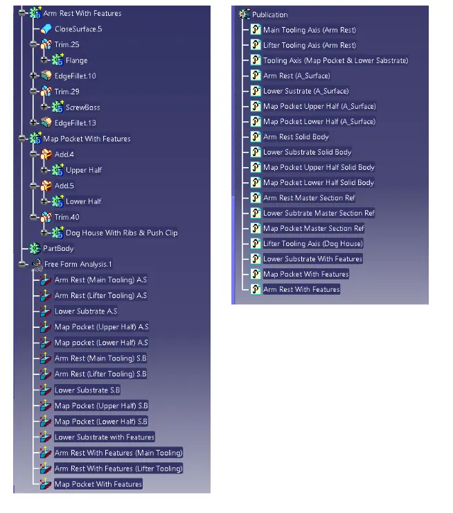
TREE STRUCTURE
ISOMETRIC VIEW
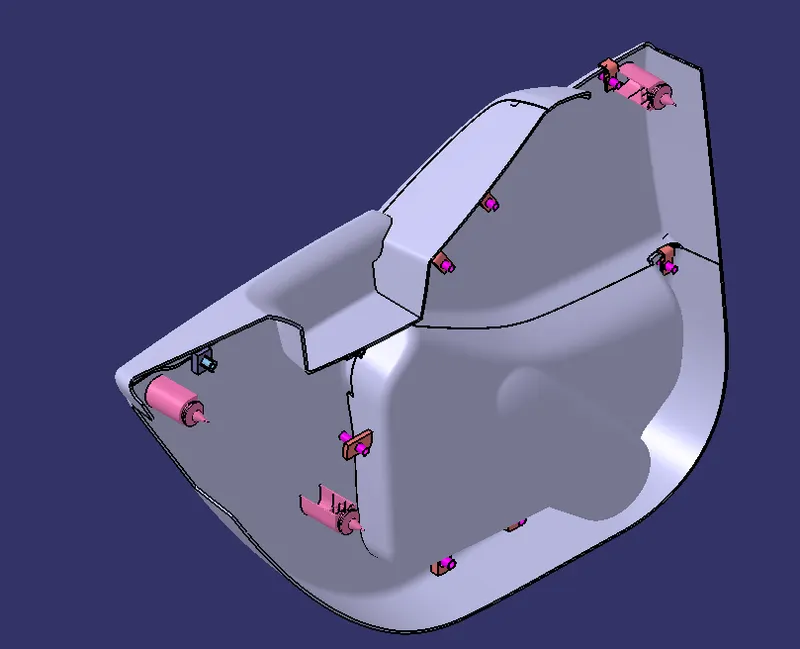
TYPES OF ORIENTATION OF DOOR TRIM