Assignment 3-2D Element Formulation Challenge
OBJECTIVE: To Compare the results with base simulation and improved shell element properties.
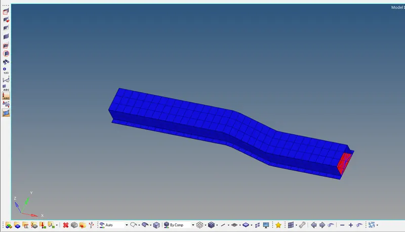
Import:The given rad file is imported to hyperworks and is displayed as below.
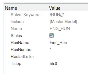
Changing run time to 55ms
In model tree, under CARDS collector, ENG_RUN card have a Tstop of 60, which is changed to 55.
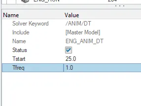
Changing animation steps to 40:
To have 40 animation steps, the frequency should be Run time/Animation steps = 55/25 = 1.0
In model tree, under CARDS collector, ENG_ANIM_DT card have a Tfreq of 1.0.
The base simulation is run without any modification to element properties using Radioss option under Analysis tab.
Create a folder to save the rad files in local directory.

edit options providing number of threads as -nt 4
After analysis, the .OUT file is viewed to check whether the Energy error and mass error fall within the aceptable range.
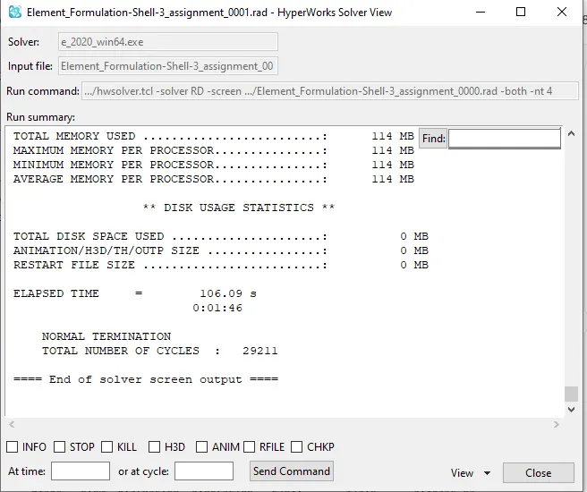
The energy error starts from 0% to 10% which is within acceptable range.
Since the error values are acceptable, rigid wall forces, internal energy, hourglass energy, contact energy, total energy of the simulation are plotted with the help of hypergraph 2-D.
hyperview is opened to view the simulation (deformation of the crush tube).
model and results (h3d file) are loaded from the newly created folder.
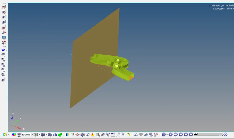
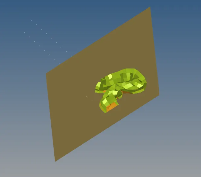
animation shows how the crush tube deformes (displacement)under the action of force.
To plot the specific graphs, hyper graph 2-d is selected.
File named-Element_Formulation-Shell-3_assignmentT01 is opened.
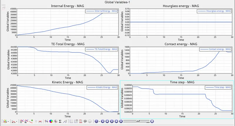
Specified energies are plotted against time on the same plot as shown below:
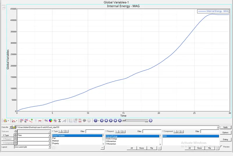
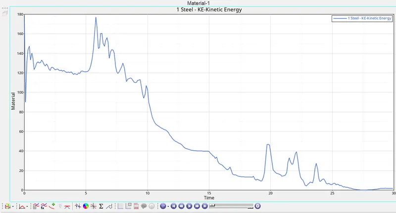
From the plot obtained for base simulation without any modification to element properties, following observations are made:
Internal energy increases throughout the simulation which is due to the force developed on tube due to deformation.
There is a constant floow in hourglass energy throughout the simulation.
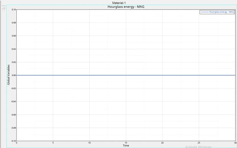
Contact energy remains zero throughout the simulation.
Total energy of the system has a slight decrease from the start to end of the simulation.
A new plot is created to plot the rigid wall forces.
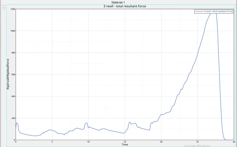
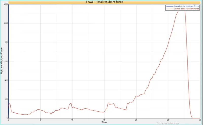
Total resultant force and Resultant normal rigid wall forces are plotted against time as shown above.
The rigid wall force curve is of a non-linear behaviour, which is due to the variation in the force exerted by the crush tube on the wall throughout the simulation.
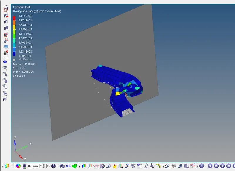
Contour plot of Hourglass energy is obtained using contour option under hyperview.
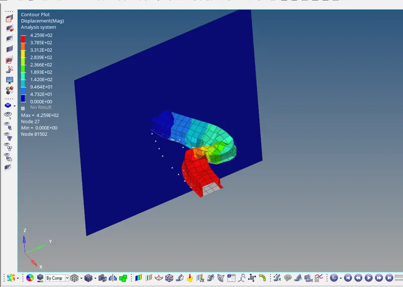
Contour plot of Displacement is obtained using contour option under hyperview.
CASE 2
| Parameters | Comment | |
|
Ishell =24 |
QEPH 4 nodes shells are best combination of cost and accuracy. | |
|
Ismstr=2 |
Full geometric nonlinearities (default)with possible small strain formulation activation in RADIOSS Engine. | |
|
Ish3n=2 |
Standard 3 noded shell (C0)with modification for large rotation(default) |
|
| N=5 | Number of integration points set to 5 for accuracy bending. | |
|
Ithick=1 |
Thickness change is taken into account for accuracy. |
|
|
Iplas=1 |
Iterative plasticity for good accuracy. |
Hourglass energy
Total energy
Rigid wall
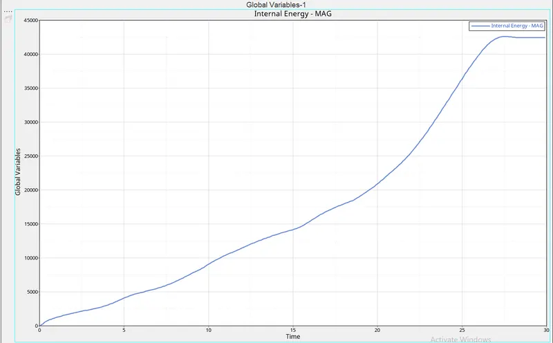
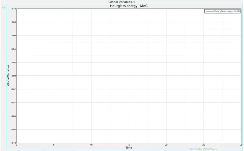
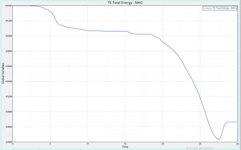
When recomended properties are changed from the base values, simulation results shows that
- Total Energy remains constant rather than decreasing which is clear from the energy error which went till-10% now changed to -0.1%.
- Hourglass energy which was constant throughout the simulation.
- Contact energy characteristics are same in both cases.
- Internal energy is having a gradual increasing characateristics in both the cases.
- Rigid wall forces also decreased to a lower value than that of default value rigid wall force value.
- Contour plots shows that there is a slight increase in maximum displacement of element with recommended property values
Hourglass:Hourglass is a deformation, that is noticed when an element is deformed due to the applied load. But the strain energy due to this deformation is not recorded for that element". It is also known as "Zero energy deformation modes" where an element is seen deformed.
It indicates instability
It is also said to be as, non-physical mode of deformation, that occurs in reduced or under integrated elements produces no stress.
Usually, it can be seen in the post-processing stage, where the elements will have zig-zag formation.