Week 9-Creation of 1D Connectors Challenge
Creation of 1D Connectors
OBJECTIVE:
To mesh the given geometry and create 1D connectors at desired locations using Hypermesh.
The following connections have to be realized in each respective component
1.Right_Rail_2 and Front_truss_1:-Seam-Quad(angled+capped+L)
2. Left_Rail_2 & Front_truss_1:- Quad elements
3. Front_truss_2, Front_truss_1 & Right_Rail_1:- Spot weld with 2 Layers and 5 mm Diameter
4. Front_truss_2, Front_truss_1 & Left_Rail_1:- Hexa (Adhesive)
5. Rear_truss_2 & Right_Rail_2:- Bolt Connector
6. Rear_truss_2 & Left_Rail_2:- Bolt Connector
7. Right_Rail_1 & Right_Rail_2:- Spot-weld with Rigid Elements
8. Left_Rail_1 & Left_Rail_2:- Spot-weld with Spring Elements
9. Rest all the component left Join them with suitable connectors.
PROCEDURE:
Import the .hm model and the connector points in the model tree are hidden while meshing.
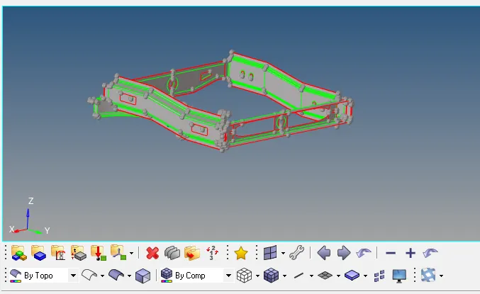
- Each individual component is separated and meshed seperately.
- If required, the components can be cleaned for topological errors and defeatured using manual or autocleanup method.
- To clean geometrical errors: Geom - autocleanup - set parameters - clean
2D surface Meshing and Mesh refinement
- To generate a shell mesh over each component
- 2D - automesh - surfs (displayed) - target length =5 - specify elem type and order - mesh
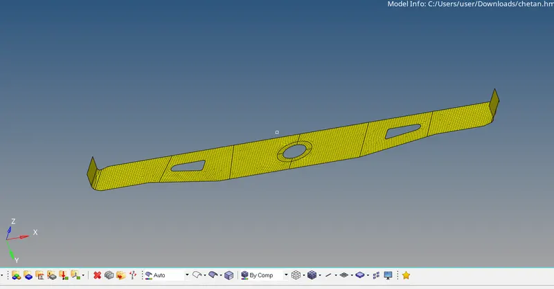
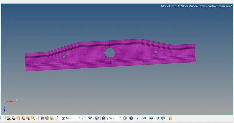
- However to achieve a perfect mesh without quality errors the comp is sectioned into different surfaces using surf trim option and meshed separately.
- Since volume tetras arent being generated, the surfaces can be meshed with quads majority
Rear_truss_2 & Left_Rail_2:- Bolt Connector
Specify the location of the bolt by selecting two single nodes at a certain distance in one of the component since two bolt connectors are being realised
Select the two components which has to be fixed by the bolt
Specify the search length (about 10mm)
The realised bolt connection is shown below
Rear_truss_2 & Right_Rail_2:- Bolt Connector
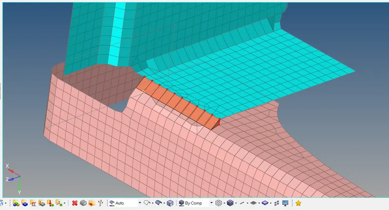
Right_Rail_2 & Front_truss_1:- Seam-Quad(angled+capped+L)
To create a seam weld: Connectors - seam
Select the nodes (by path) on one of the component
tolerance = Specify the search distance (10mm
Select the two components and keep the imprint check on
weld type is set as seam-quad (angled+capped+L)
The spacing is set a 5mm. Spacing defines the distance between the two adjacent weld elements
Left_Rail_2 & Front_truss_1:- Quad elements
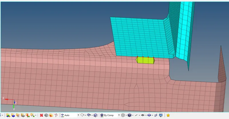
Seam-Quad elements
For: Left_Rail_2 and Front_truss_1
To create a seam weld: Connectors - seam
Select the nodes (by path) on one of the components
tolerance = Specify the search distance (10mm)
Select the two components and keep the imprint check on
weld type is set as quad and the spacing (distance between the two adjacent weld elements) is kept as 5mm
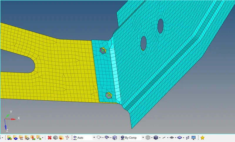
Front_truss_2, Front_truss_1 & Right_Rail_1:- Spot weld with 2 Layers and 5 mm Diameter
To create a spot weld: 2D - connectors - spot - type=weld
Select all the required nodes where the location of the spot weld has to be placed.
Then select all the 3 components
Specify a diameter of 5mm and number of layers as 3.
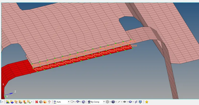
Front_truss_2, Front_truss_1 & Left_Rail_1:- Hexa (Adhesive)
To create a seam weld: Connectors - seam
Select the nodes (by path) on one of the component
tolerance = Specify the search distance (10mm)
Select the two components and keep the imprint check on
weld type is set as hexa (adhesive) under the weld type category.
The strips and coats of the weld can be altered. In this case, the strip is set as 2 and a single coating is specified
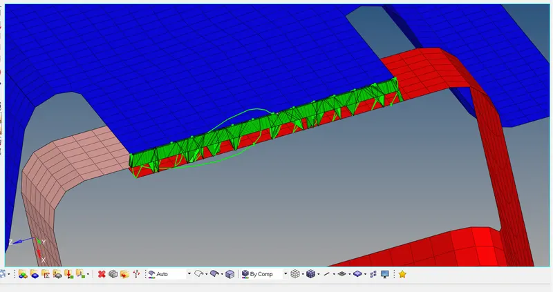
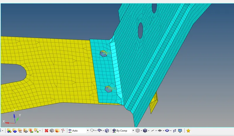
Right_Rail_1 & Right_Rail_2:- Spot-weld with Rigid Elements
As similar to previous spot weld creation, this spot weld is created using rigids instead of weld
To create a spot weld: 2D - connectors - spot - type=rigids
Select all the required nodes where the location of the spot weld has to be placed.
Specify the diameter and number of layers as 2 (since only two components are present)
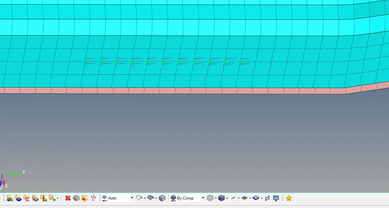
Left_Rail_1 & Left_Rail_2:- Spot-weld with Spring Elements
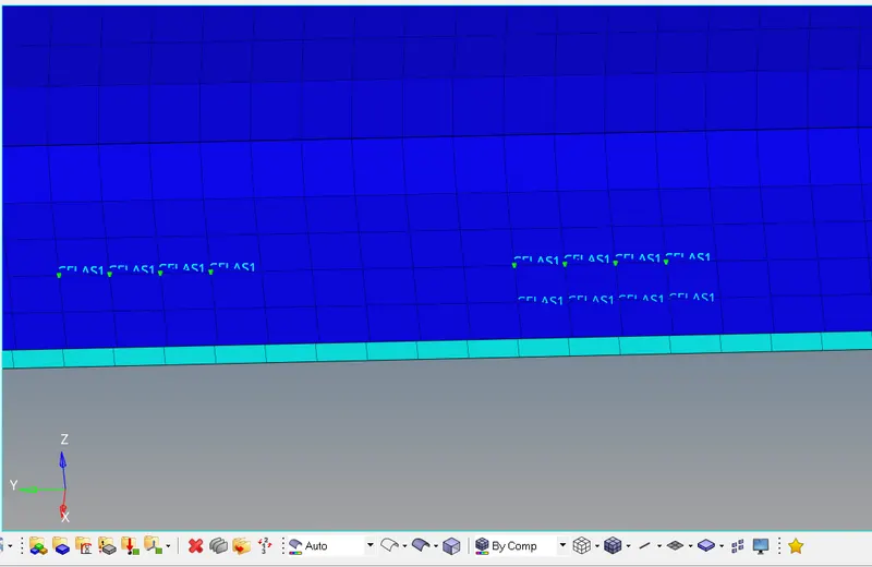
Similarly as done for the previous case, here the spot element type is set as spring instead of rigid or weld
CONCLUSION:
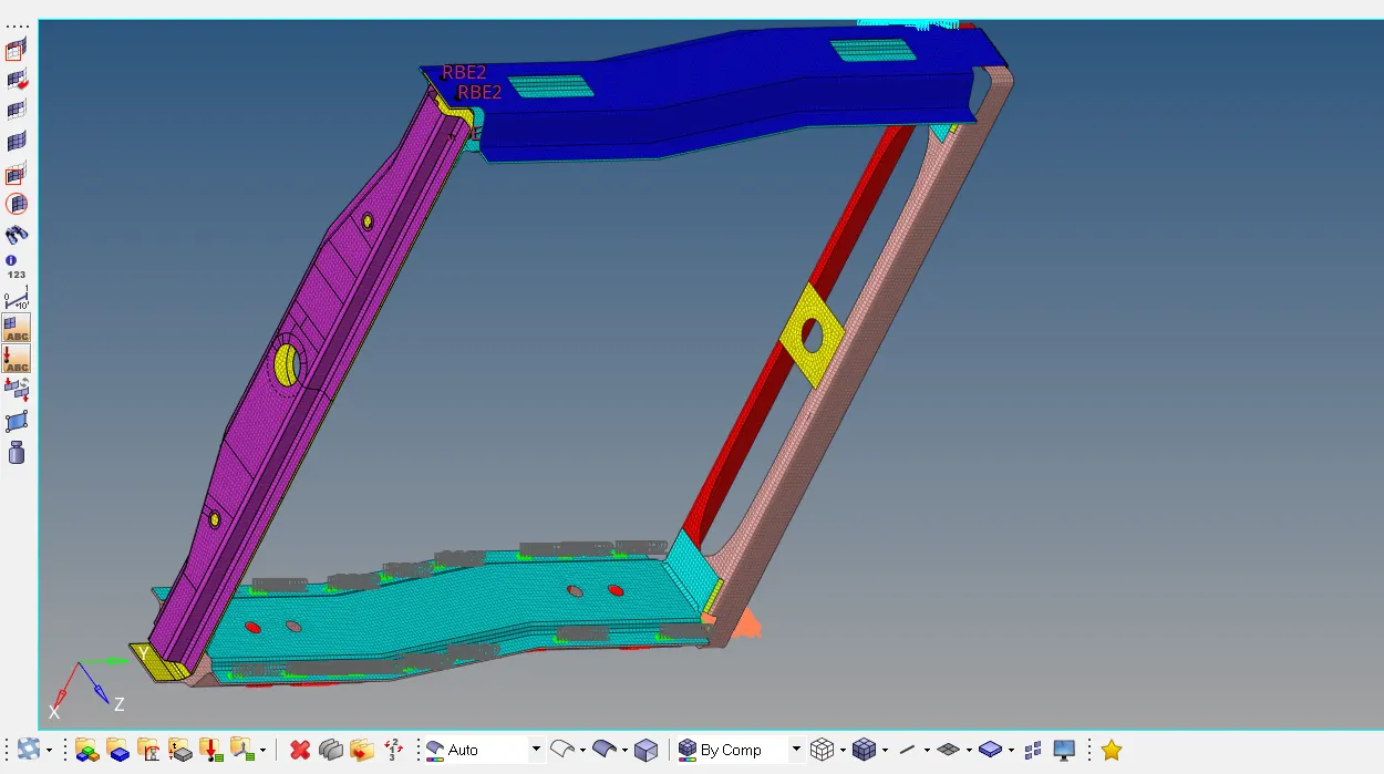
Hence every components have been meshed and required connections have be defined and sucessfully realized.
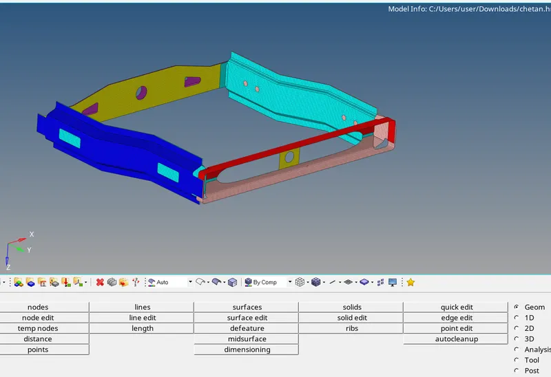
Finally the entire connections and meshed components are shown below