Week 9: Project 1 - Surface preparation and Boundary Flagging (PFI)
Aim - Surface preparation and Boundary Flagging (PFI)
Introduction-
The purpose of task is to do boundary flagging and surface preparation for the given geometry. After that we will run the simulation for no hydrodynamic case setup and see the motion of piston and valves in cylinder for better understanding.
Steps –
- Geometry
- Define the boundary
- Case setup
- Simulation
- Post processing
- Outputs
- Conclusion
Geometry –
Import the file in the converge.
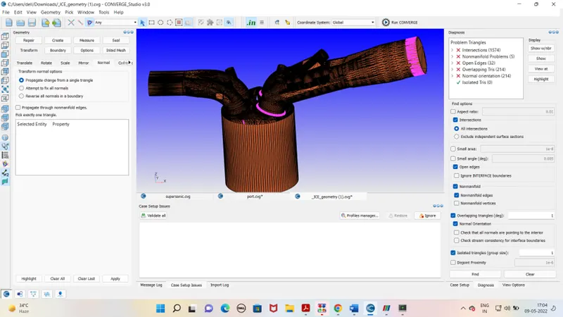
- From the diagnosis it It is seen that our geometry I shaving problem in triangle as showed in above figure.
- Intersection error of geometry is correct by translating the parts.
- Normal orientation error of geometry is corrected with translating the normal.
- Open edges of geometry is corrected with repair command.
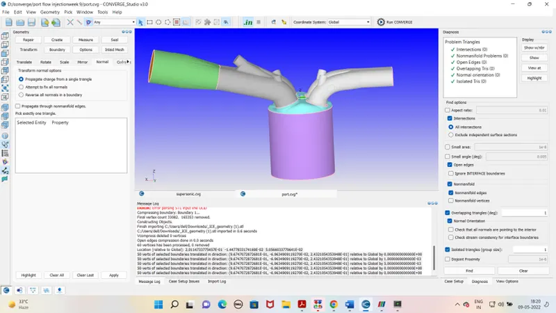
After boundary flagging and surface preparation our geometry is looks as shown below,
Case setup –
Application type –
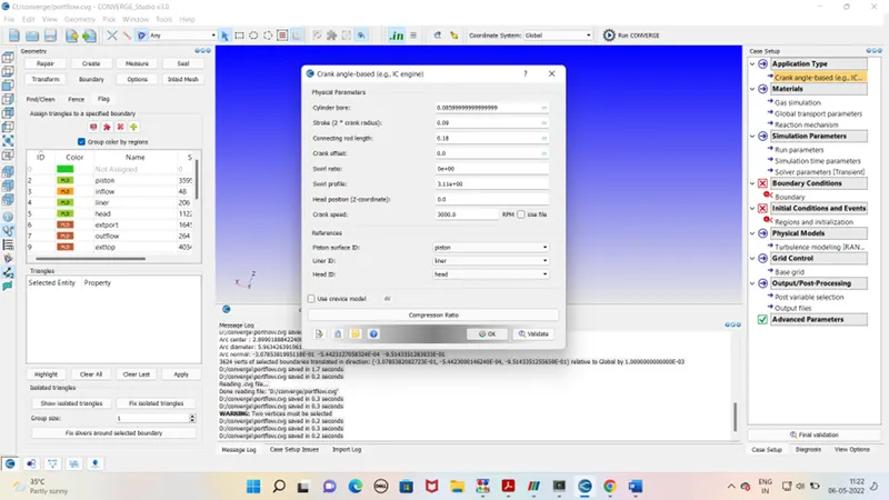
Choose Crank angle based application type. Enter the cylinder bore stroke and other details from engine specification sheet.
Pre defined mixture
Gas simulation –
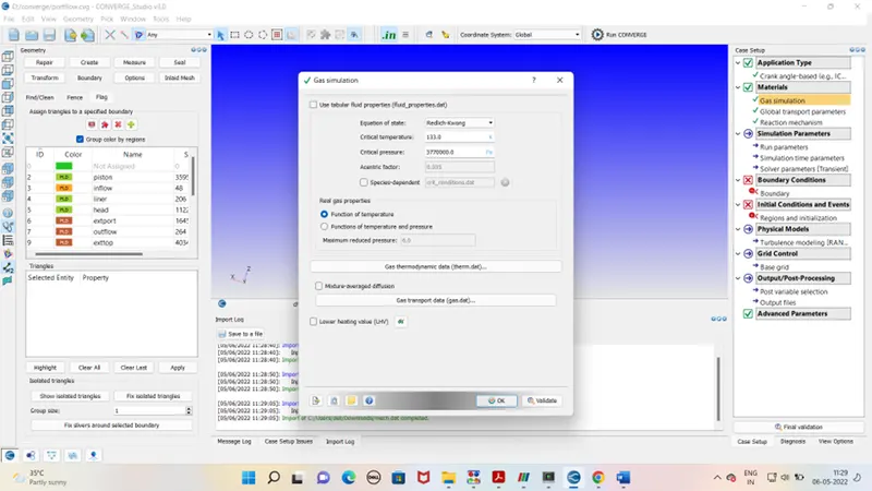
Select the Redlich kwong equation for gas simulation. the critical temperature and pressure are already pre-defined. Import the therm.dat file in gas thermodynamic data.
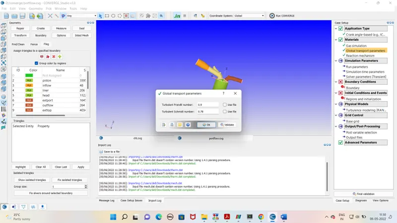
Global transport parameter –
Turbulent Prandtl no and Schmidt no is mentioned below.
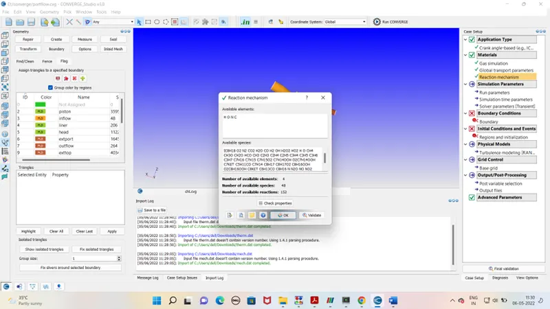
Reaction mechanism –
For reachion mechanism import mech. Dat file for reaction data of all species.
Simulation Parameter –
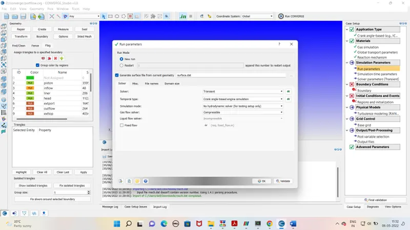
Run parameter –
We will run the simulation for transient solver. Simulation mode will be no hydrodynamic.
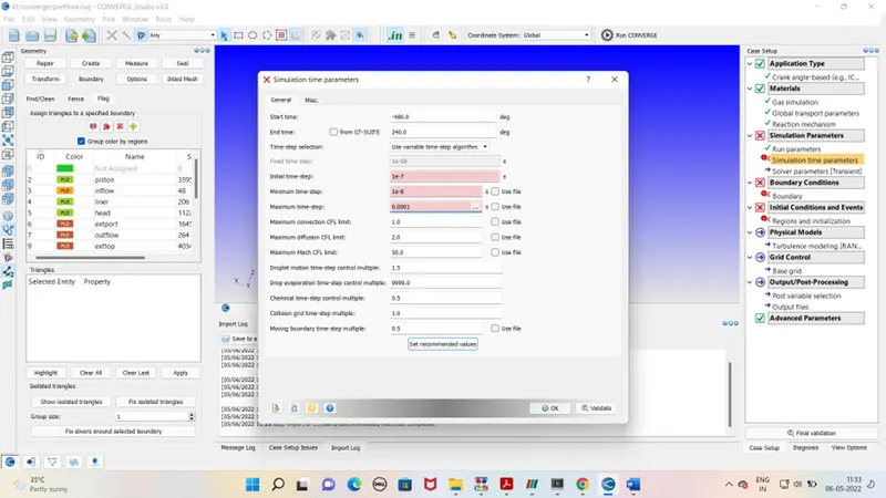
simulation time parameters-
start time and end time for simulation will be as follow .
Solver parameters- Default
Boundary condition –
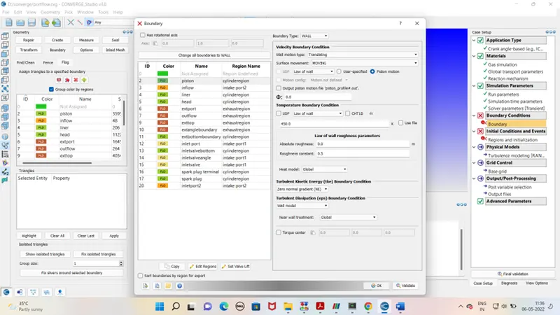
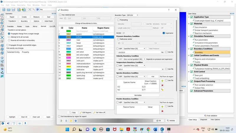
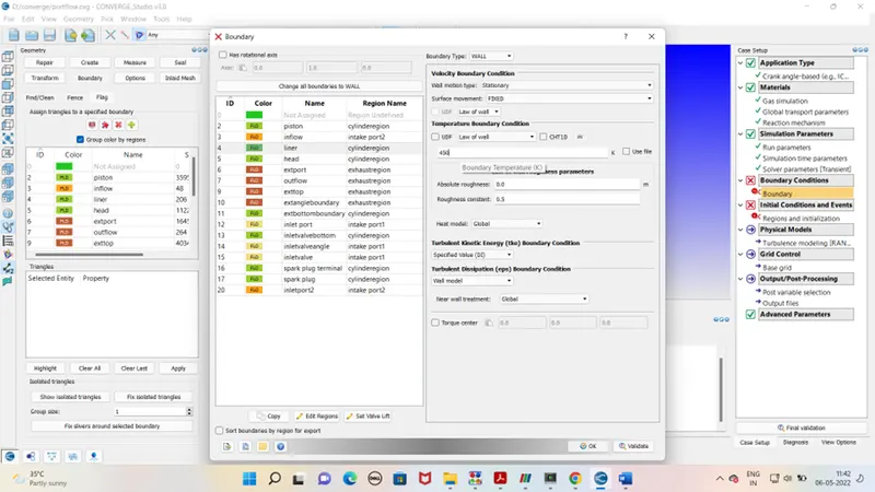
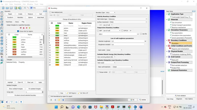
Boundary condition for different boundary is as follow –
- Piston
- Inflow
- Liner
- Head
- Ext port
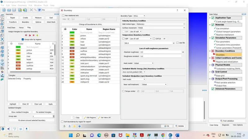
- Outflow
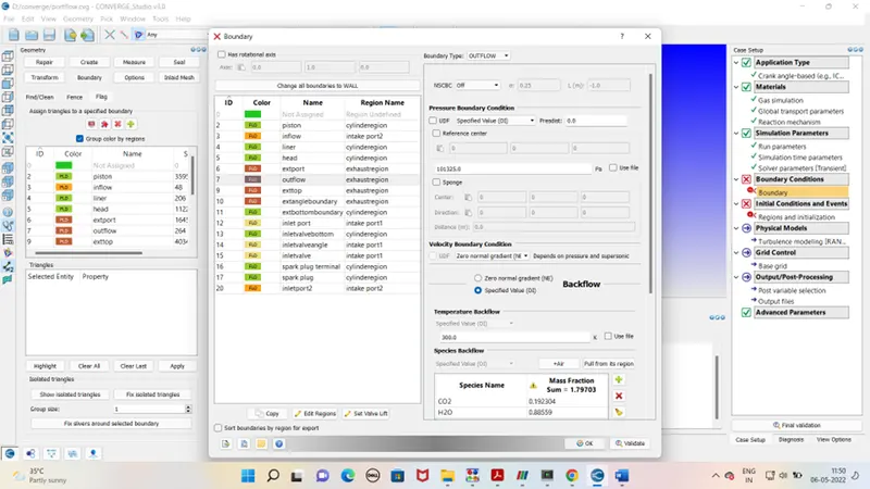
- Ext valve top
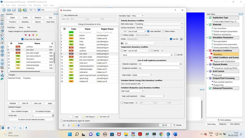
- Ext valve angle boundary
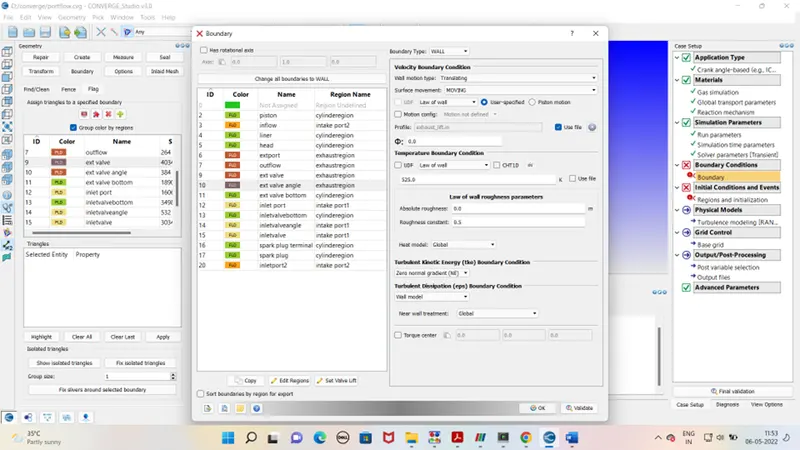
- Ext valve bottom boundary
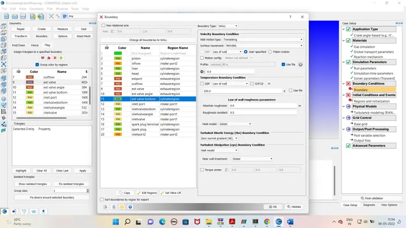
- Inlet port
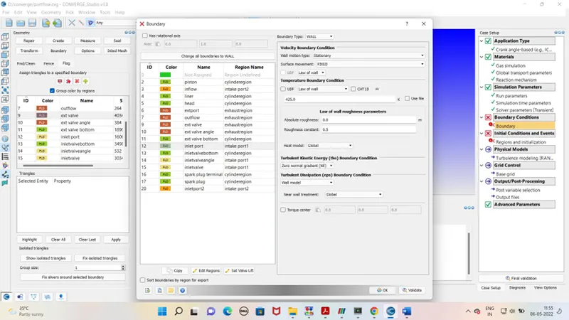
- inlet valve bottom boundary
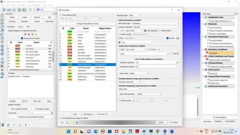
- inlet valve angle boundary
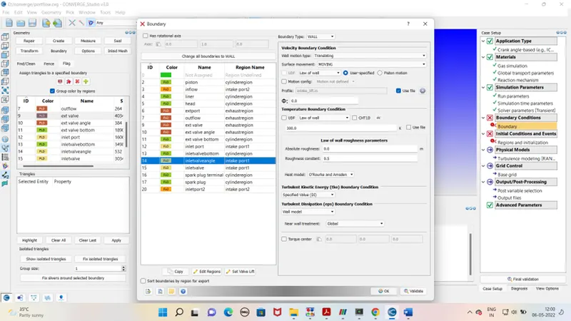
- inlet valve top
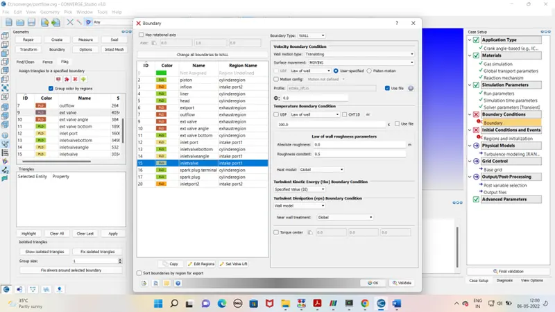
- spark plug terminal
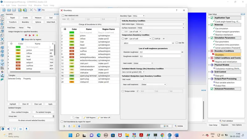
- spark plug
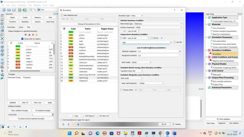
- inlet port2
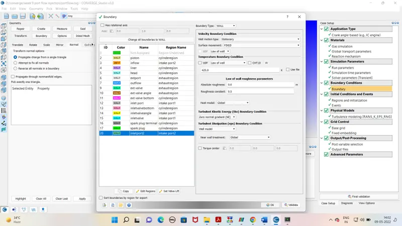
Intial condition and events –
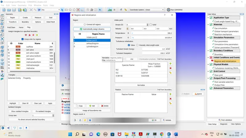
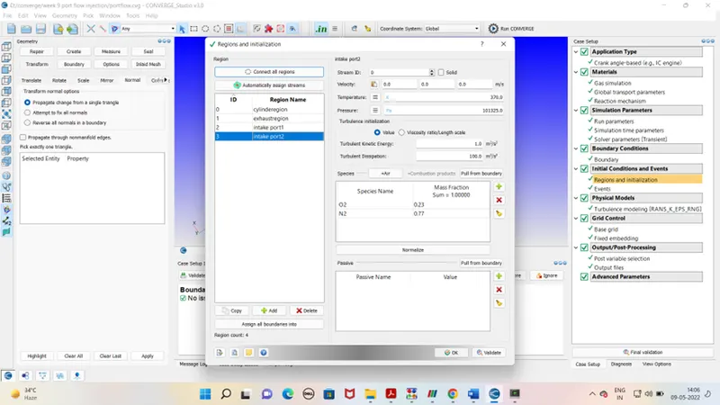
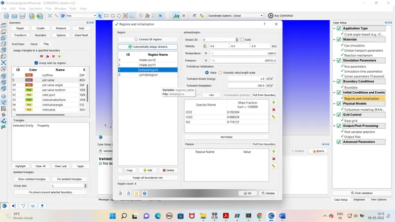
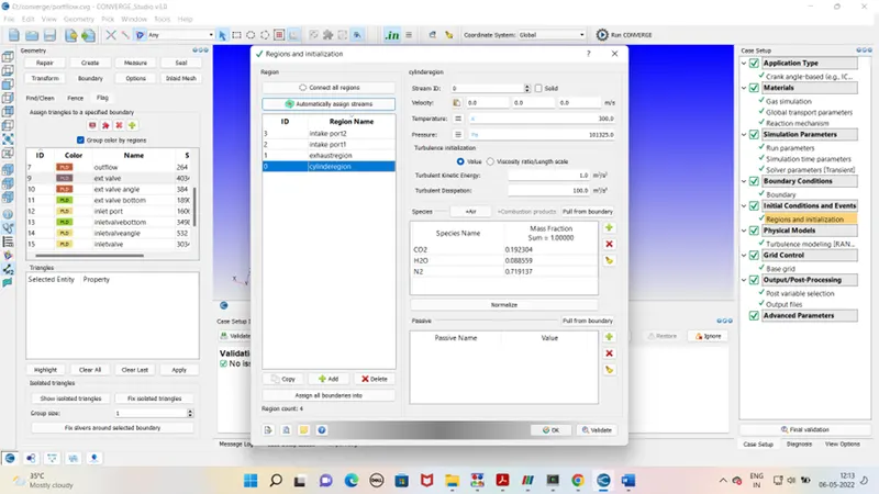
Basically as per geometry 4 region are defined that is
- intake port1
- intake port2
- exhaust region
- cylinder region
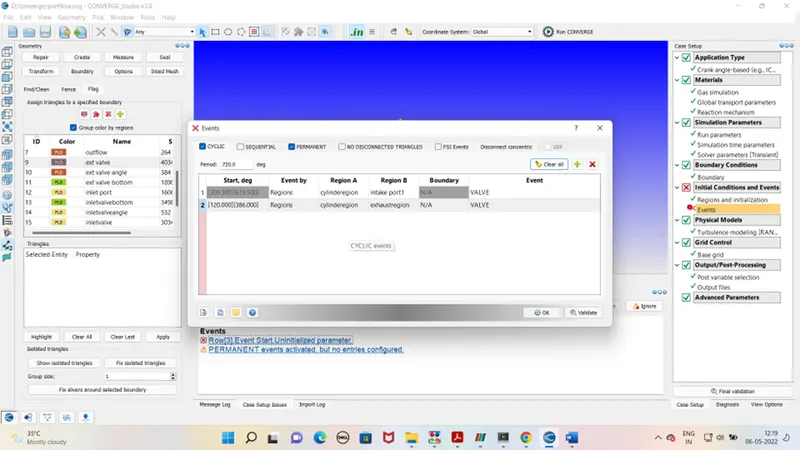
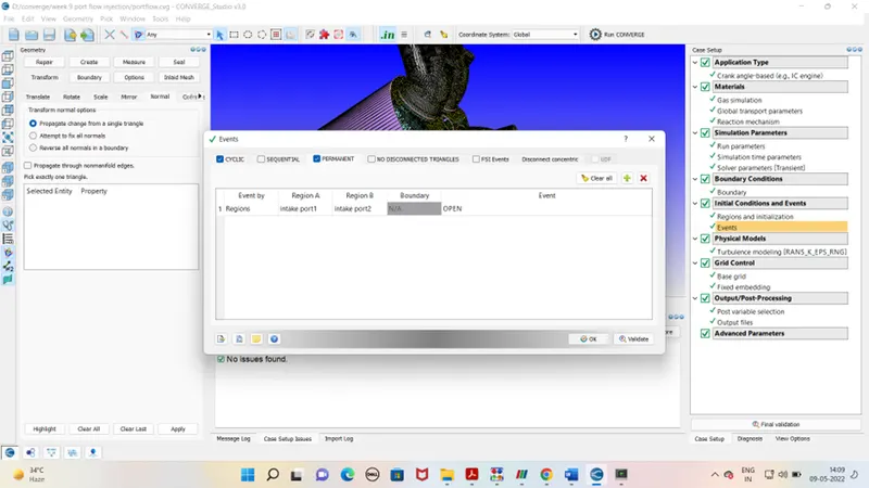
Events –
As per the valve timing of inlet and exhaust valve the cylinder region has to connected and disconnected . events are defined below in cyclic tab for inlet valve , exhaust valve and cylinder region
For inlet port 1 and inlet port 2 event is defined in permanent tab .
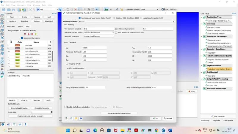
Physical models –
Grid control –
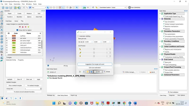
Base grid – dx - 0.004
dy – 0.004
dz – 0.004
Output processing Advanced parameter - Default
After case set up exports the file to defined folder. Run the simulation in the Cygwin. Generate the output files. As output file is generated run the post processing in Cygwin again. Open the output file in paraview for the mesh view and simulation
Outputs –
Mesh -
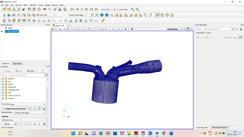
Simulation link-
https://youtu.be/rIQX1XZI6zA
Conclusion – After all the geomtery correction output files are run in paraview. For given geomtery the simualtion is shown in above link. In this process is non hydrodynamic. Piston movement is clealy visible from animation.