Week-11 : Discretization of 3D intake manifold using GEM-3D
AIM- Understanding the concept Discretization. GEM 3D method to convert 3D model to 1D for simulation. And how Discretization plays major role in the simulation.
Discretization- It is process of dividing the given volume of part in sub volume.
Discretization length - It is length of each sub volume.
Task 1 -
Comparision case 1 and case 2 for discretization length 40 mm and 0.1 mm for intake runner respectively.
Case setup is as follow.
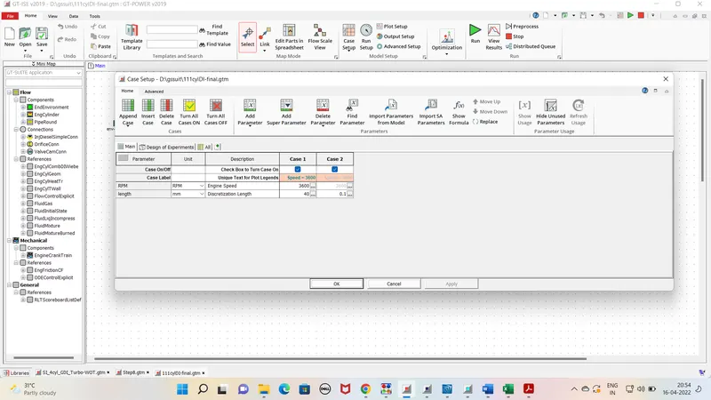
Outputs Parameters - Torque, BSFC, max cylinder pressure and simulation time are as follow -
| Particular\Cases | 1 | 2 |
| Brake Torque [N-m] | 96.2 | 95.9 |
| BSFC [g/kW-h] | 238.2 | 238.9 |
| max pr. | 117.11 | 115.17 |
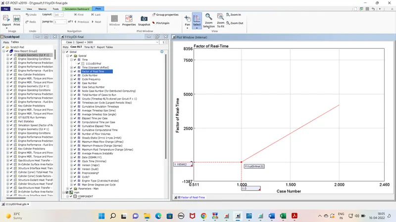
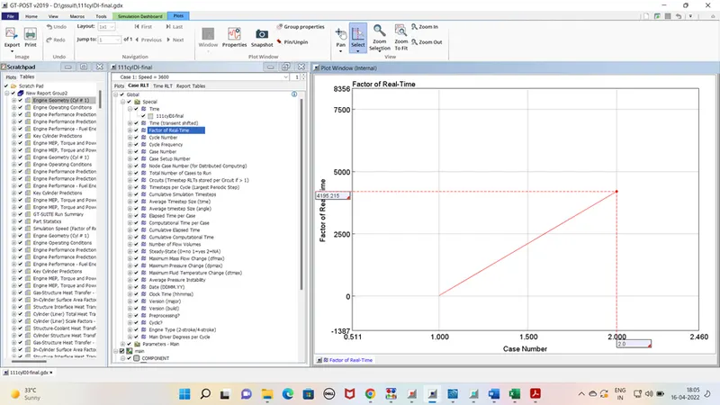
Simulation time graph
case 1
case 2
Remarks-
From simulation results it is noticed that there is no such difference in the bsfc , bp, and maximum pr. But case 2 is approx 4000 times slower than case1 simulation because Discretization process took long time to solve the equations beacuse of its Discretization length .
Task 2 - Building intake manifold from STL model.
Step 1 -
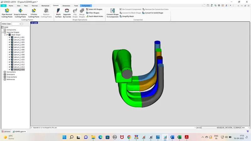
Import 3D model from the non linear(standard) folder in acoustics directory.
Step 2 -
Select the model and go to the command seprate by curve in convert function to convert the model in sub parts as per different profile/ shape . Now remove the ends caps of the model to indicate inlet and outlet of model.
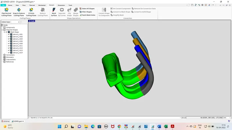
Step 3 -
Now we have to seprate the runner from manifold. select the command 3 points cutting plane in convert function. Select 3 points at base of runner and clip it carefully so that manifold surface not to be trimmed.
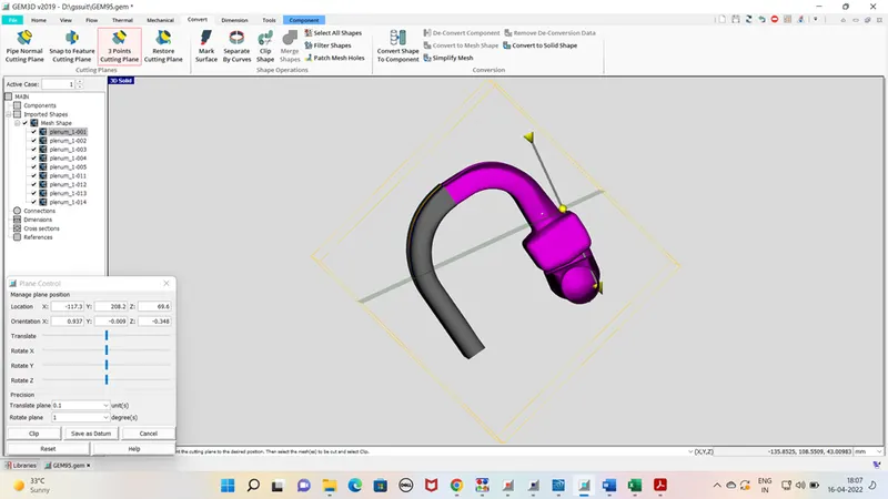
Step 4 -
now convert this entering part of runner in pipes by selecting add connection command in convert shape to component by clicking right on runner.describe the flow direction, diameter and fluids conditions.
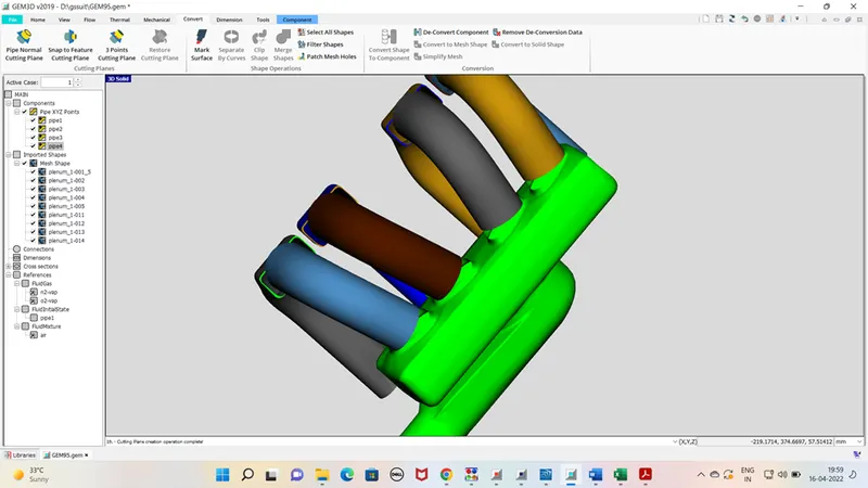
similarly convert the second half of runner in pipes with same procedure.
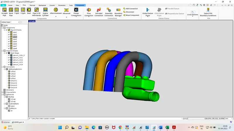
Step 5 -
now add the orifice connection at entry of each runner . otherwise software will consider it as straight pipe assembly only. click right on runner go to add connection and define the entry point . do it for all runner.
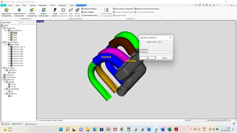
Similarly do it of outlet connection of runner.
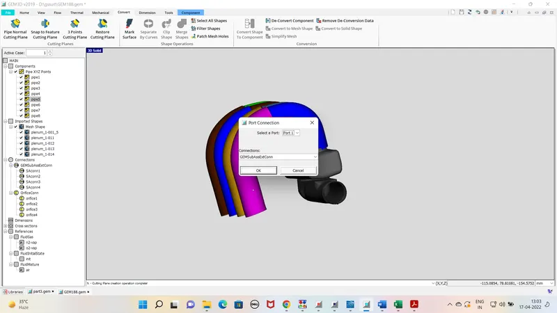
Step 6-
Now select the entry of manifold and divide it in two parts by selecting pipe normal cutting plane command in convert function. clip it from the point where dia is changing suddenly. now add the sub component by adding connection and define its inlet and outlet points.
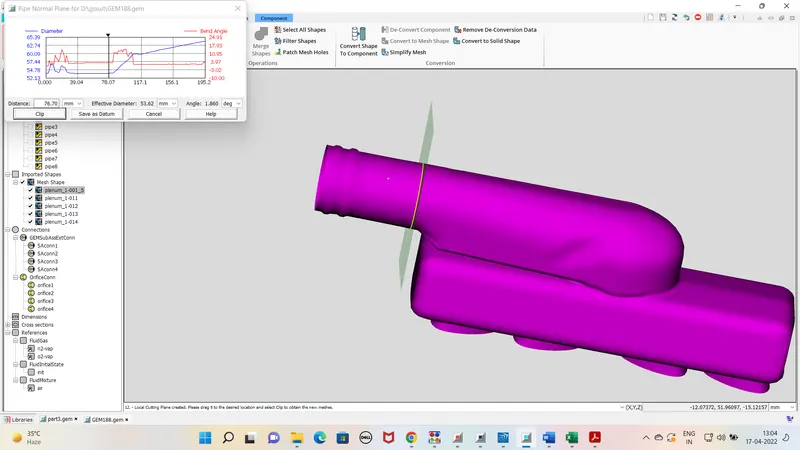
similarly do it for next pipe connection as well.
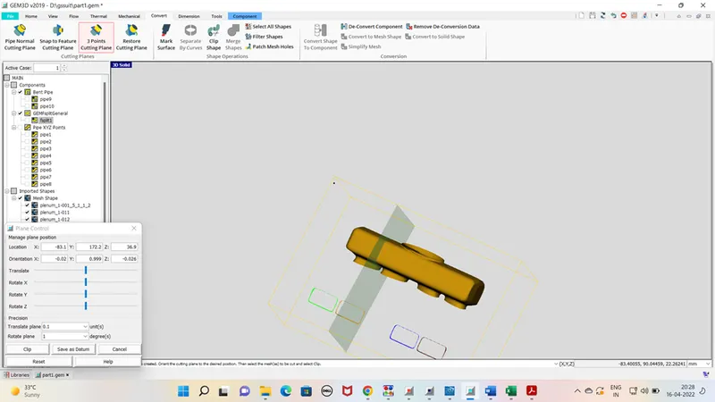
step 7 - Remove the manifold the inlet pipe connection with 3 point cutting plane command. now we are left with manifold only. now divide it into again in two flowslip parts with 3 point cutting plane command. define its entering and exit points.
step 8 - Now all the conncection has to fixed this is done with help of flow connection and flow extrusion command in flow tap.
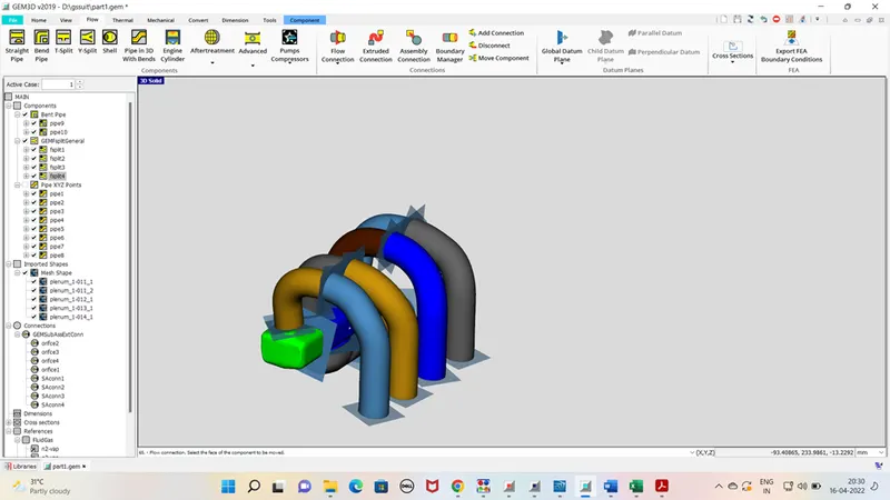
step 9 -
Now select the model and selct the export gt model from home tap and select dicretize. and model will be generated.
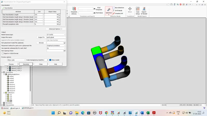
Remarks - dicretization plays major role in the calculation. so its has to defined as per standard formula. smaller is the length , longer time it will take to simulate the model.