Week 4.2: Project - Transient simulation of flow over a throttle body
Aim- Setup and run transient state simulation for flow over a throttle body.
In this case we run the simulation for transient state. everything will be same as it was in steady state simulation. But in this we will rotate the throttle to see the changes in flow.
Setup -
Time for simulation -
In steady state flow the velocity at inlet was 203 m/sec . And length of the pipe approx. taken as 0.2m. so it velocity will take 0.000985 sec to travel across the length.So for 5 periods it will take .005 seconds.
Case setup –
Case setup changes for throttle –
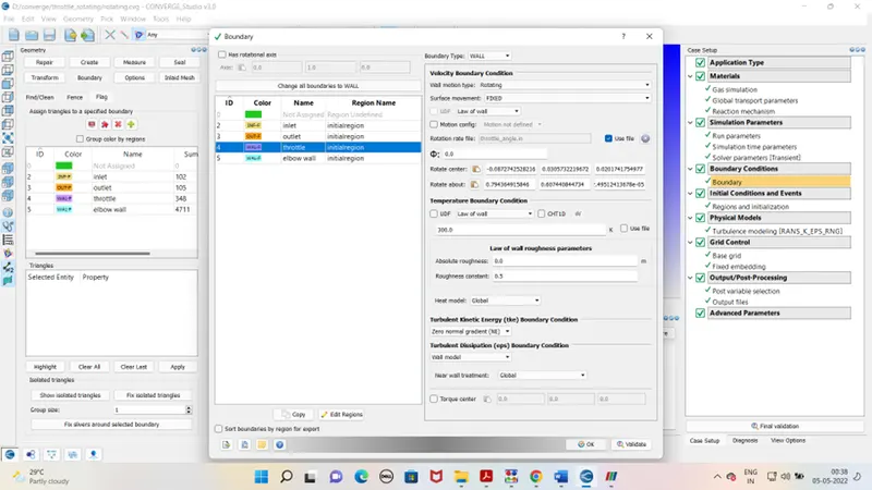
Base grid – dx - 0.002
dy – 0.002
dz – 0.002
Fixed embedding
After case set up exports the file to defined folder. Run the simulation in the Cygwin. Generate the output files. As output file is generated run the post processing in Cygwin again. Open the output file in paraview for the mesh view and contours. For excessing pressure , velocity and mass flow rate use line plotting tab in converge cfd.
Outputs –
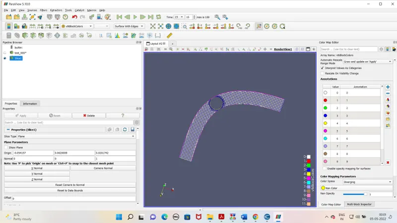
Mesh –
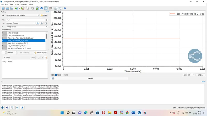
Pressure graph at inlet
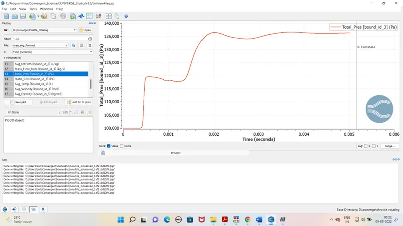
Pressure graph at oulet
velocity graph at inlet
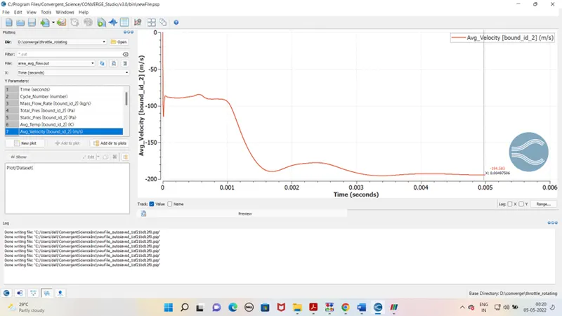
velocity graph at oulet
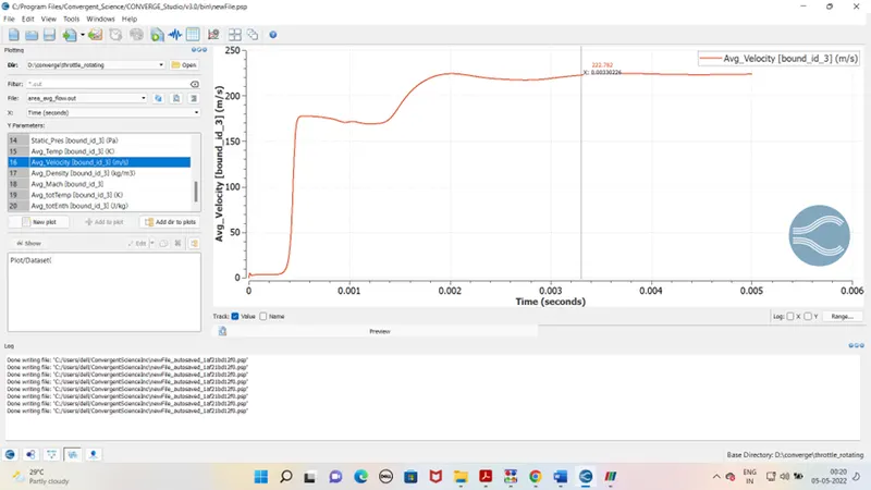
mass flow rate at inlet
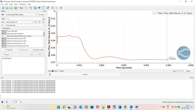
mass flow rate at oulet
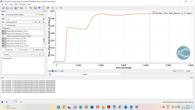
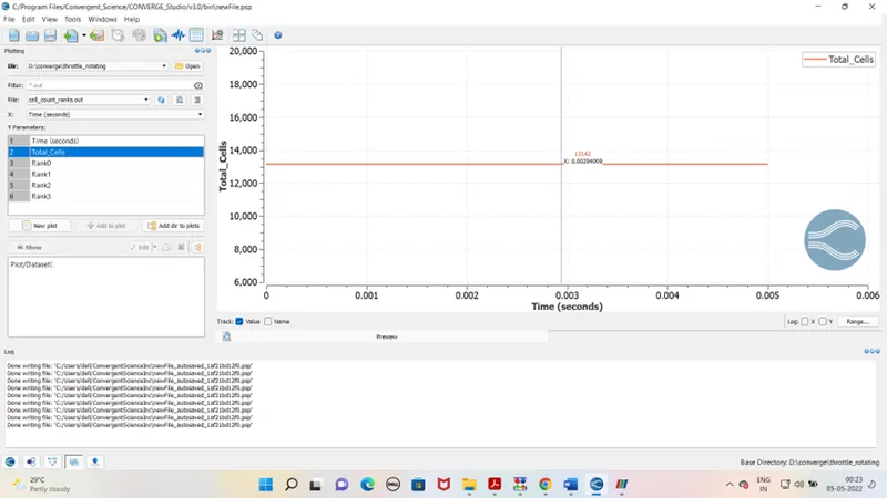
Total cells-
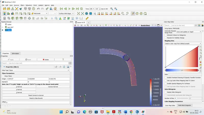
Pressure contour -
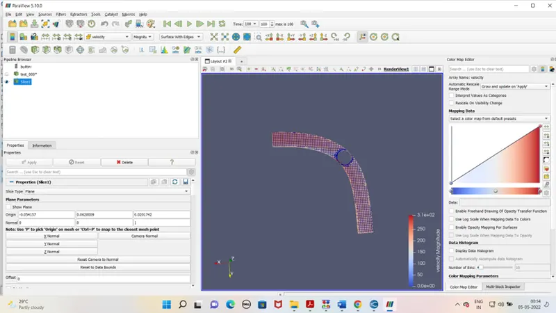
Velocity contour -
Conclusion -
It is noticed from contour graphs the velocity and pressure varies as throttle valve roates at defined interval.
Low pr. zone also cretaed near throttle valve.