Week 10: Project 1 - FULL HYDRO case set up (PFI)
Aim - This is full hydro PFI model in which we will be finding these following parameters -
- compression ratio of this engine
- Why do we need a wall heat transfer model? Why can't we predict the wall temperature from the CFD simulation?
- Combustion efficiency of this engine
- Determine the power and torque for this engine.
- What is the significance of ca10, ca50 and ca90?
Introduction-
In this project we go ahead with boundary flagging geometry created in non hydro case . In this we additional add the nozzle, spray parameters and combustion modelling for hydro PFI model .
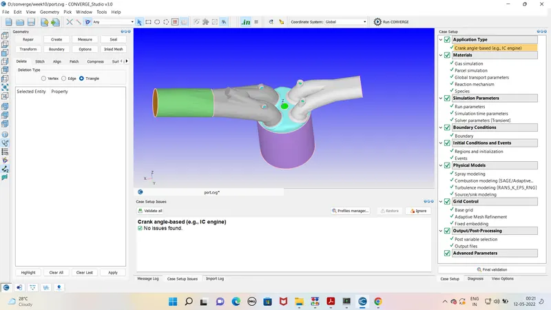
These are the following parameters for the engine case setup -
Engine parameters
Bore =0.086 m
Stroke = 0.09 m
Connecting rod length = 0.18 m
RPM = 3000
Run parameters
Simulation mode: No Hydro
Simulation time parameters
Start time : -520 deg
end time : 120 deg
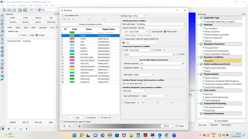
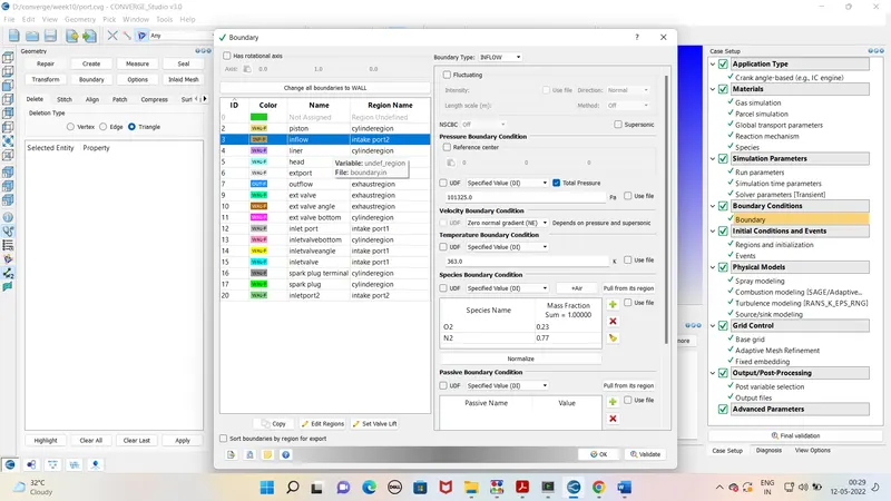
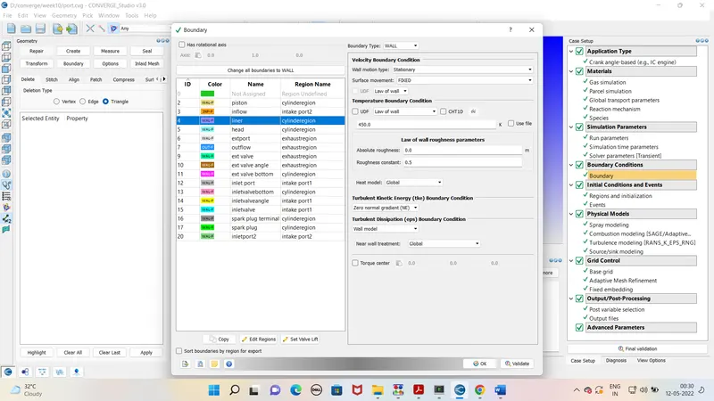
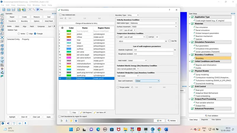
Boundary conditions
Piston
Inflow
Liner
Head
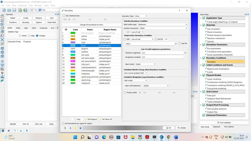
Ext port
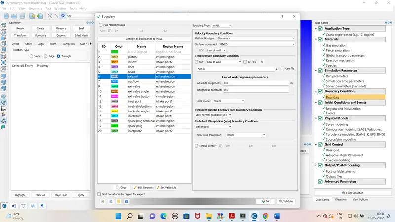
Outflow
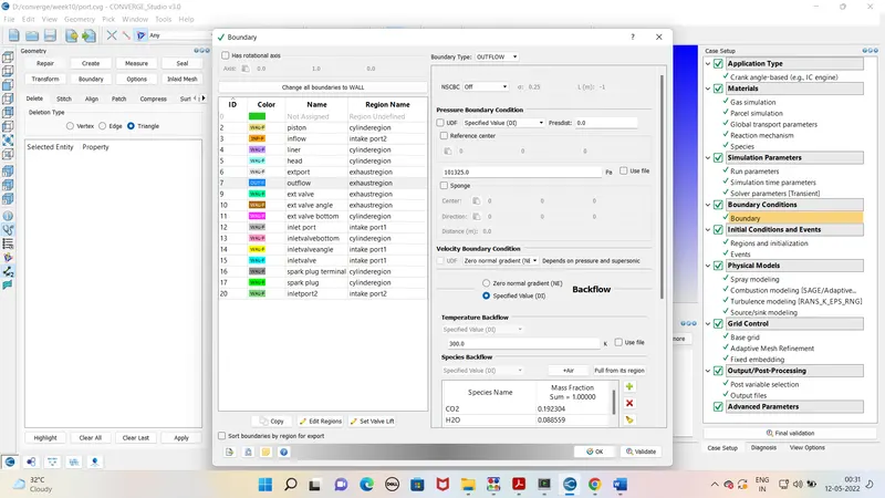
Ext valve top
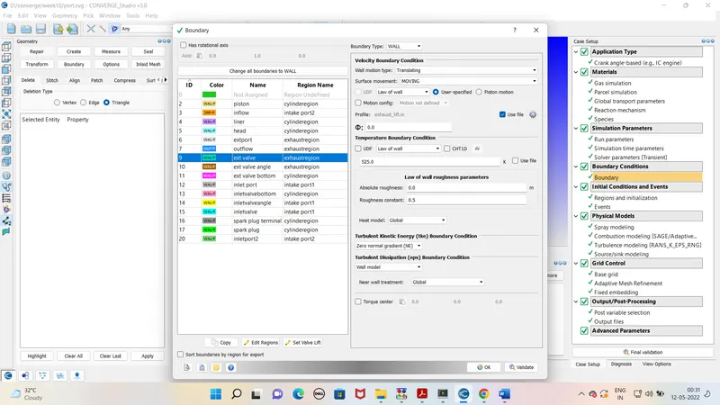
Ext valve angle boundary
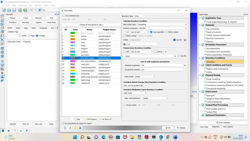
Ext valve bottom boundary
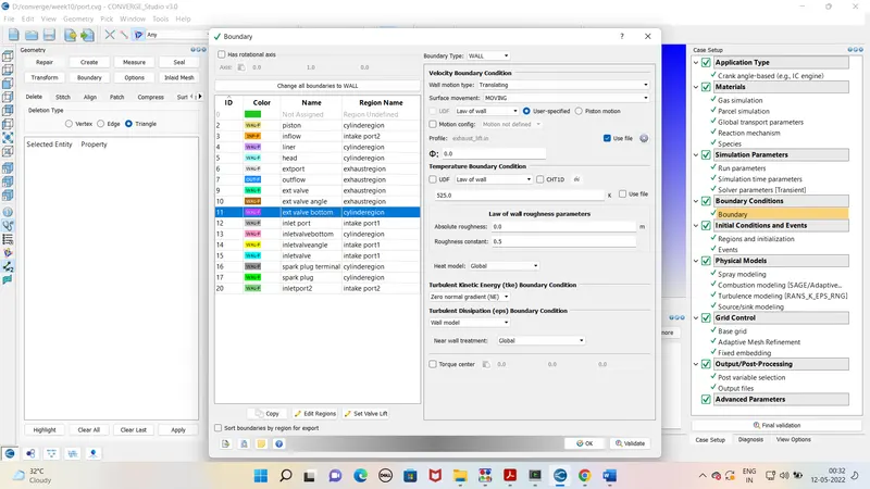
Inlet port
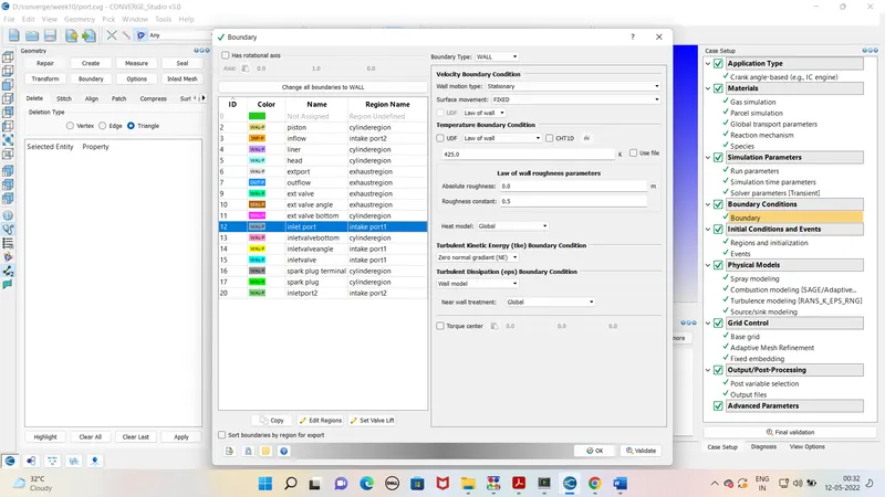
inlet valve bottom boundary
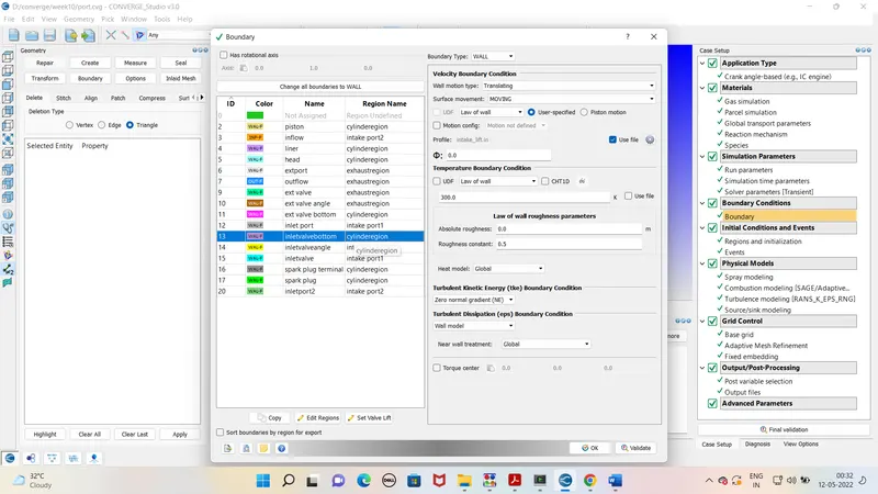
inlet valve angle boundary
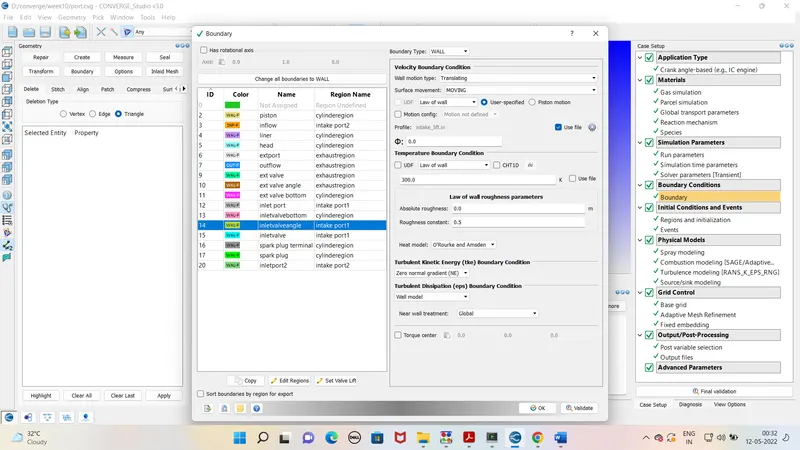
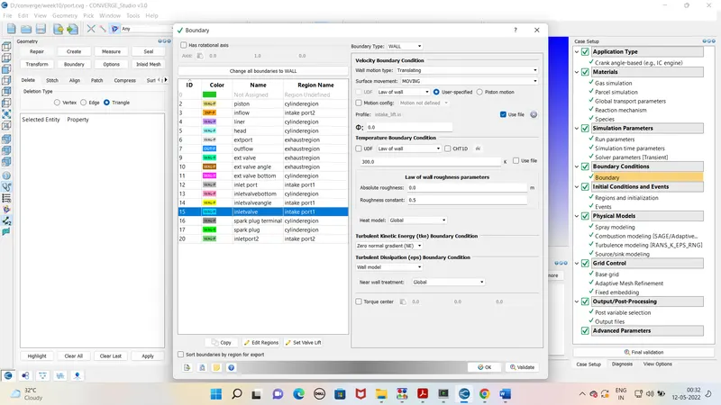
inlet valve top
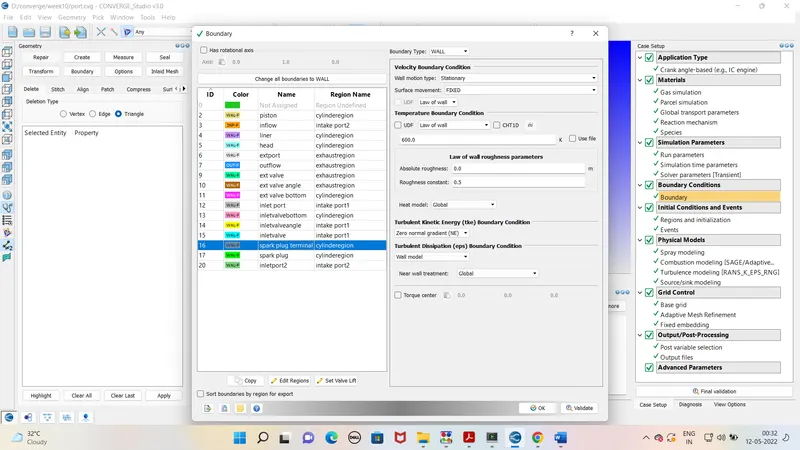
spark plug terminal
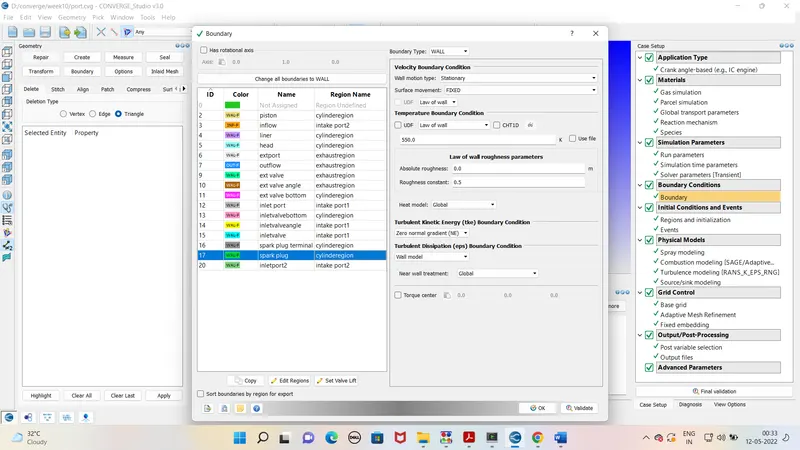
spark plug
inlet port2
Initial conditions
Intake port - 1 (closer to combustion chamber)
ic8h18 - 0.025508
o2 - 0.20157
n2 - 0.77292
Temperature - 390k
pressure - 1 bar
Intake port - 2 (away from combustion chamber)
Air
Temperature - 370K
Pressure - 1 bar
Cylinder
Pressure - 1.85731 bar
Temperature - 1360K
Stoichiometric composition
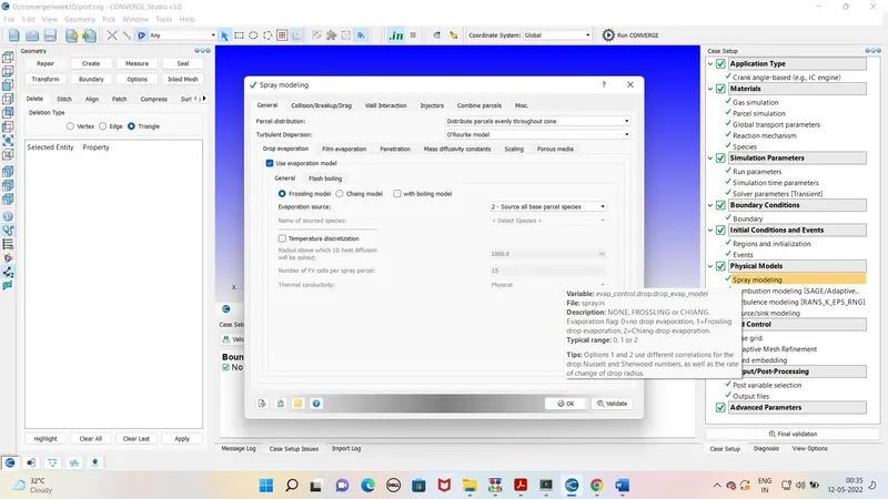
Spray modelling -
Select the model for the spray modelling as shown below . and add the injection parametrs and nozzel information as mentioned below.
Injection Parameters
Fuel flow rate = 7.5e-4 Kg/second
Injection start time = -480.0
Injection duration = 191.2
Fuel temperature = 330K
Nozzle positions
Nozzle diameter = 250 micro-meter
Circular injection radius = Nozzle radius
Spray cone angle = 10
Nozzle 0
center 0.0823357 0.00100001 0.07019
Align Vector -0.732501 0.210489 -0.647408
Nozzle 1
center 0.0823357 -0.00099999 0.07019
Align Vector -0.732501 -0.210489 -0.647408
Nozzle 2
center 0.0823357 -0.0004 0.07019
Align Vector -0.5 -0.2 -0.647408
Nozzle 3
center 0.0823357 0.0003 0.07019
Align Vector -0.5 0.2 -0.647408
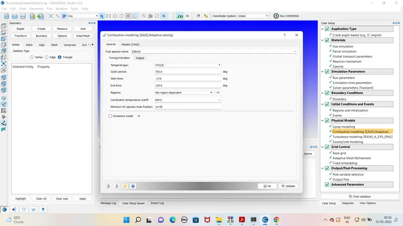
Combustion modelling -
Select the SAGE model for the combustion modelling. Select the species and put the data .
Spark Ignition Parameters -
Start of spark = -15 deg
Spark duration = 10 deg
Spark location = -0.003 0 0.0091
Spark radius = 0.0005m
Grid size -
Grid size is taken as 0.004.
AMR - AMR is done for the critical area for calculation purpose . In this case AMR is done for the velocity and temprature .
Fixed embedding -
Fixed embedding –
At critical area we used fixed embedding to refine the grid. In given geometry the fixed embedding is done for – Big cylinder embedding , small cylinder embedding, exhaust valve angle and inlet valve angle and injector .
After case set up exports the file to defined folder. Run the simulation in the Cygwin. Generate the output files. As output file is generated run the post processing in Cygwin again. Open the output file in paraview for the mesh view and simulation
Outputs –
PRESSURE Plot for the engine -
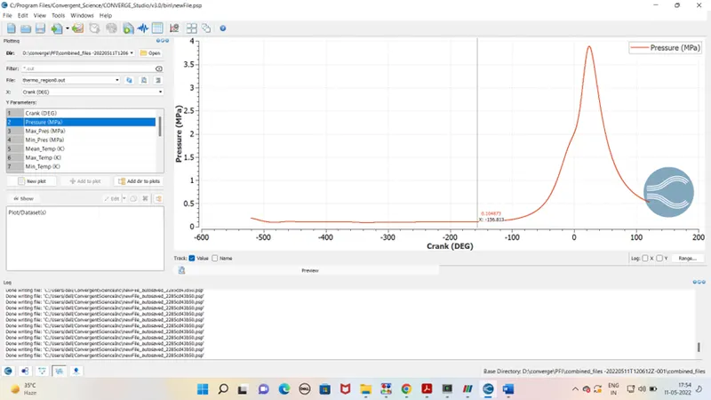
It is notice that pressure increases with burning of fuel, reach to maximum and drops after the combustion stroke.
Mean temperature plot cylinder -
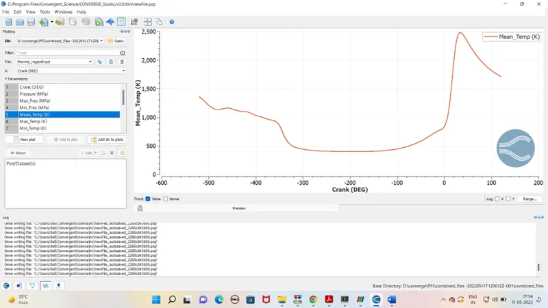
Temprature inside the cylinder is steady in starting due to the exhaust gases of last exhuast stroke and increases again rapidly as combustion take place inside the cylinder.
IHR Plot -
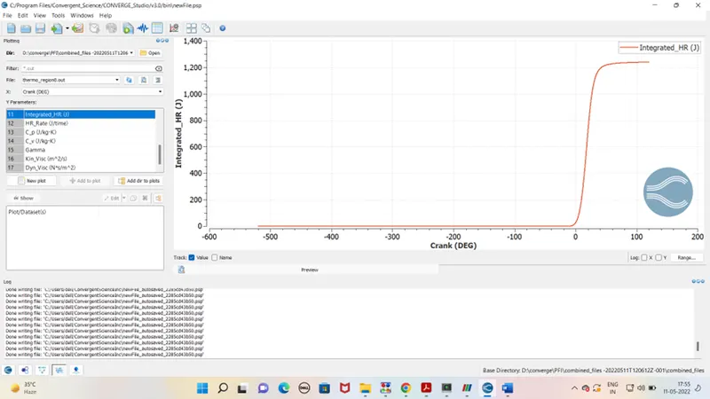
IHR basically tells the useful energy released in power stroke. and this energy is used for further cycles of engine and to get desired power output .
Heat release rate -
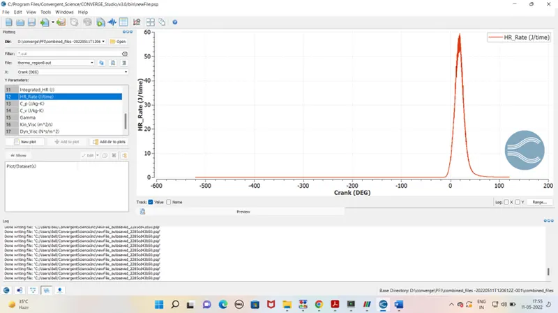
HRR define the hear release to surrounding . in starting it was near to minimal and increases during the power stroke.
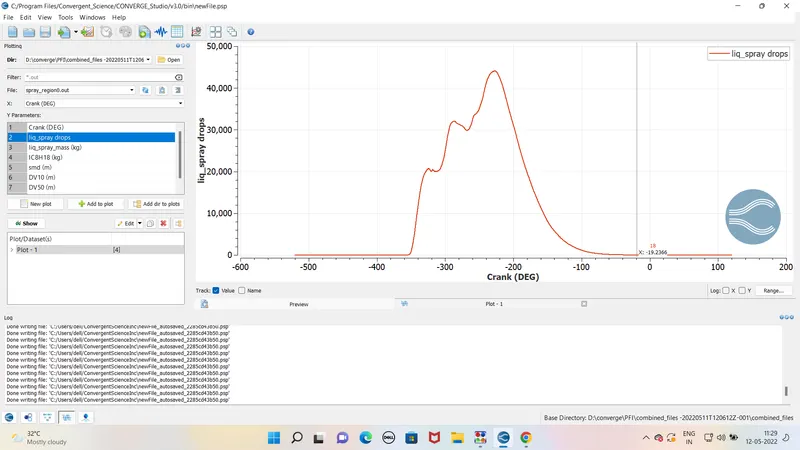
Liquid spray drop plot -
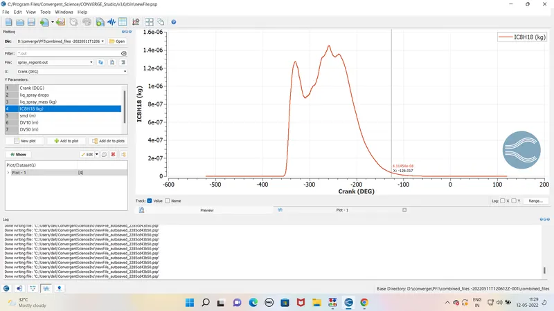
IC8H18 fuel Plot -
Emmision plot
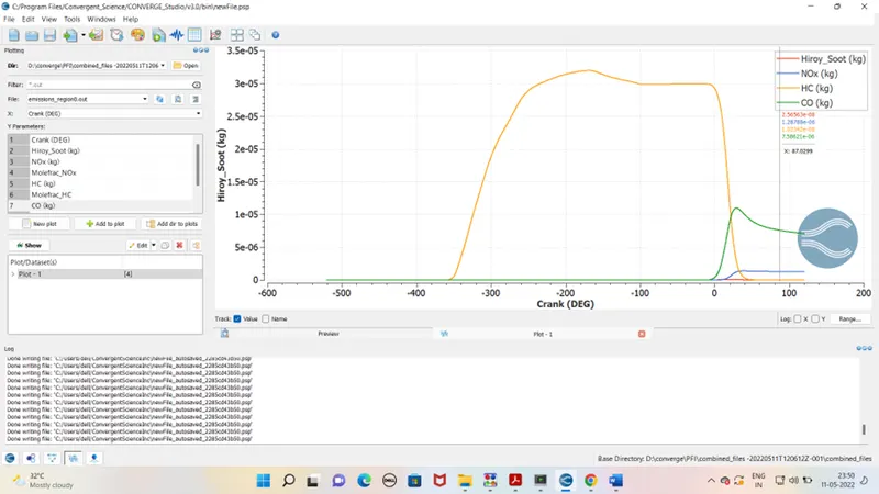
From emission plot indiaction are clear that HC content is high it may due to to rich mixture. On same hand the nox level is compartively low. HC can be control with TWC aftertreatment mehod.
- compression ratio of this engine
CR of engine is ratio of total volume to the clearance volume.
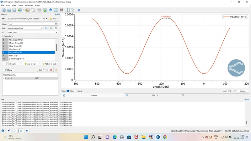
From volume graph we can calculate the CR.
Total volume – 5.74121 x 10 ^-4 m3
Clearance volume- 5.75786 x 10 ^-5 m3
CR- 5.74121 x 10 ^-4 / 5.75786 x 10 ^-5
CR- 9.971
- Why do we need a wall heat transfer model? Why can't we predict the wall temperature from the CFD simulation?
In CFD simulation the thermodynamic data for the parts of engine as input , so wall temperature cant be calculated . That’s why we require heat transfer model to predict the temperature of wall.
- Combustion efficiency of this engine
Mass of fuel – 0.000003 kg
Calorific value- 43.4 mj/kg
Integraed heat release for PFI is – 1241.04
Combustion efficiency = 1241.04/43.4 x 0.000003 x 1000000
= 95.31 %
- Determine the power and torque for this engine.
Work done – 468.646 NM
Duration- 240.199 degree
Crank speed – 3000
Degree / sec- 3000/60 X360 = 18000 DEG/SEC
Time for combustion – 240.199/18000 = .0133 sec
Power = W.D / Time = 468.646/ .0133 = 35.23 kw
Power = 2x PIE x N X T / 60
Torque = 35.23 x 1000 x 60 /2 x 3.14 x 3000
Torque – 112.19 N m
5. What is the significance of ca10, ca50 and ca90?
CA10 ,CA50 and CA90 basically tells the fuel combustion rate with respect to crangle .
CA 10 and CA50 shows the heat release 10% na 50 %repectively .
CA10 basically used in the study of start of iginition.CA50 indicates the end of premixed combustion and start of diffusion of fuel .
Conclusion –
For given enigne the HC content is high, we can also see from liquid spray as there some fuel is trapped which is remain unburnt. So to overcome we can increase the pressure of fuel for better atomization. Aftertrement mehtod like TWC can be install to overcome the HC level .