Week-6 : Turbocharger Modelling
Aim – To under stand the concept of T/C , its types and application. How we can operate it up to its optimum efficiency to achieve our desired results.
Task1 –
Turbocharger –
The turbocharger is an integral part of the engine as it reuses the exhaust gases in order to increase the overall efficiency of the engine. It consists of two parts – compressor and turbine sides.
Difference between Turbocharger and supercharger –
Supercharger is power boosting device which requires engine power run the compressor. But Turbocharger use the exhaust gas kinetic energy to run the turbine which is coupled to compressor. its show T/C doesn’t require any source for running.
Types of turbocharging system
- Constant Pressure Turbocharging system
- Exhaust gas from all cylinders into a common large manifold where pulse energy is largely
- The gas flow will steady rather than intermittentand at a constant pressure at turbine inlet.
- Pulse turbocharging System
- To prevent this, cylinders are grouped relatively with connections to two or more exhaust pipes
- Pipes are arranged, in small diameter to boost up pressure pulse and in short, straight length to prevent energy loss
- Number of exhaust branch depends upon firing order, number of cylinders and turbocharger design
Note – In slow speed engine constant Pr t/c system is beneficial on other hand for high speed engines Grouping of exhaust pipes gives good result.
Types of turbocharger-
- Single-Turbo
- Twin-Turbo
- Twin-Scroll Turbo
- Variable Geometry Turbo
- Variable Twin Scroll Turbo
- Electric Turbo
.
Important terms in T/C -
Turbo Lag
The lag comes from the time it takes the engine to create enough exhaust pressure to spin the turbo and pump compressed intake air into the engine in starting.
Turbocharger Surging
When output pressure of compressor or turbocharger falls below inlet manifold pressure due to any reasons (reasons may be exhaust gas temperature, engine rpm etc.) then there is reverse flow of pressurized air. Pressurized air flows in backward direction i.e., from scavenge manifold to turbocharger i.e., into compressor and filter. It causes vibration and sounds from compressor vanes.
Task 2 Explore tutorial number 6 ,7
I have considered three cases for analysis of turbocharger operations.
Case 1 – Without T/C
Case 2 – Only compressor (Supercharger)
Case 3 – Complete T/C assembly.
After executing the simulation for the all cases at same rpm. The results which cover important aspects are listed below.
|
Particulars |
case1 |
case2 |
case3 |
|
Brake Power [kW] |
217.7 |
226.2 |
220.9 |
|
Brake Torque [N-m] |
577.6 |
600 |
585.8 |
|
Air Flow Rate [kg/h] |
1093.3 |
1550.3 |
1565.7 |
|
Fuel Flow Rate [kg/h] |
51.8 |
51.8 |
51.8 |
|
BSFC [g/kW-h] |
238.1 |
229.2 |
234.7 |
|
Volumetric Efficiency [%] |
185.4 |
262.9 |
265.5 |
|
A/F Ratio |
21.09 |
29.91 |
30.2 |
|
NOx in ppm |
1143.49 |
1467.8 |
1474.06 |
|
HC in ppm |
0.07 |
0.05 |
0.05 |
Observations –
- case 1 vs case 2 as we installed compressor in case 2 the torque is increased because air quantity is inc for the combustion. Which resulted in good combustion and gives better bsfc. But same time NOX level increased as air is more available but HC level reduces.
- Case 2 vs Case 3 as we now coupled the turbine with compressor no more we need to run the compressor with out source as we doing in case 2. It is noticed that A/F , Air flow rate almost are on same level. But there is little drop in power as is coupled with turbine . so in engine starting there is some lag and some frictional losses are always there.
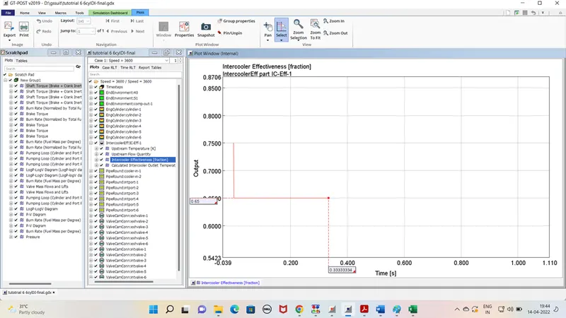
- As we installed the Intercooler . its purpose is to inc the air density and reduces its temperature . so more air can be admitted inside cyl. For the combustion.
- effectiveness was high in starting at admitting of fluid but it reach to steady state(.65) once flow normalised. As shown in figure.
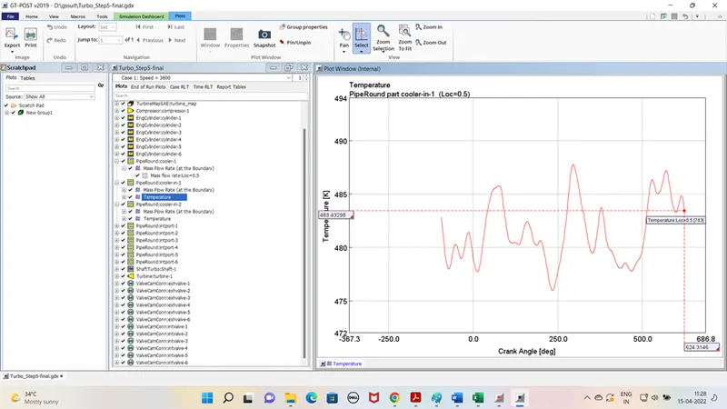
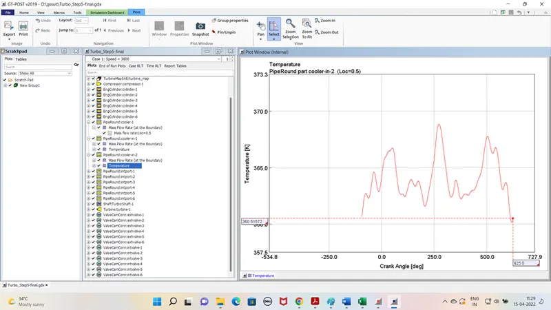
- Cooler inlet and oulet temp variation is shown in below figures.
Cooler in temp variation
Cooler out temp variation
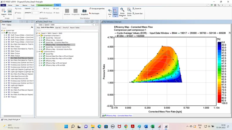
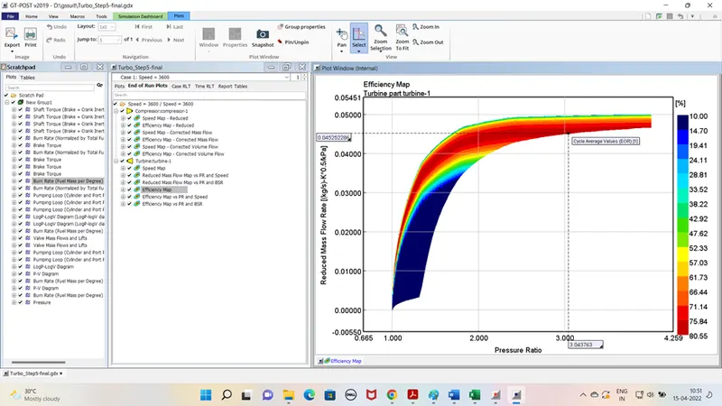
- Compreesor and turbine map
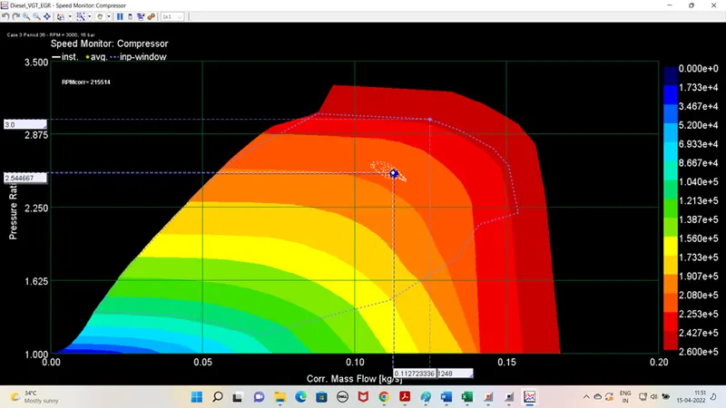
It is noticed that the avg point of compressor is located on higher rpm side which is risky and if its shifted to left it may lead to surging as well.
VGT Turbocharger case study –
1.In VGT Aerodynamically-shaped vanes in the turbine housing at the turbine inlet are fitted. these vanes rotate to vary the gas swirl angle and the cross-sectional area. At low RPM, a low A/R ratio allows the turbo to quickly spool up by increasing exhaust gas velocity and. At higher RPM the A/R ratio increases, therefore by allowing increased airflow. This provides wide range of torque at different rpm which is not possible with FGT. Eg- Normally vgt is limited to high Speed cars as its cost is also high. Low high torque application is not required to put vgt. FGT can play role in that case.
2.In the VGT example of GT SUITE the system comprise the VGT controller which regulate the vanes movement according to the the pressure ratio at the intake manifold.
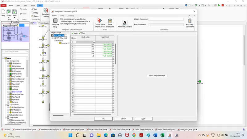
3.I have run the simulation for the 3 cases . The rack position is defined for different position and shown in figure.
Observations –
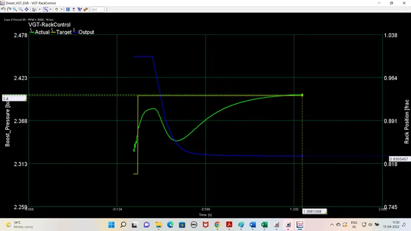
- If we take the case 3 scenario rack was in fully open condition to allow max exhaust vol on turbine side which resulted inc the A/F ratio . after attaining the steady state rack move to its minimum opening as shown in figure.
- Compressor map readings are reflected in the figure shown below.
Conclusion- As its clearly indicated that the installation of t/c is to be done after considering all aspects like its operating conditions , applications etc.