Week 6 - CHT Analysis on a Graphics card
Aim - Perform a steady-state conjugate heat transfer analysis on a model of a graphics card.
Introduction –
Graphic card basically used in computer for the better picture quality. As we see the computer with high graphics defiently deploys graphic system of high voltage, which will give rise to the high heat generation as well. So it is necessary to do study of heat generation and its effect as well .
Procedure –
Geometry –
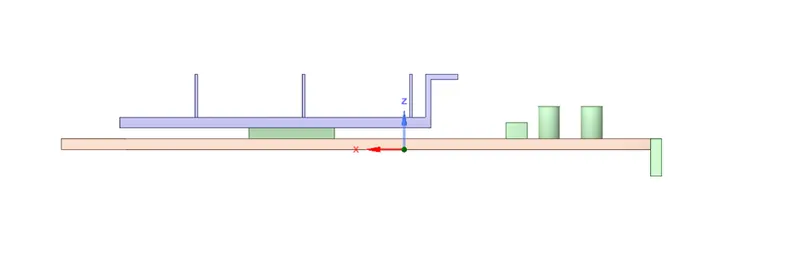
Load geometry in space claim. Share topology to be set at the share for accruate meshing.
Meshing –
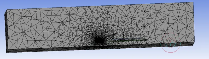
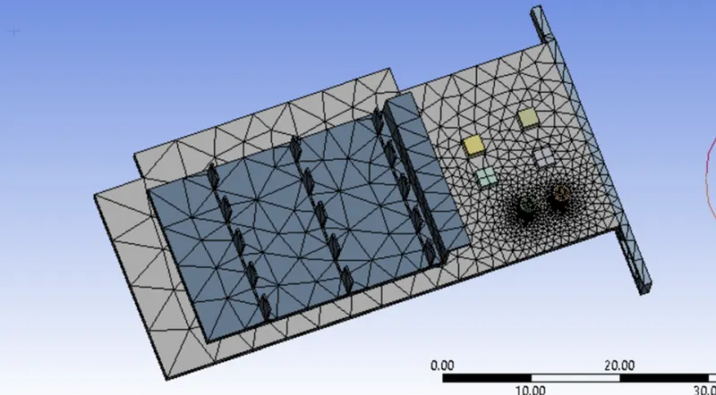
Generate the mesh with base size 10 mm .
Elements - 83008
Fluent steup –
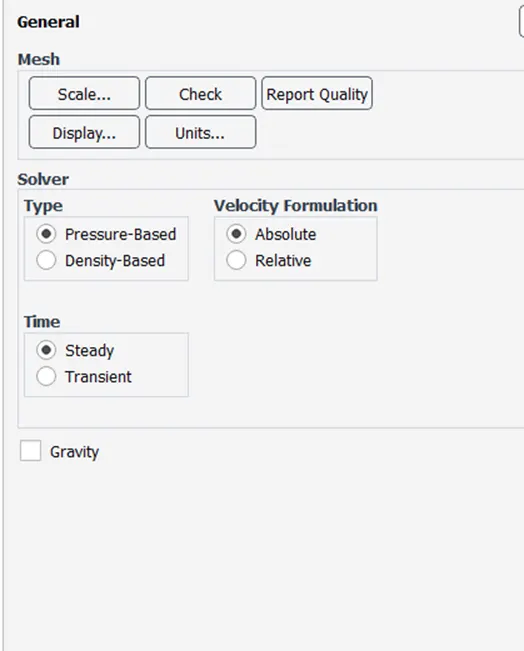
Solver Type - Pressure based
velocity formation – Absolute
Time – Steady
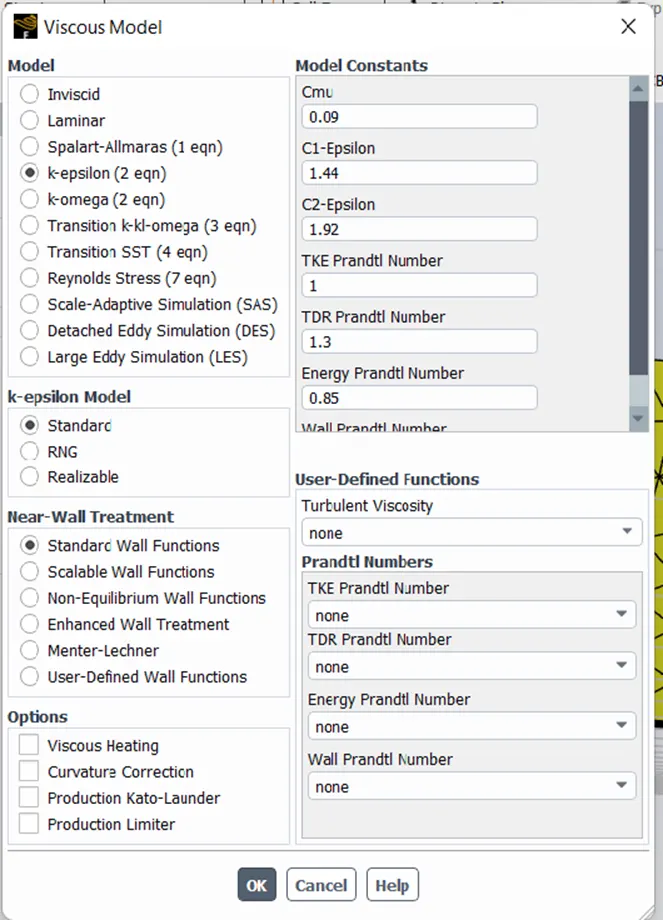
Model
K-Epsilon standard
Material –
Fluid - Air
Solid – 1. Aluminium for Fins
- Silicon For Processor
Density – 2000 kg / m^3
Specific Heat - 710 j/kgk
Thermal conductivity – 150 w /mk
- Insulator for base
Density – 1850 kg / m^3
Specific Heat - 950 j/kgk
Thermal conductivity – 0.29 w /mk
Cell zone –
Processor – Silicon
Type – solid
Power consumption is assumed as 85w, volume of processor is 64 mm^3
So the Heat generated /volume = 131250000w/m3
Base and Fins = type - Solid
Boundary Condition -
Inlet velocity – 1 m/s for case 1, 3 m/s for case 2, 5 m/s for case 3.
Outlet – Type – Pressure outlet
Wall – Symmetry walls
Definition –Velocity Plot, Coefficient of drag and lift plot .
Initialization – Hybrid
Results -
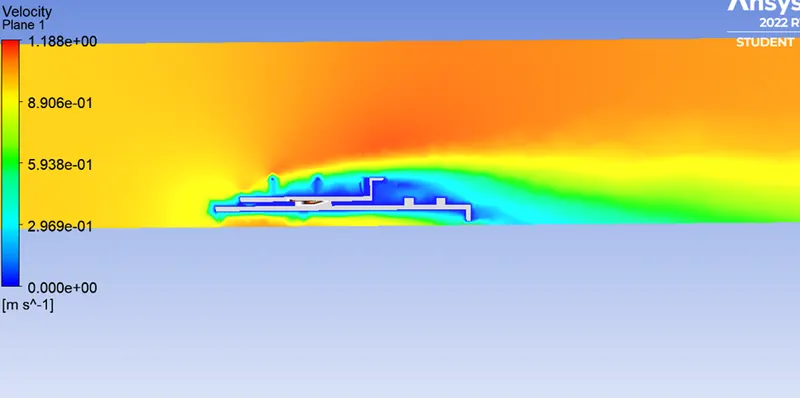
Case 1 - 1 m/sec
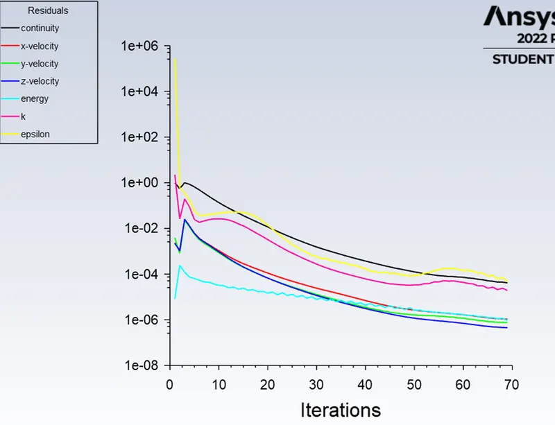
Residual plot -
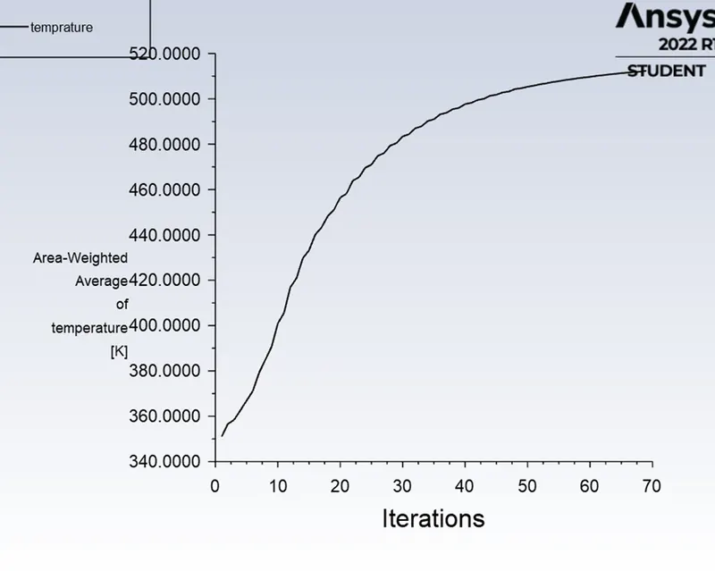
Average temprature graph -
Velocity contour -
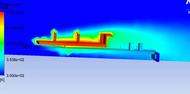
Temprature contour –
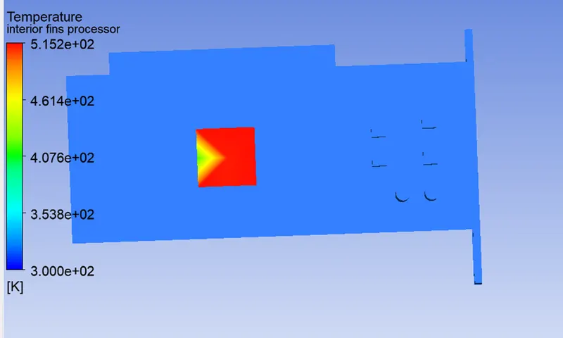
Temprature contour for processor body –
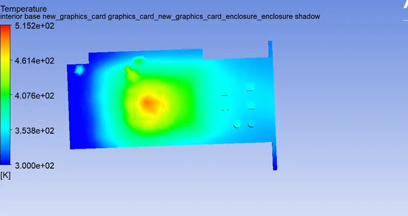
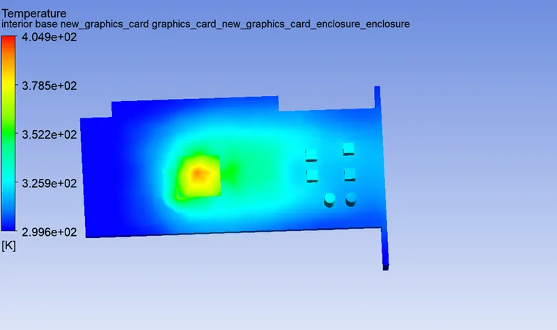
Temprature contour for base –
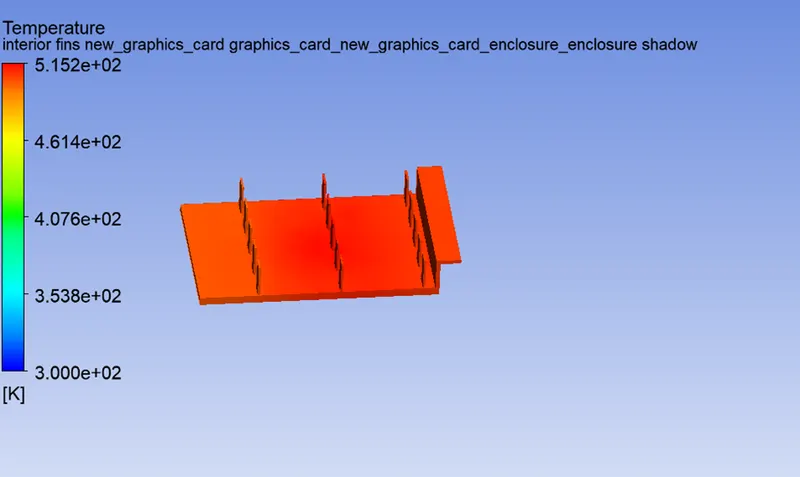
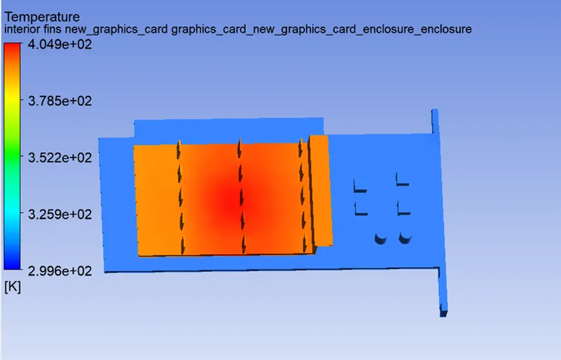
Global Temprature contour for fin body –
Case 2 - Inlet velocity - 3 m/sec
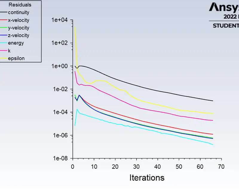
Residual plot -
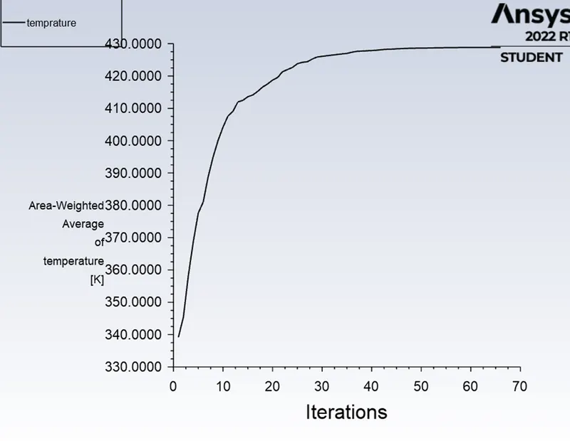
Average temprature graph -
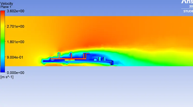
Velocity contour -
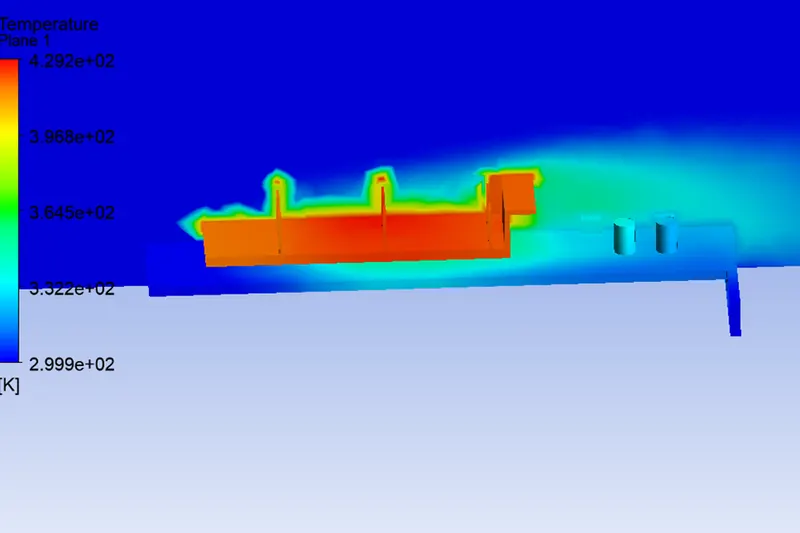
Temprature contour –
Temprature contour for processor body –
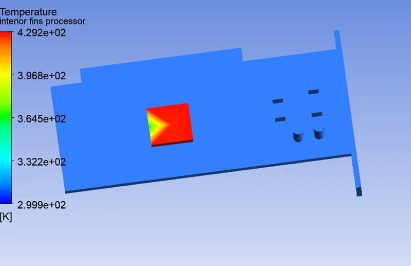
Temprature contour for base –
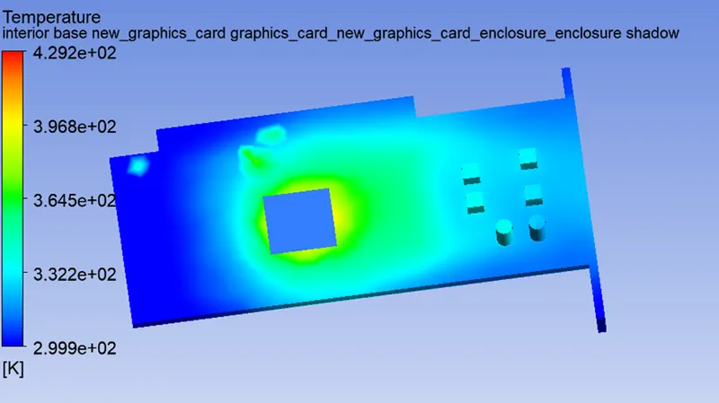
Global Temprature contour for fin body –
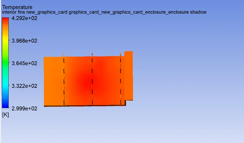
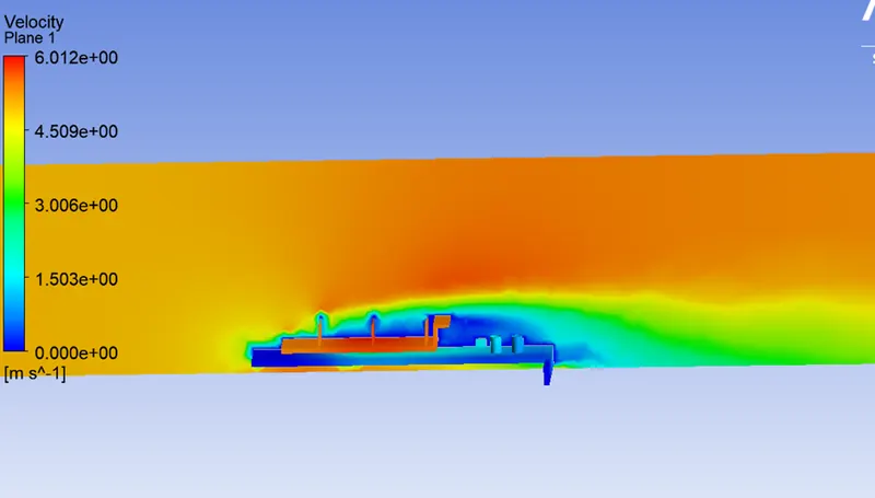
Case 3- Inlet velocity - 5m/s
Residual plot -
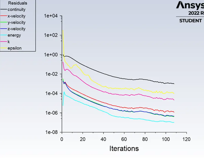
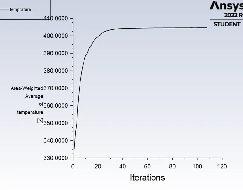
Average temprature graph -
Velocity contour -
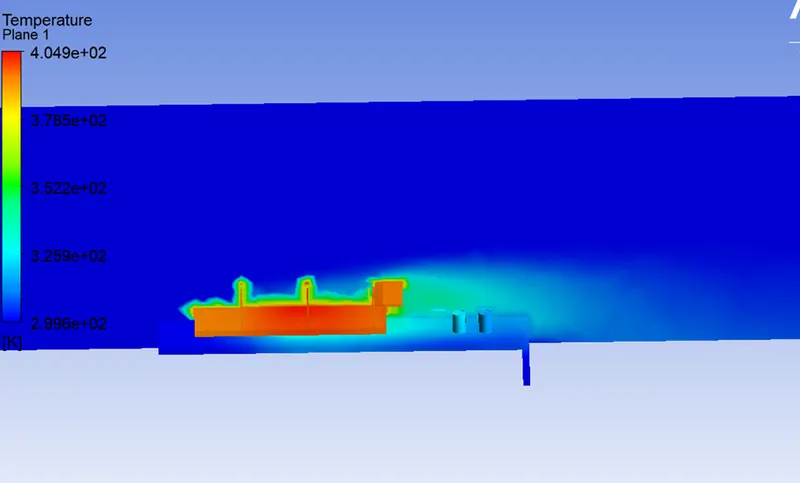
Temprature contour –
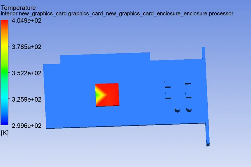
Temprature contour for processor body –
Temprature contour for base –
Global Temprature contour for fin body –
Conclusion -
Average Temprature
Case 1 - 515.2 k
Case 2 - 429.2
Case 3 - 404.9 k
1. As we have seen with increase in velocity of air at inlet reluts the drop in average temprature .
2. The hotspot bascially generated near to the processor .
3.The high temprature can be overcome by increasing the inlet velocity.
Remarks -
1. Solution is getting converge quite early .
2. Uable to calculate heat transfer coffcient due to error showing while exporting cdat file from fluent.