Week 6: Conjugate Heat Transfer Simulation
Aim- To study the flow through pipe to understand the phenomena of conjugate heat transfer. And concept of super cycling .
Introduction –
CHT- When ever heat is transfer from fluid to solid region or from solid to fluid region through the interface the conjugate heat transfer comes in picture. Heat transfer in solid take place through conduction. where as in liquid heat transfer is done through convection.
Super cycling –
Heat transfer rate in the solid is bit slower than the fluid. Due to which the solid region takes more time to get converge / to reach steady state. In this condition super cycling concept is applied.
Steps –
- Import the geometry in converge software.
- Define the boundary.
- Case setup
- Simulation
- Post processing
- Output
Case setup –
Application type –
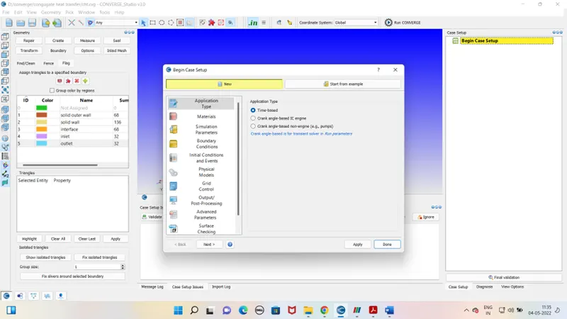
Pre defined mixture - Air
Gas simulation –
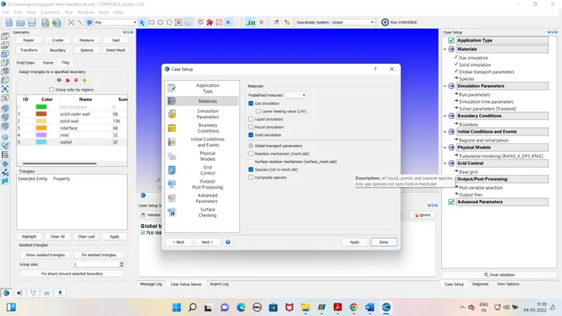
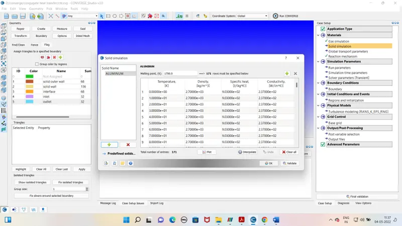
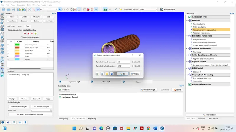
Global transport parameter – Default
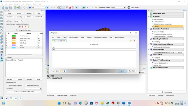
Species-
Simulation Parameter –
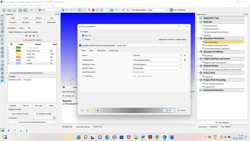
Run parameter –
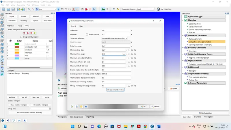
Simulation time parameters-
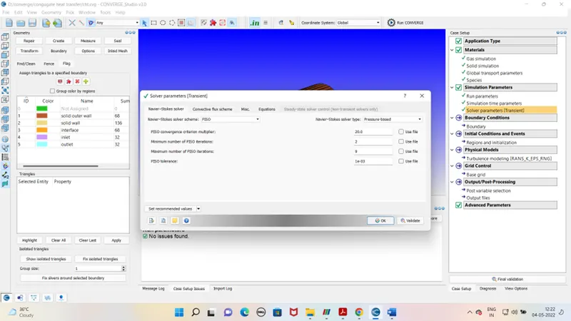
Solver parameters-
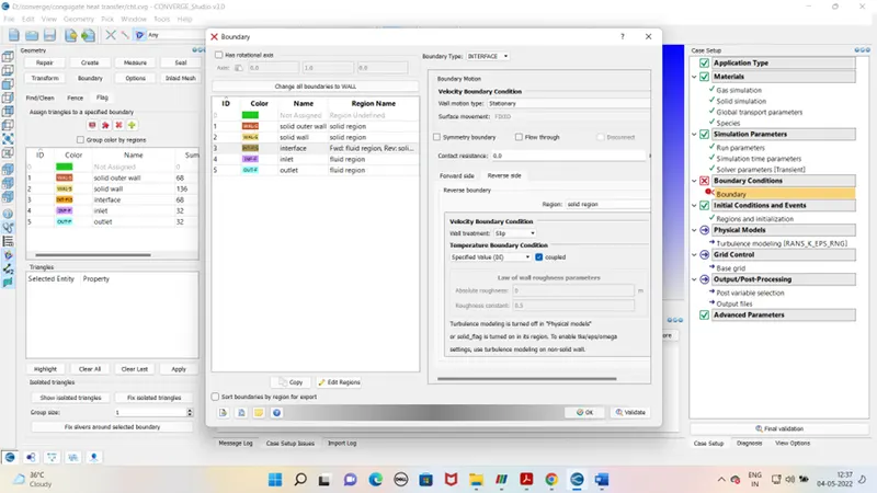
Boundary condition –
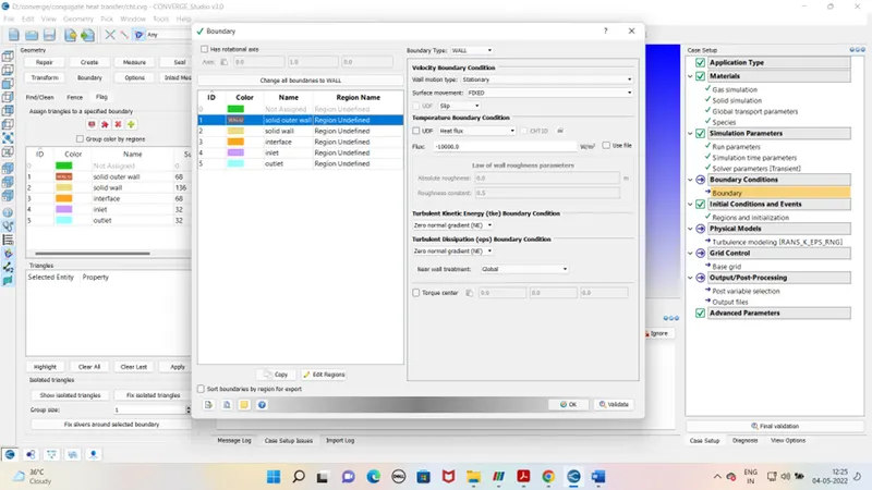
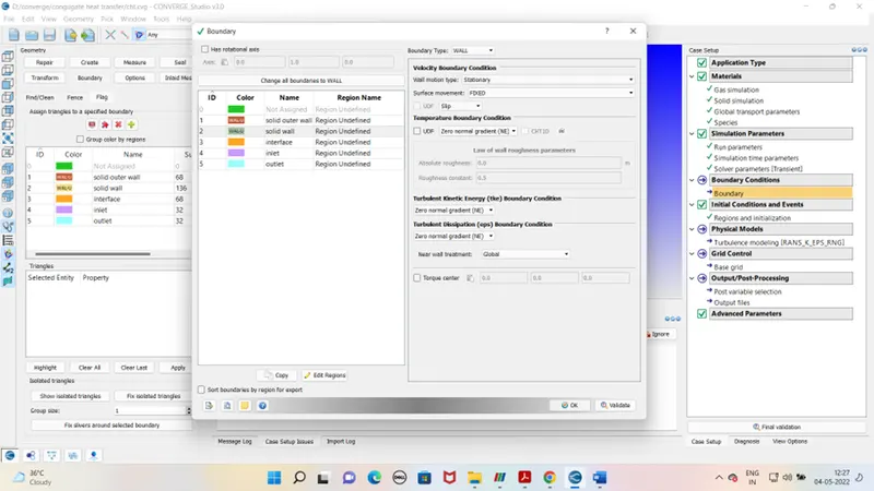
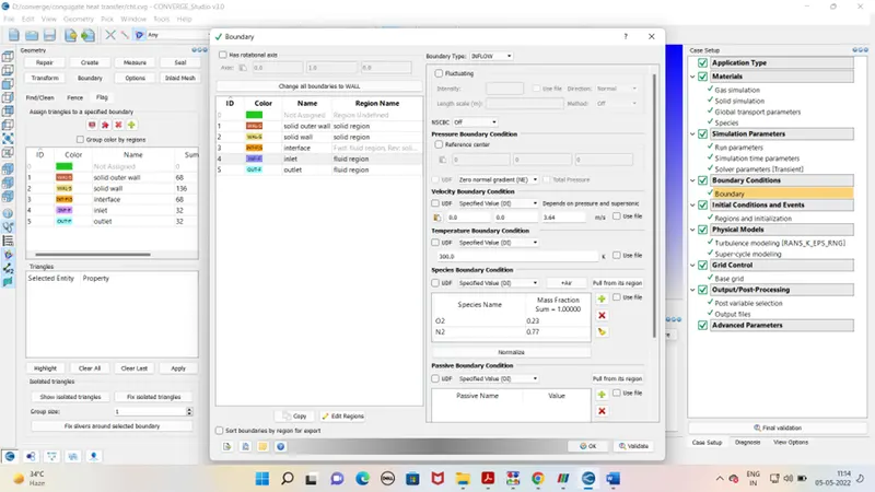
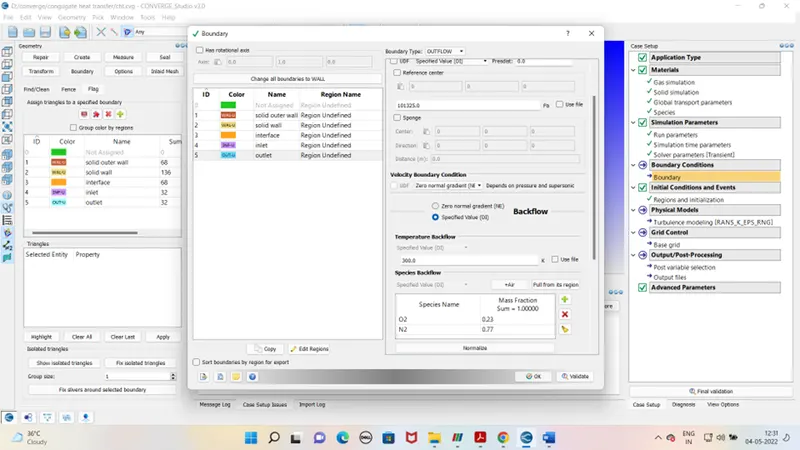
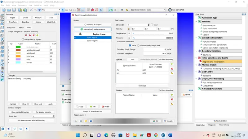
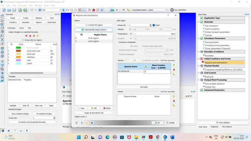
Intial condition and events –
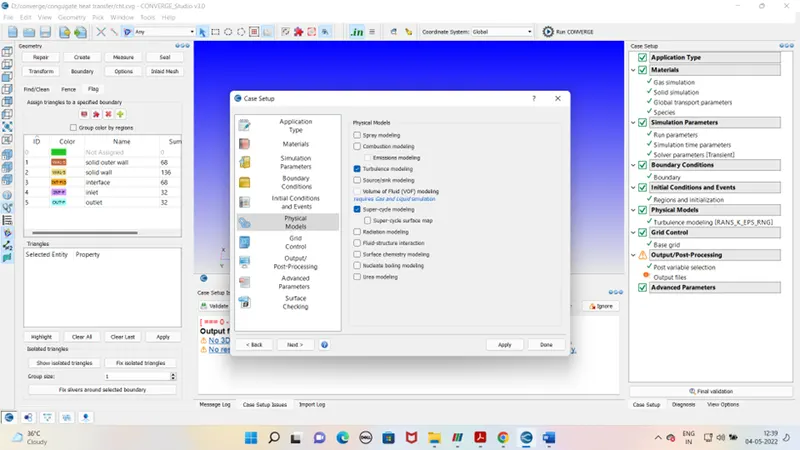
Physical models –
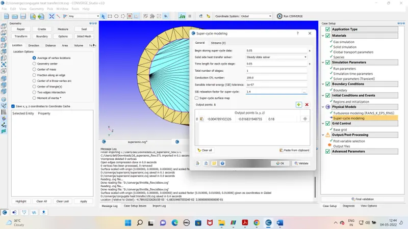
Grid control –
Base grid – dx - 0.004
dy – 0.004
dz – 0.004
Output processing Advanced parameter -
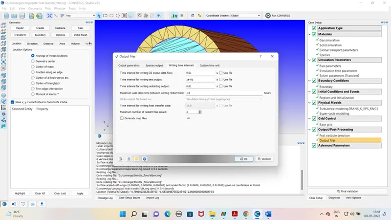
After case set up exports the file to defined folder. Run the simulation in the Cygwin. Generate the output files. As output file is generated run the post processing in Cygwin again. Open the output file in paraview for the mesh view and contours. For excessing pressure , velocity and mass flow rate use line plotting tab.
Outputs –
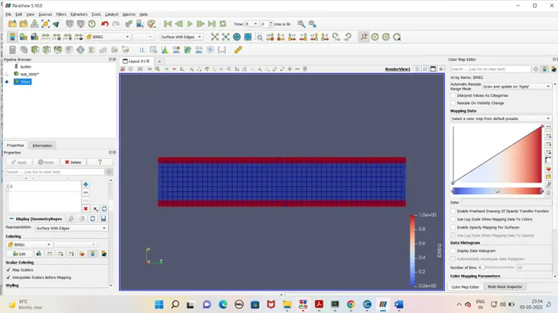
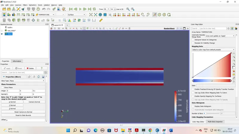
For grid size – 0.004 , supercycling time – 0.05
Mesh -
Temperature contour –
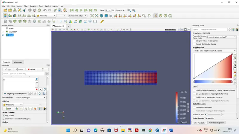
Pressure contour -
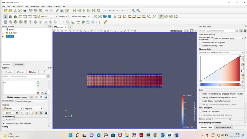
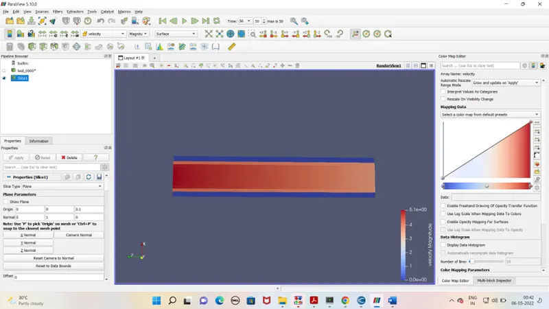
Velocity contour-
For grid size - .003 , supercycling time – 0.05
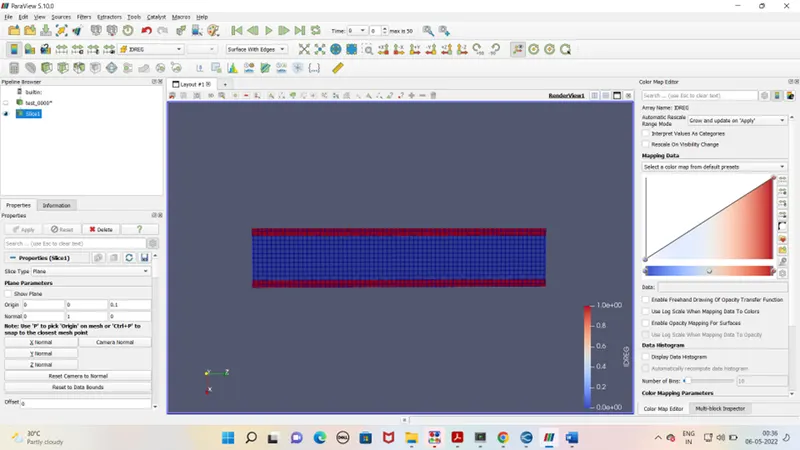
Mesh
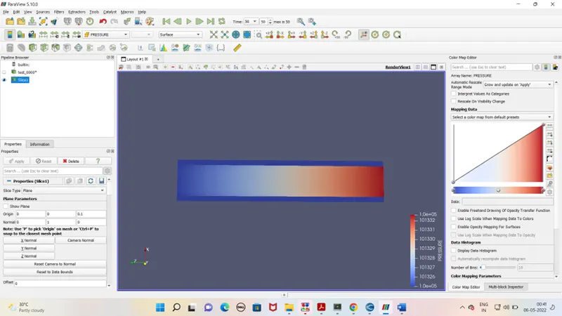
Pressure contour -
Velocity contour -
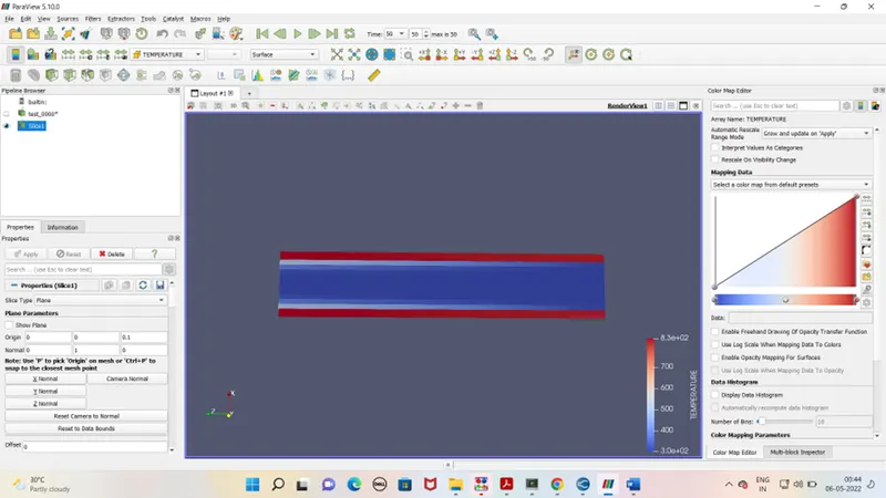
Temperature contour –
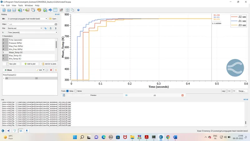
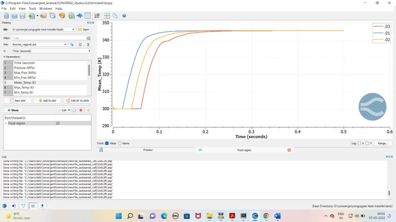
Supercyclic results for time interval 0.01 , 0.02 , 0.03 –
Temp graph for solid region
Temp graph for fluid region
Conclusion –
It is clear from graphs when we reduce the super cycling time the solver reach to steady state early and gets converge .