Week-7 : Converting a detailed engine model to a FRM model
Aim- To study the concept of FRM. Building of the model with FRM builder approach. And its study.
Task 1 - Build FRM Model
Engine configuration is given as follow -
Bore - 102 mm
stroke - 115 mm
CR -17
No of cylinder - 6nos
CI engine
Turbocharge - Twin Scroll Turbine
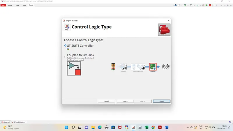
Controller logic type - GT Controller
Step 1 – Go to Tool bar click on FRM builder. Click on new engine model.
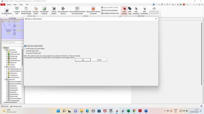
Step 2 – select engine type CI confriguration
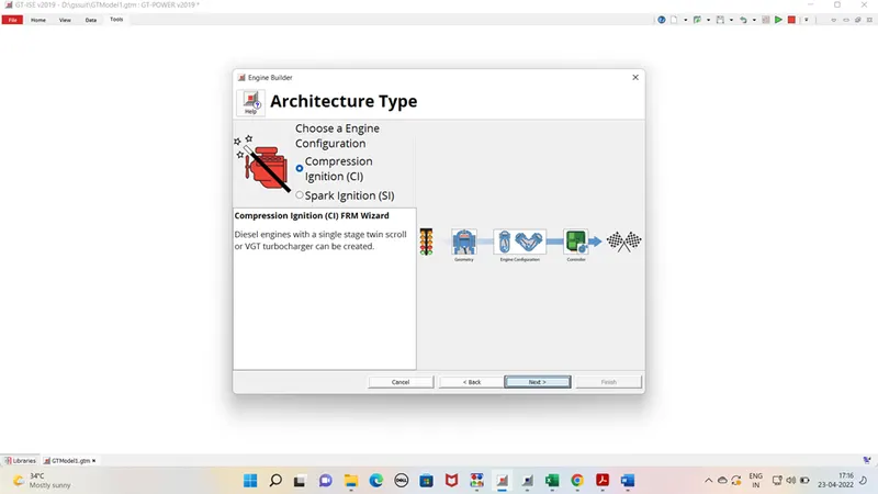
Step 3 – Add cylinder geometry as per given data
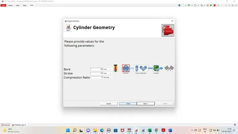
Step 4 choose turbo type as twin scroll
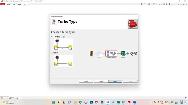
Step5 – choose engine type 6 cylinder
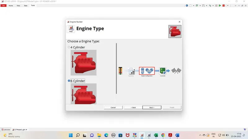
Step 6 - choose Gt suite controller and click on finish.
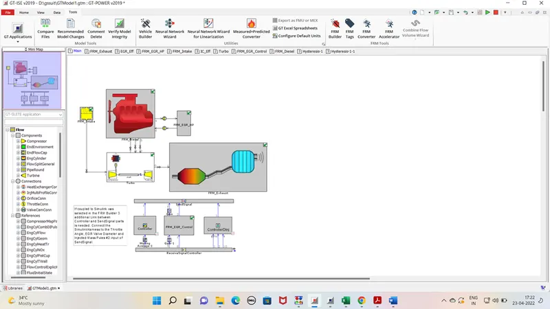
Step 7 – Final model is shown below.
Model description –
- It is 6 cylinders, 4 stroke CI engine. It is having twin scroll Waste gate type turbocharger, which means turbine is having two inlets for exhaust gases. And waste gate will control the exhaust gases entry to turbine inlet as per requirement.
- For emission control engine is having EGR arrangement. Which redirect the exhaust gases to the inlet manifold as per target parameters.
- FRM approach helps in simple designing of the engine. It is shown the inlet and exhaust having single manifold as compare to details modelling. This will reduce the time of simulation.
Controller in model –
- Waste gate controller – It depends on the boost pressure of inlet manifold. According to that it bypasses the exhaust gases at turbine inlet.
- FRM EGR controller – EGR controller is dependent of the EGR map . according to defined map inputs the EGR percentage is controlled in the intake manifold.
- Direct injection controller- DI injection is depended on the desired BP output. According to required bp injection rate is decided.
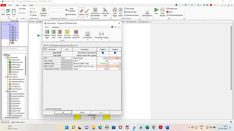
Case set up for model is as follow-
Simulation results –
|
case 1 |
case 2 |
|
|
Brake Power [kW] |
303.6 |
329.9 |
|
Brake Torque [N-m] |
724.7 |
900 |
|
Air Flow Rate [kg/h] |
1370.5 |
1333.4 |
|
BSFC [g/kW-h] |
258 |
231 |
|
A/F Ratio |
17.5 |
17.5 |
- In case2 our target was to achieve BMEP 22 . Which resulted in higher power in the case 2 as compare to case 1.
- Bsfc also is reduced in case2 as Fuel injection is advanced as compare to case 1.
NOx emission are as follow-
|
cylinder 1 |
cylinder 2 |
cylinder 3 |
cylinder 4 |
cylinder 5 |
cylinder 6 |
||
|
NOx in ppm |
case 1 |
61.44 |
0 |
0 |
0 |
0 |
0 |
|
case 2 |
175.32 |
0 |
0 |
0 |
0 |
0 |
EGR %age for Both cases is as follow –
|
cylinder 1 |
cylinder 2 |
cylinder 3 |
cylinder 4 |
cylinder 5 |
cylinder 6 |
||
|
EGR [%] |
case 1 |
0 |
0.1 |
0.1 |
0 |
0.2 |
0.1 |
|
case 2 |
0 |
0 |
0 |
0.1 |
0 |
0 |
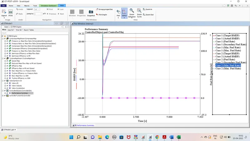
Fuel injection rate graph –
It is shown to achieve high bmep fuel injection rate also increased.
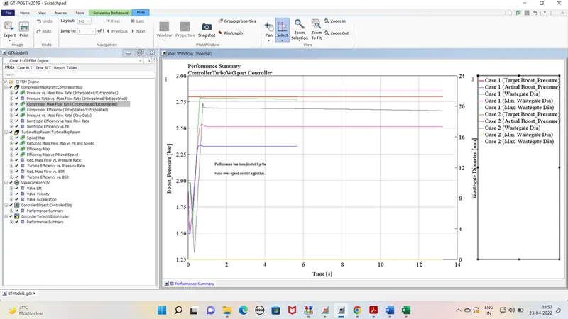
Waste gate controller graph –
Initial gate was at minimum positon to achive the desired boost pr. Gate is opened . Boost pr for case2 is higher then case 1.
Compressor map –
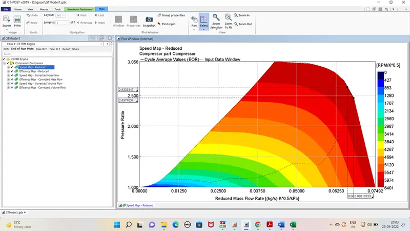
For both cases point are in chock zone which is not acceptable.
Task 2 - Explore tutorial number 9
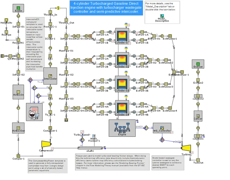
Basic model –
The model is basically
- 4-cylinder gasoline engine
- having waste gate turbocharger with waste gate t/c controller.
- The model having intercooler with intercooler efficiency monitor.
- Injection type – Direct injection system
- Each cylinder is having two inlet port and exhaust port. Both having individual pipeline for that.
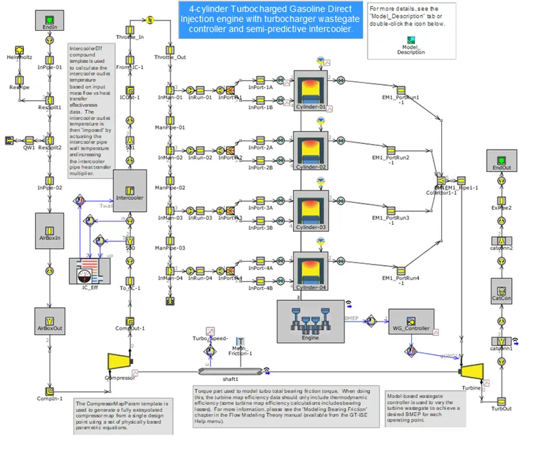
FRM Case 1-
In this case exhaust from each cylinder is driven to single exhaust manifold through runner from each cylinder.
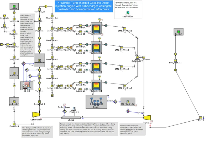
FRM Case 2-
After treatment device is simplified after turbine outlet.
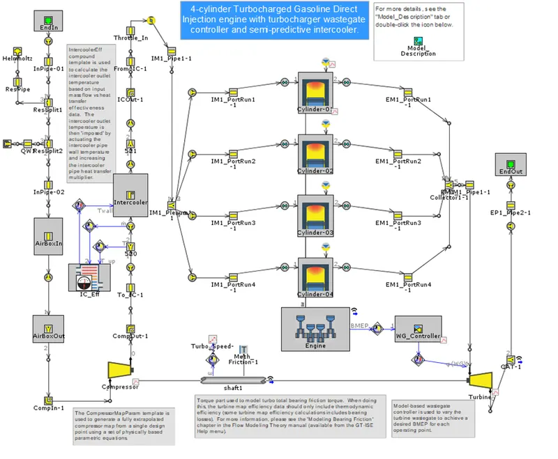
FRM Case 3 –
Same like exhaust inlet port is merged to form single manifold, from that runner is provided to each unit.
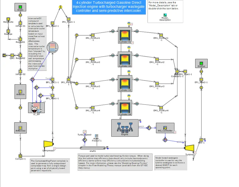
FRM Case 4-
In this case compressor outlet pipes are simplified.
FRM Case 5
Air Inlet arrangement to the compressor side is simplified.
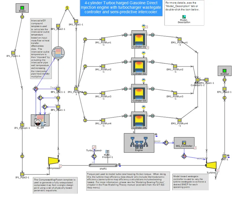
FRM Case 6
Exhaust from manifold is directly transferred to the turbine inlet instead of entering separate pipe as shown in FRM case 5 after exhaust manifold.
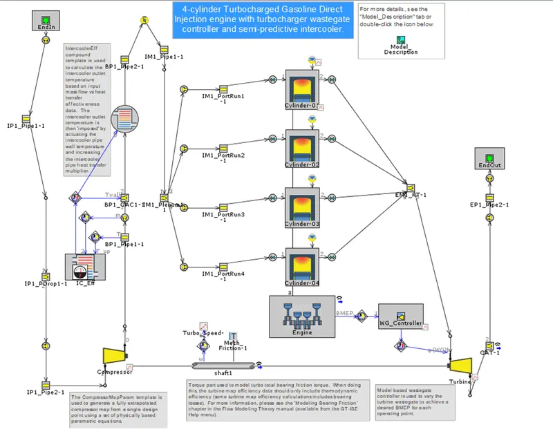
FRM Case 7
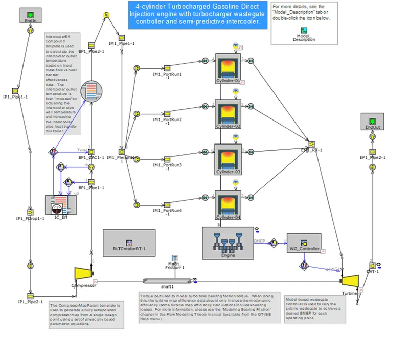
Cylinder slaving operation in done. in which cylinder 1 will act as master and all desired outputs for other cylinder is calculated as per clyiinder 1 behavour.
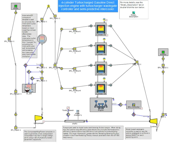
FRM Case 8
Results- After the simulation the power output for all cases is as follow.
|
case 1 |
case 2 |
case 3 |
case 4 |
case 5 |
case 6 |
case 7 |
case 8 |
|
|
Brake Power [kW] |
156.3 |
156.3 |
156.4 |
156.4 |
156.4 |
156.4 |
156.4 |
149.5 |
|
Brake Torque [N-m] |
298.5 |
298.6 |
298.6 |
298.6 |
298.6 |
298.6 |
298.6 |
285.5 |
|
Air Flow Rate [kg/h] |
582.1 |
582.2 |
579.3 |
579.1 |
579.2 |
576.4 |
584.4 |
593.3 |
|
BSFC [g/kW-h] |
353.8 |
353.9 |
352 |
351.9 |
352 |
351.3 |
355.3 |
377 |
|
A/F Ratio |
10.53 |
10.52 |
10.52 |
10.52 |
10.52 |
10.49 |
10.52 |
10.53 |
|
Period |
Time |
CPU |
Fraction |
|
|
case 1 |
17 |
0.408 |
5.26 |
12.89216 |
|
case 2 |
18 |
0.432 |
2.98 |
6.898148 |
|
case 3 |
37 |
0.888 |
4.86 |
5.472973 |
|
case 4 |
45 |
1.08 |
5.25 |
4.861111 |
|
case 5 |
43 |
1.032 |
4.41 |
4.273256 |
|
case 6 |
53 |
1.272 |
1.52 |
1.194969 |
|
case 7 |
18 |
0.432 |
0.45 |
1.041667 |
|
case 8 |
38 |
0.912 |
0.66 |
0.723684 |
Conclusion - So it is seen that as we go for frm approach the time taken in actual and simulation is almost same.
So it is better to go for FRM approach where detail reports are not required. And time constraint is issue.