Week 4.1: Project - Steady state simulation of flow over a throttle body
Aim- Steady state simulation of flow over a throttle body
Steps –
- Import the geometry in converge software.
- Define the boundary.
- Case setup
- Simulation
- Post processing
- Out puts
Case setup For throttle body –
Application type – Time based
Pre defined mixture - Air
Gas simulation – Default
Global transport parameter – Default
Reaction mechanism – Default
Simulation Parameter –
Run parameter – Steady based solver
Simulation time parameters-
Start time - 0 cycles
End time - 15000 cycles
Initial time set up – 1e-9 sec
Minimum time set up – 1e-9 sec
Maximum time set up – 1 sec
Solver parameters- Pressure based
Boundary condition –
Inlet – Inflow (Boundary type )
Outlet – Outflow (Boundary type )
Throttle body - wall(Boundary type )
Throttle- wall (Boundary type )
Intial condition and events –
Initial region is defined for air
Physical models –
Turbulence modelling [RNS _EPS_RNG]
Grid control –
Base grid – dx - 0.004
dy – 0.004
dz – 0.004
Fixed Embedding
Output processing - Default
Advanced parameter - Default
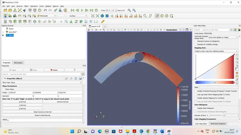
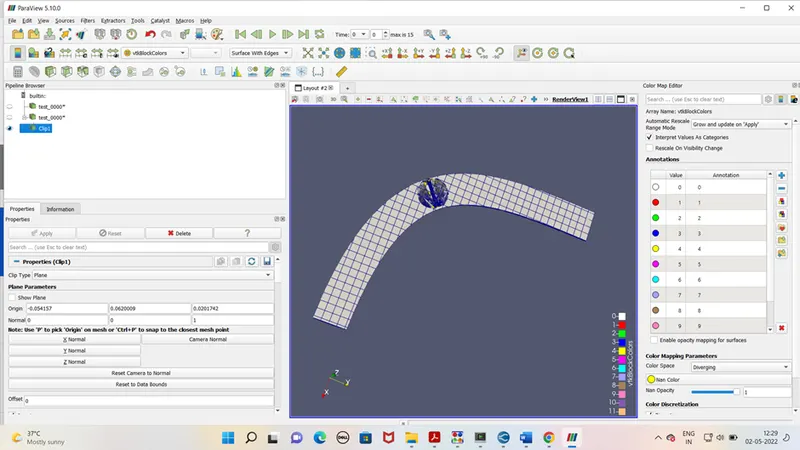
After case set up exports the file to defined folder. Run the simulation in the Cygwin. Generate the output files. As output file is generated run the post processing in Cygwin again. Open the output file in paraview for the mesh view and contours. For excessing pressure , velocity and mass flow rate use line plotting tab.
Outputs -
Mesh -
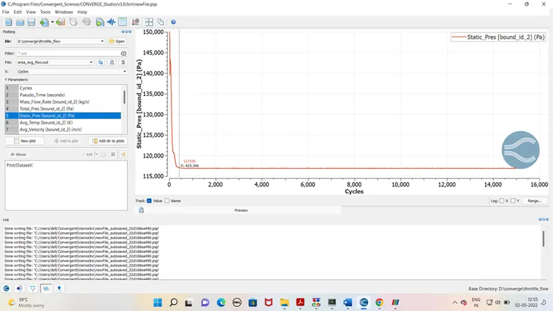
Pressure graph at inlet
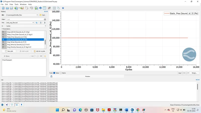
Pressure graph at oulet
velocity graph at inlet
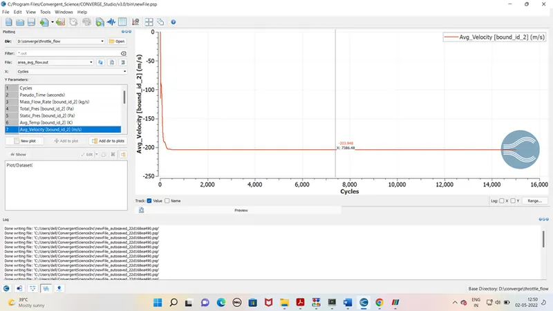
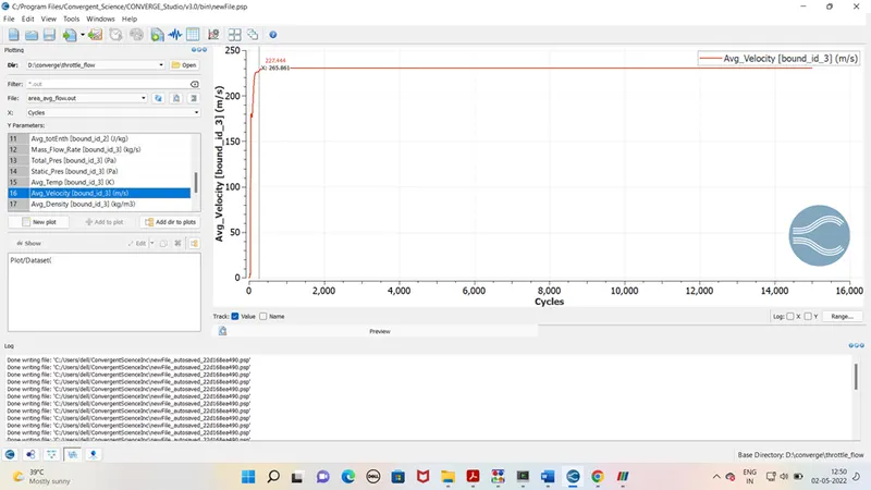
Velocity graph at outlet
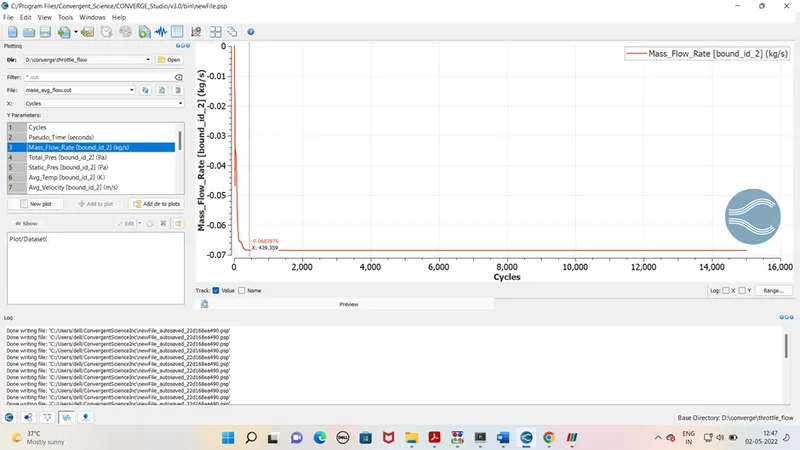
mass flow rate at inlet
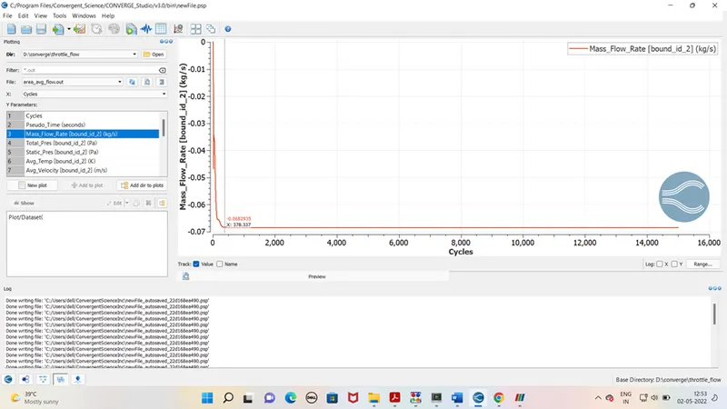
mass flow rate at oulet
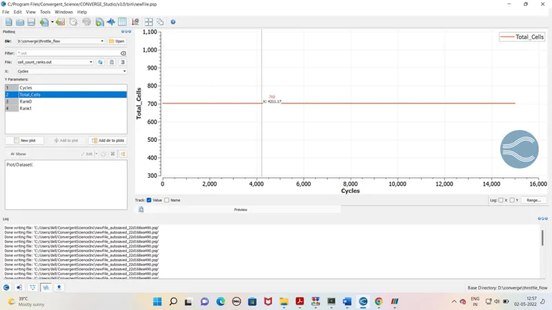
Total cells -
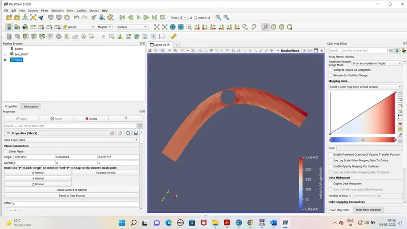
velocity contor -
Pressure contor -