Week 9 - Project 1 - Door Applique Design with Engineering Features
- Aim: Create the Base Bracket Plastic component through the given Class-A surface.
- Objectives:
- To create a tooling axis.
- To create class B.
- To capture all the features mentioned on the surface.
- Method:
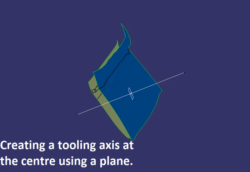
- First, it is necessary to capture the tooling axis, and it is shown in the below images.
 |
|
|
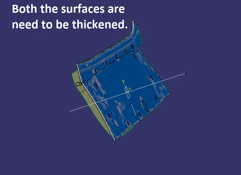
As we need to capture the solid and all other features, it is necessary to thicken both upper and lower surfaces. |
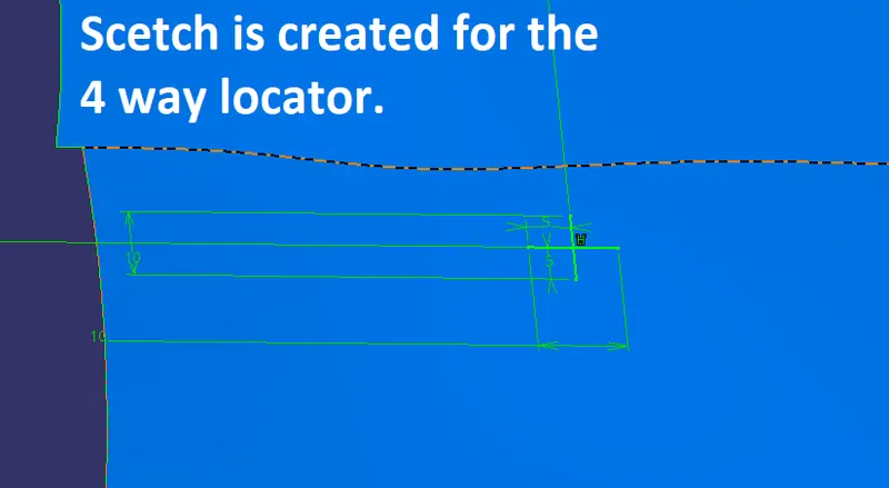
To capture the 4-way locator, it is necessary to create a sketch and pad it with a certain thickness, as it is an open sketch, it is necessary to thicken it while padding, otherwise it will show some error. |
|
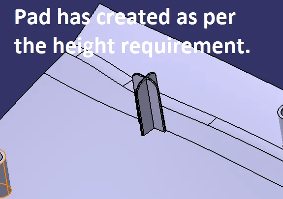
As per the stated height, a pad is created and along with that, chamfer and fillets need to be given. |
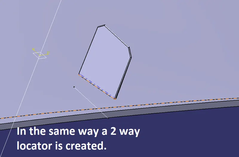
After creating a 4-way locator, a 2-way locator is also needed at some other place. To capture it, again a sketch is created and in the same way, a pad is done. While padding it is also necessary to pad it in another direction towards the surface to make sure it connects with the surface. |
|
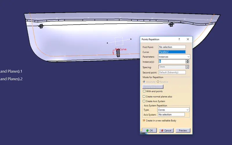
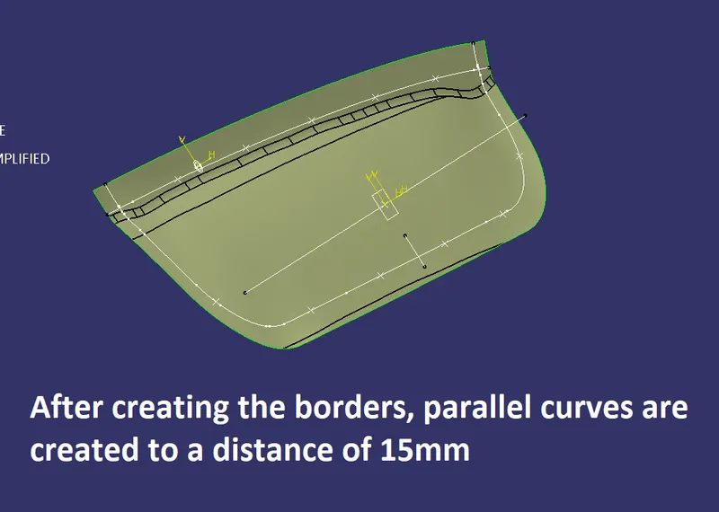
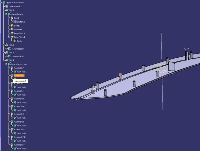
To provide the heat stakes, the border is taken as references and it is divided into several sections where points are created and on which the heat stake will be created. |
This is used to provide heat stakes and create a point on the border on which the sketch will be created. |
|
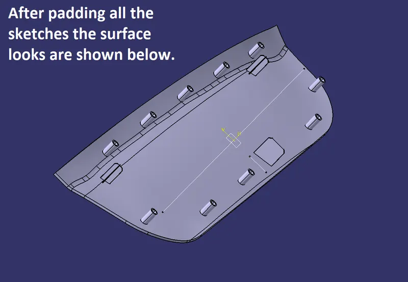
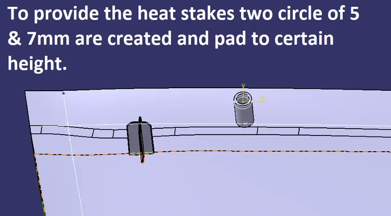
To create the heat stakes, two circles with mentioned dia are created and the pad is performed. While padding it is also necessary to pad it in both directions so to make sure it will come in contact with the below surface. |
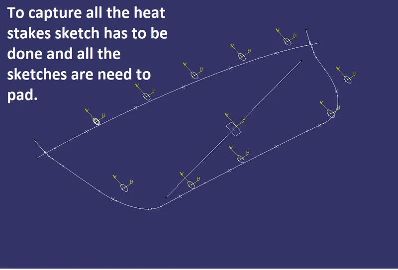
To capture all the heat stakes, it is necessary to create the sketch at different places and pad them. |
 |
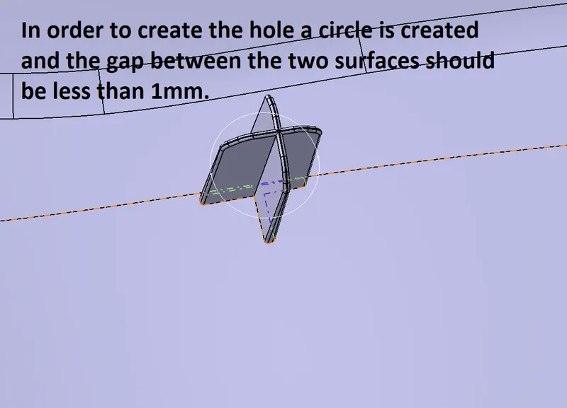
It is necessary to make sure the same features are captured in the upper surface as well. |
 |
|
|
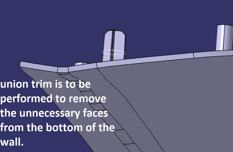
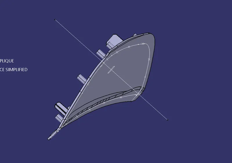
The feature extended below must be union trimmed and |
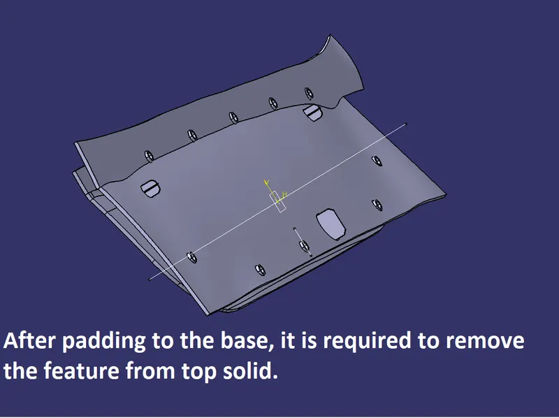
To make sure the heat stakes and locator pass from the top surface it is also necessary to create the holes in the upper surface. |
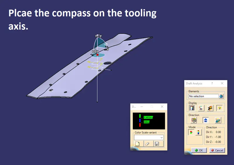 |
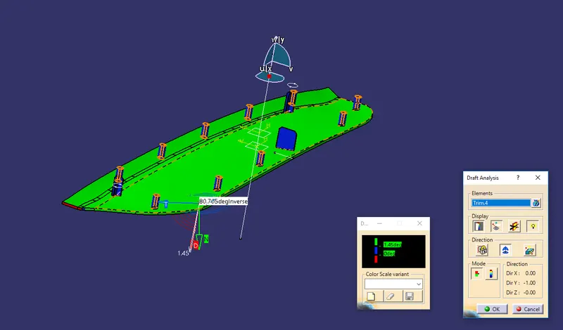
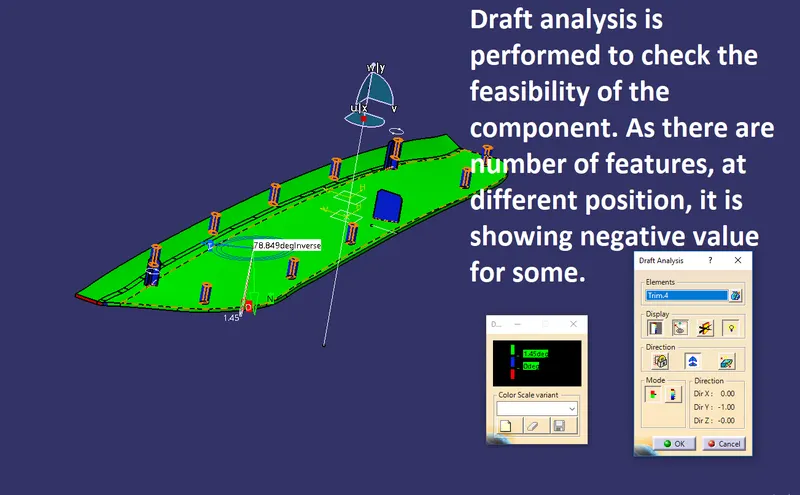
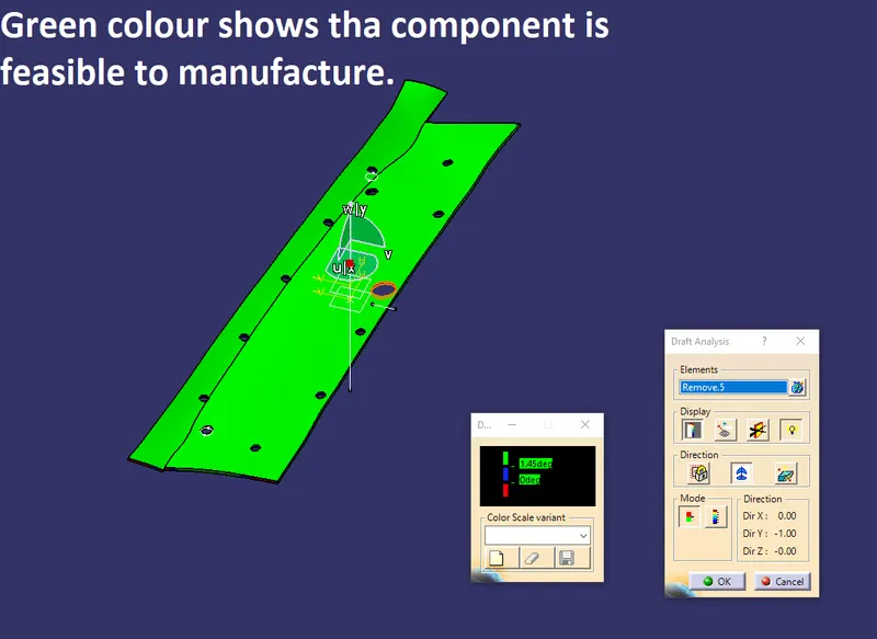
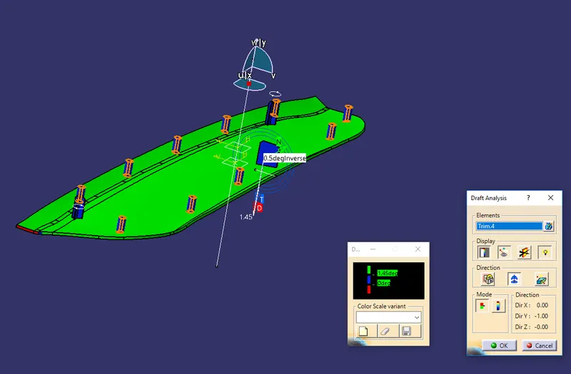
Draft analysis has to be performed in order to check the feasibility of the part. As the different feature are having different draft angle, it is necessary to check it individually. |
|
|
|
|
|
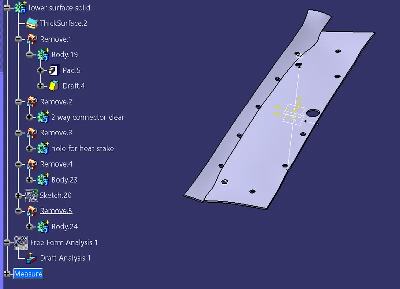
Complete tree structure |
- Learning outcome:
- To capture the tooling axis.
- To create class B and other features.
- To know about the heat stakes, 4-way & 2-way locators.
- To perform draft analysis.