Week 8 Multi cell Battery Pack
- Aim: to study how weakest cell limits the usable capacity of the battery pack? What is the solution?
- Method:
- Electric vehicles (EV) are widely viewed as an essential technology for energy-saving and environmentally sustainable transportation. As the new traction requirements, critical energy sources of EV, lithium-ion (Li-ion) battery pack is drawing a vast amount of attention for its advantages, such as compact volume, large capacity, higher energy density, and better safety.
- Single battery cells are serially and parallelly connected to make a battery stack to achieve higher voltage and capacity. However, the charging and discharging process need to stop as soon as any cell reaches its maximum limit or working threshold (below the absolute threshold). Due to this, the capacity of the battery pack is limited by the imbalance in the cells of the pack. This reduces the energy usage efficiencies and shortens the lifetime of the battery pack.
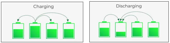
- There are two popular ways of balancing, namely passive balancing and active balancing. The conventional passive balancing method prevents the bleeding of excess energy from cells into heat, while in active balancing there is a transfer of the excess energy into energy-depleted cells.
- With proper battery pack integration and improved thermal management, the battery pack experiences lesser imbalance in a lifetime and the overall requirement of balancing is not very extensive but a must-have feature. The passive balancing with the proper board-level thermal management can handle all balancing requirements with cost-effective solutions.
- Cell balancing is the process of equalizing the voltages and state of charge among the cells when they are at a full charge. No two cells are identical. There are always slight differences in the state of charge, self-discharge rate, capacity, impedance, and temperature characteristics. This is true even if the cells are the same model, same manufacturer, and the same production lot. Manufacturers will sort cells by the similar voltage to match as close as possible, but there are still slight variations in the individual cells impedance, capacity, and self-discharge rate that can eventually lead to a divergence in voltage over time.
- Active Cell Balancing During Discharge
The diagram below represents a typical battery stack with all cells starting at full capacity. In this example, full capacity is shown as 90% of charge because keeping a battery at or near its 100% capacity point for long periods of time degrades lifetime faster. 30% represents fully discharged to prevent deep discharge of the cells.
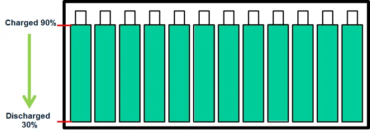
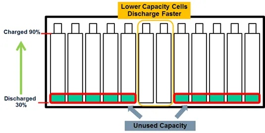
- It can be seen that even though there may be quite a bit of capacity left in several batteries, the weak batteries limit the runtime of the system. A battery mismatch of 5% results in 5% of the capacity unused. With large batteries, this can be an excessive amount of energy left unused. This becomes critical in remote systems and systems that are difficult to access since it results in an increase in the number of battery charge and discharge cycles, which reduces the lifetime of the battery, leading to higher costs associated with more frequent battery replacement. With active balancing, the charge is redistributed from the stronger cells to the weaker cells, resulting in a fully depleted battery stack profile.
- Active Cell Balancing While Charging
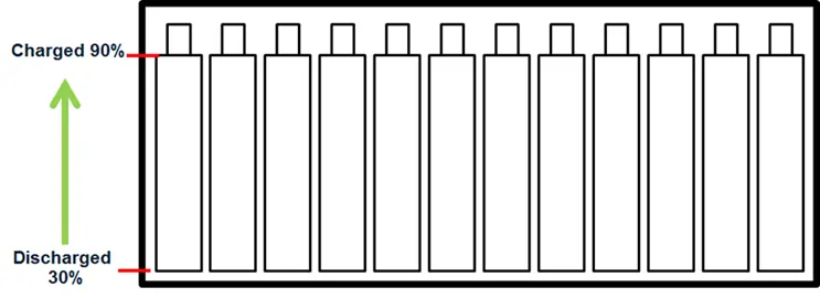
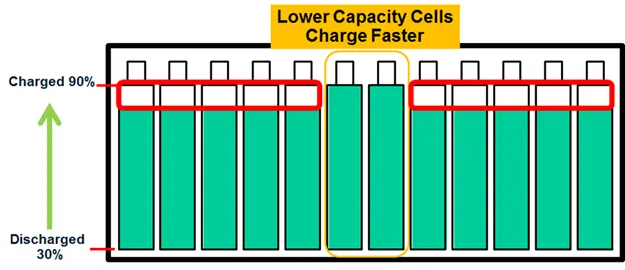
When charging the battery stack without balancing, the weak cells reach full capacity prior to the stronger batteries. Again it is the weak cells that are the limiting factor; in this case, they limit how much total charge our system can hold. The diagram below illustrates charging with this limitation.
- Passive cell balancing:
- The above figure shows the basic diagram of a typical shunting resistor passive cell balancing. This topology supports the simultaneous balancing of multiple cells and achieves the balancing by dissipating energy from energy-filled cells in the respective resistors.
- The important factors for consideration of this architecture are, the Resistance sizing with balancing current and balancing time. Also, the thermals for heat dissipation need to evaluate to eliminate the degrading of the system. In general, the onboard passive balancing current ranges from a few hundreds of milliamperes to around 1 Ampere, and hence the effective balancing time calculations heavily depends on balancing current. Also, the balancing current is directly proportional to cell voltage and hence it's not constant throughout the charge cycle.
- There are possible tweaks in the basic architecture to enable it for larger balancing current but eventually its a trade-off for balancing current and required balancing time with the cost. The overall architecture and implementation of passive balancing are very economical with reduced complexity.
- References:
- https://www.ionenergy.co/resources/blogs/cell-balancing-better-performance/