Week 5 Battery characteristics using drive cycle
Aim: Simulate generic battery model charge-discharge using UDDS data.
Method:
- For the given problem the UDDS cycle has been provided by the instructor.
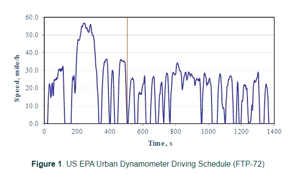
- The EPA Urban Dynamometer Driving Schedule (UDDS) has been developed for chassis dynamometer testing of heavy-duty vehicles. The UDDS schedule as a basis for the development of the FTP transient engine dynamometer cycle.
- There is also other HD UDDS cycle stands for heavy-duty UDDS and it should not be confused with UDDS. The US FTP-72 (Federal Test Procedure) cycle is also called the Urban Dynamometer Driving Schedule (UDDS) or LA-4 cycle (CFR 40, 86, App.I).
- The image shown below shoes the UDDS cycle.
- In the given problem as per the requirement the Simulink model has been done. This model consists of a signal builder block, constant current block, a cell block, a bus separator, a scope and a powergiu block.
Cell:
- Library: Simscape / Electrical / Specialized Power Systems / Electric Drives / Extra Sources
- The Battery block implements a generic dynamic model that represents most popular types of rechargeable batteries. This figure shows the equivalent circuit that the block models.
Signal builder:
Create and generate interchangeable groups of signals whose waveforms are piecewise linear
Library: Simulink / Sources
Powergui: Environment block for Simscape Electrical Specialized Power Systems models
Library: Simscape / Electrical / Specialized Power Systems / Fundamental Blocks
The powergui block allows you to choose one of these methods to solve your circuit:
- Continuous, which uses a variable-step solver from Simulink®
- Discretization of the electrical system for a solution at fixed time steps
- Continuous or discrete phasor solution
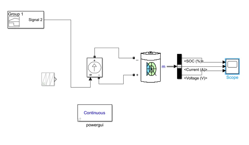
- The above model shows the diagram for the UDDS cycle problem. In the scope SoC, current and voltage output are taken.
- In order to give the input the signal builder block is used. However, the process to enter the values is not same for the given process. As the excel sheet has the values the variables are needed to be created.
- Hence two variables named time and speed are created in order to give the input in signal builder block.
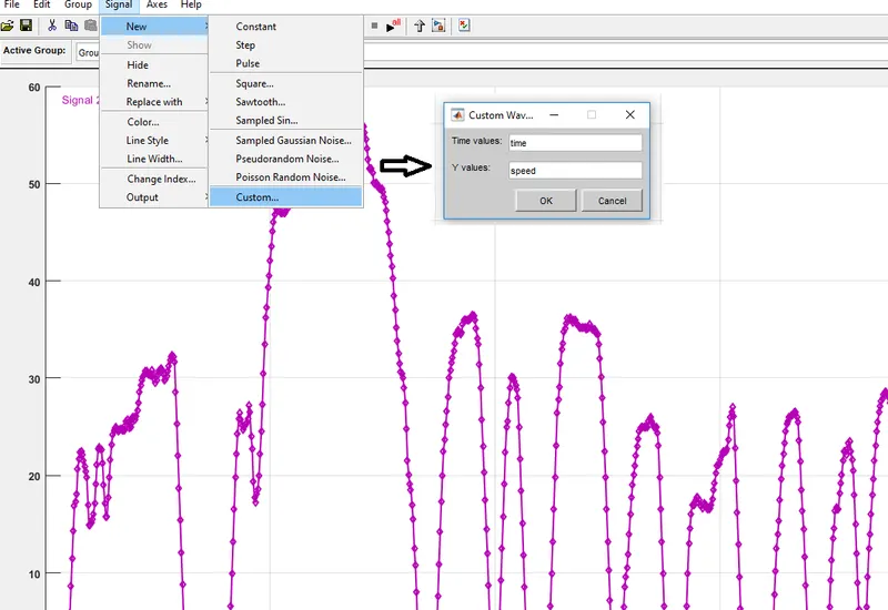
- The steps for the input are mentioned above. In order to give input first, it is necessary to replace the existing values. In this case, first, select the Replace with option and enter the time and y-axis values. Again in order to display the same input, t is necessary to set the new values by following the same step shown in the image.
- In order to displace the input in signal builder block changes the time axis values to 1370 which is the final time value in the input. After given proper values the input values will come as shown below.
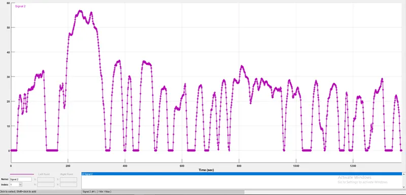
- After running the model the following output is obtained.
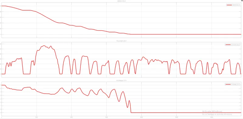
- The first plot shows the state of charge condition of the battery where it decreases from 100% to 0.
- The second plot shows the variation of current as per the requirement. Current follows some kind of similar path as that of cycle requirement. As this is the source current it follows the same kind of behaviour.
- The third plot shows the voltage requirement, where it can be seen that wherever the current is coming to 0 the voltage will be maximum at that stage.
- As the SoC becomes 0 there would not be any voltage passing through the circuit.
- Learning outcome:
- To create a model for the given problem.
- The use the signal builder block in order to give the input time and speed.