3D solid meshing of Rearview mirror
Rearview mirror
- Aim: Understanding the Volume mesh where we try to convert tria elements made on the surface into the tetra elements and volumetric tetra elements inside the empty volume shell.
- Objectives:
- Getting introduced to the new area of volume mesh.
- Understanding the areas where the solid mesh is done and the difference between solid and shell mesh.
- Understanding the process of generating the tetra elements on the surface.
- Generating the tetra elements and forming solid volume.
- Body of Content
3.1 Geometry check:
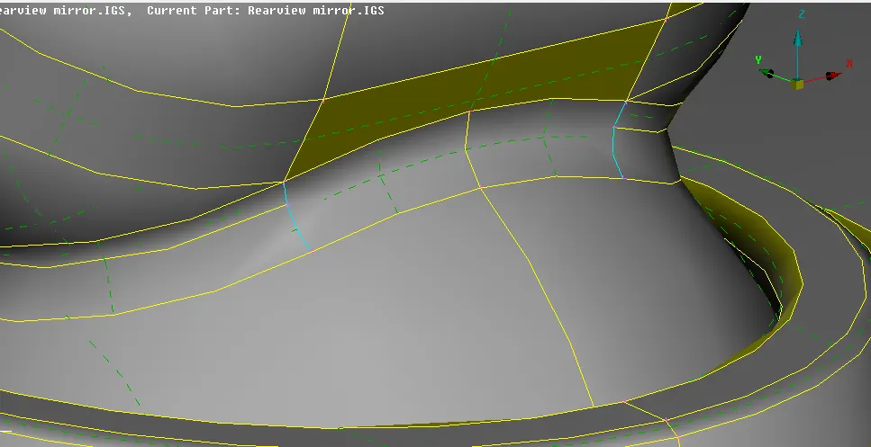
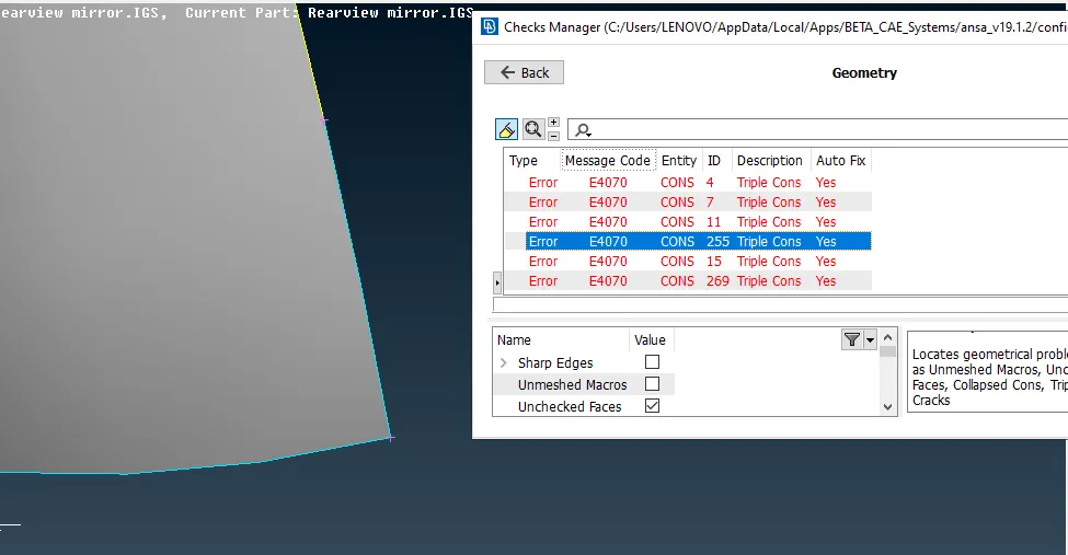
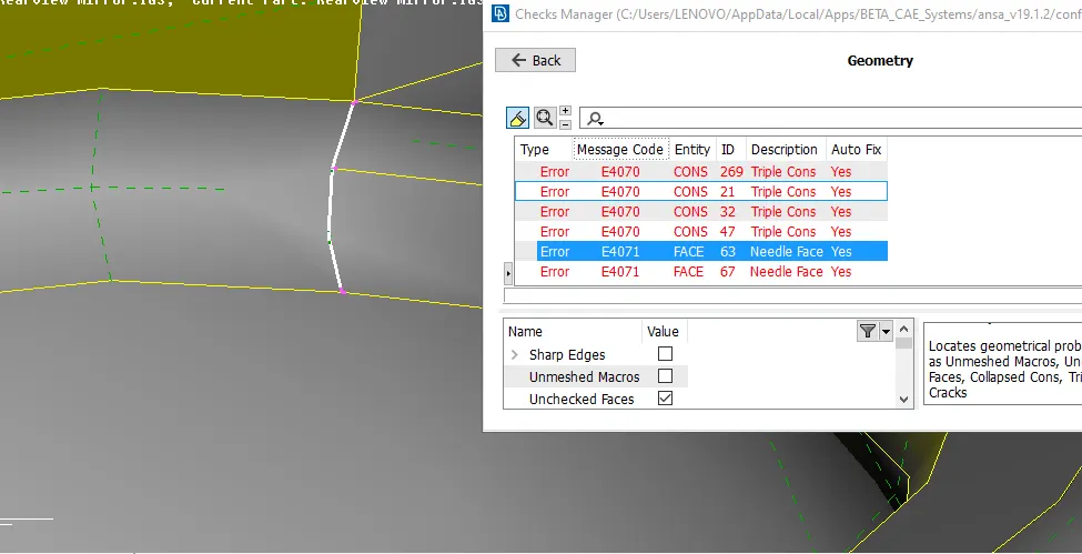
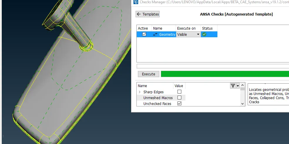
- This is the initial stage of any meshing procedure. It enables the user to identify the errors like needle face, cracks and unnecessary triple cons. Here it is necessary to remove these errors so that it won’t create any further errors.
- In the current model, as there were no cracks, but the needle faces and some triple con generated due to topology and these need to be corrected before moving ahead.
|
Image 3.1.1 |
Image 3.1.2 |
|
Image 3.2.3 |
Image 3.2.4 |
3.2 Tetra Meshing:
- Generating the mesh on the outer surface is the first step of volume meshing.
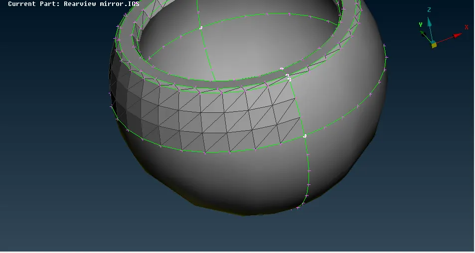
- In this Ortho Tria is used to generate mesh on the areas where there is a fillet or curved surfaces as it capture the circular areas better compare to normal tria, which causes surface distortion.
- On the flat surface, normal tria can be used as it will form a mesh which is quite similar to Ortho tria.
- So a combination of Ortho tri and normal tria can be used in order to obtain a quick result.
- This combination is preferred because the computational time for ortho tria is more compare to normal tria.
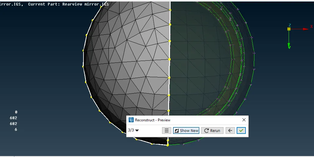
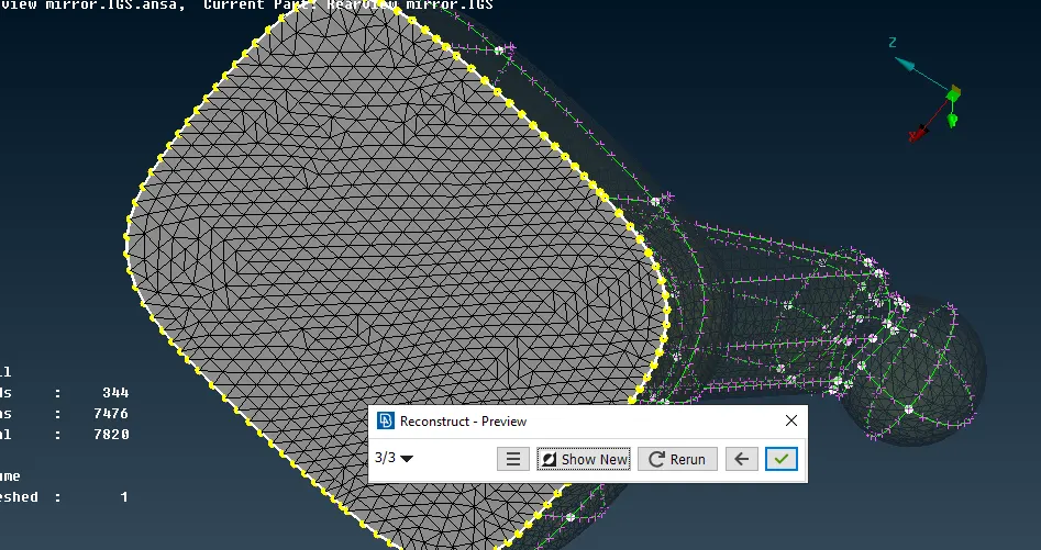
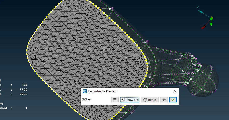
- Following are the images which show the meshing done on the surface.
|
Image 3.2.1 Begining the meshing with a single surface. |
Image 3.2.3 Step by step formation of Ortho tri on the curve surface |
|
Image 3.2.4 Reconstructing the mesh in order to obtain better mesh |
Image 3.2.5 Better mesh obtained after performing remesh command. |
3.3 Solid mesh:
- Tetrahedral is a four nodded solid element which can be generated through tria element by creating a volume and also through the existing volume of geometry.
- These elements are used where the geometry has high thickness and complexity.
- It has 4 triangular faces with 4 nodes joining them.
3.4 Method to generate Tetra mesh:
1. Convert 2D tria to Tetrahedral element, using tetra mesh panel.
2. Using quick tetra mesh from the utility panel.
3. Using volume tetra mesh panel.
|
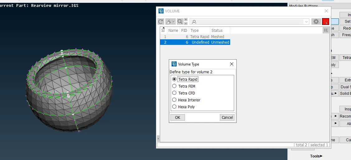
Image 3.4.1 Defining the entity in V.Mesh section and performing the Remesh command to convert it into volume mesh. |
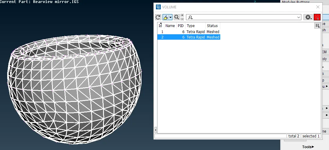
Image 3.4.1 After the mesh has been performed. ANS shows meshed in the box. |
|
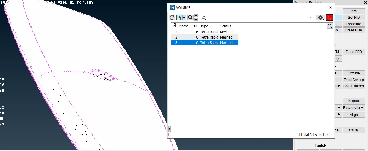
Image 3.4.2 Performing V.mesh to other parts |
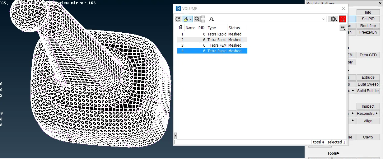
Image 3.4.4 Performing V.mesh to other parts |
4. Learning Outcome:
- Getting introduced to the Volume mesh.
- Different methods of doing volume mesh and how to deal with collapse errors in the mesh.
- Difference between where to use shell and volume mesh.
- Introduction to Tetrahedral mesh.
5. Conclusion:
- Obtaining the Volume mesh with minimum errors and understanding the basic command to generate the volume mesh.
- Getting introduced to the new section of ANSA called V.mesh.
- Study of V.mesh and use of Ortho tria.
link for the model: https://drive.google.com/file/d/1jsv3n8NtkVON4ey7km-B2zj6TgKeTtVs/view?usp=sharing