Mid surfacing and meshing of Bottle cap compenent
Bottle Cap Meshing and Mid Surface
- Aim: Meshing the bottle cap model, which consist of taking the mid surface of complex shapes and understanding the basic procedure.
- Objectives:
- Taking the mid of complex shapes.
- Using new commands like Revolve for translation operation.
- Mid formation of teeth and thread.
- How to use COG command to insert centre point for translation operation.
- Body of Content
3.1 Geometry check:
- This is the initial stage of any meshing procedure. It enables the user to identify the errors like needle face, cracks and unnecessary triple cons. Here it is necessary to remove these errors so that it won’t create any further errors.
- Here in this particular part, there were several cracks which are formed due to stitching errors when two surfaces are not properly stitched. Also, there were some other errors like needle face which has to be removed.
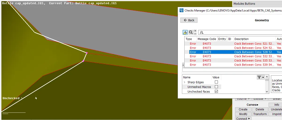
Image 3.1.1 Crack in geometry to be removed
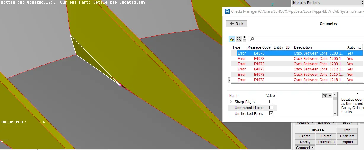
Image 3.1.2 Crack in geometry to be removed
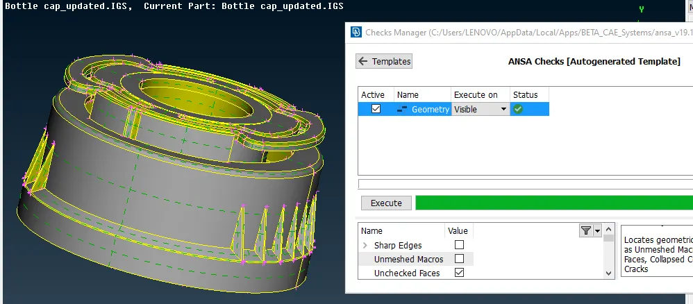
Image 3.1.3 Complete geometry clean up
3.2 Mid Surface Formation:
-
As this is a complex component there are some places where it is a tricky job to extract a mid surface. Here are some images are shown below which shows the complex areas where the mid has been taken.
-
It can be seen that at some places it is recommended to extract the mid by using the middle con command which enables us to form the mid of two cons and it is also recommended to join those cons which will reduce the number of Hot points which can restrict the formation of smooth flow.
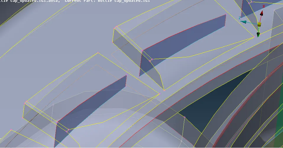
Image 3.2.1 Mid surface of Teeth
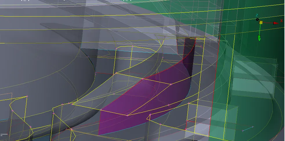
Image 3.2.2 Mid surface using offset command
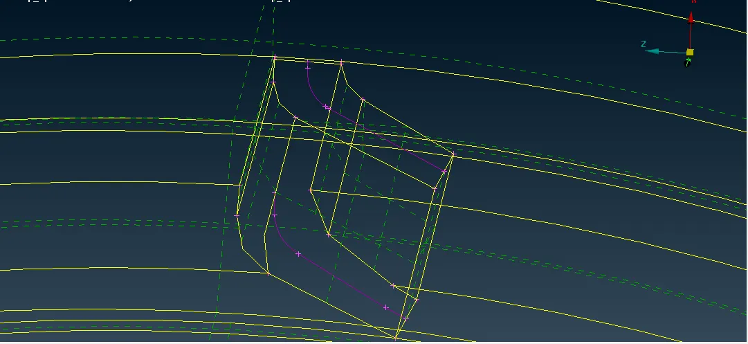
Image 3.2.3 Smooth Mid surface formed using Curve-->Middle
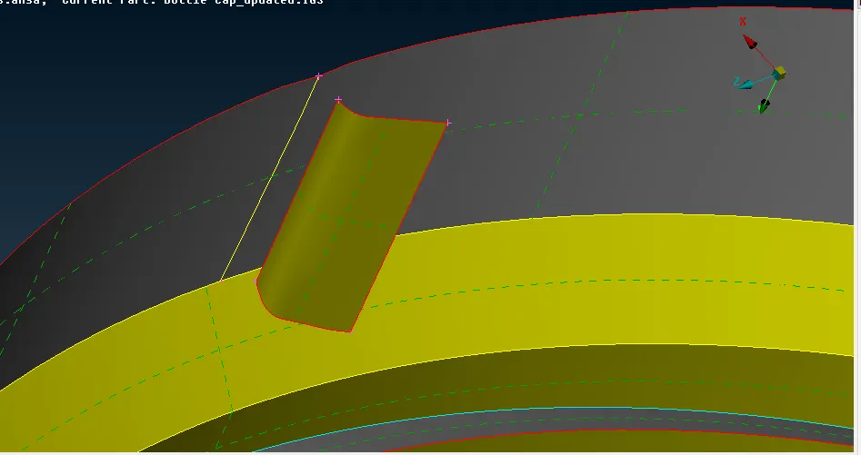
Image 3.2.4 Mid surface of a complex area
Use of Rotary command to copy and transform the single entity which in a number of places, but in a rotary path. Following are the steps which are needed to be followed in order to get the mid surface in a rotary path.
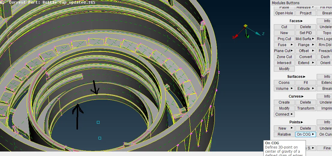
Image 3.2.5 Form two Centre using On COG command at two different height.
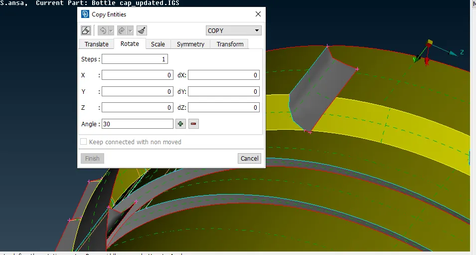
Image 3.2.6 Select Transform command & select the entity. Then in Rotary section enter the steps.
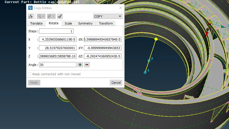
Image 3.2.7 Select one centre point for X & another for dx. ANSA will select the path accordingly and also enter the angle(degree/number of steps). After entering the values accept the command.
3.3 Meshing:
-
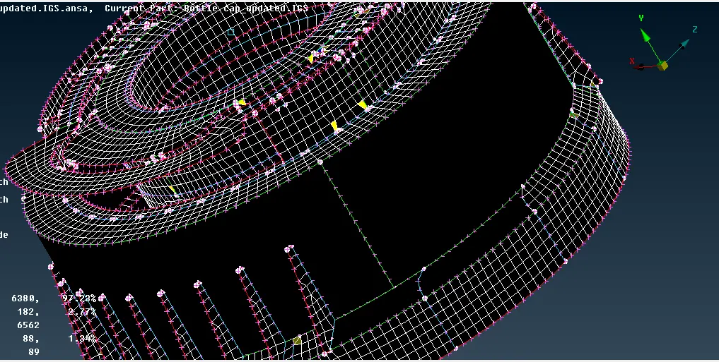
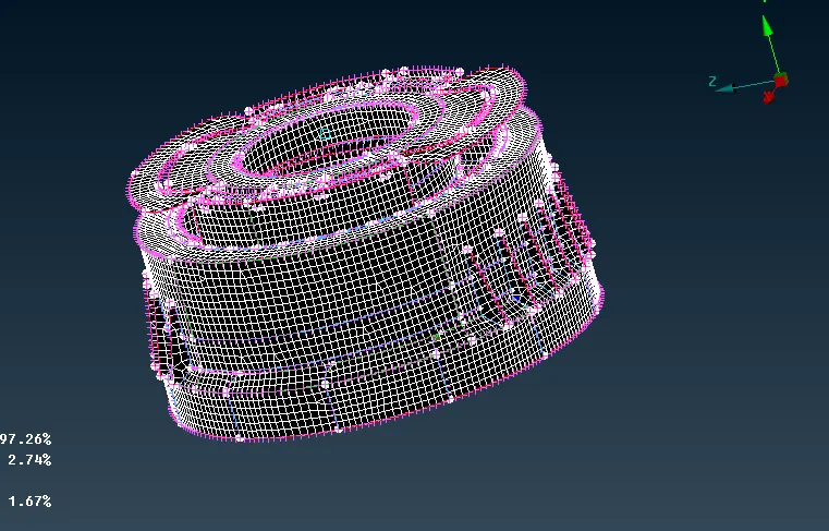
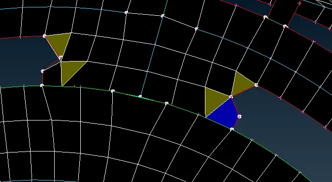
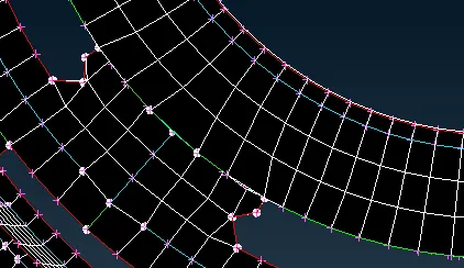
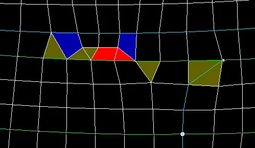
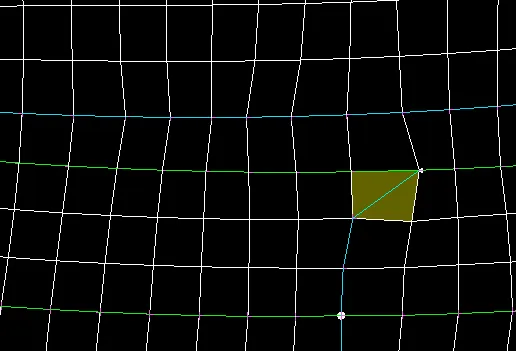
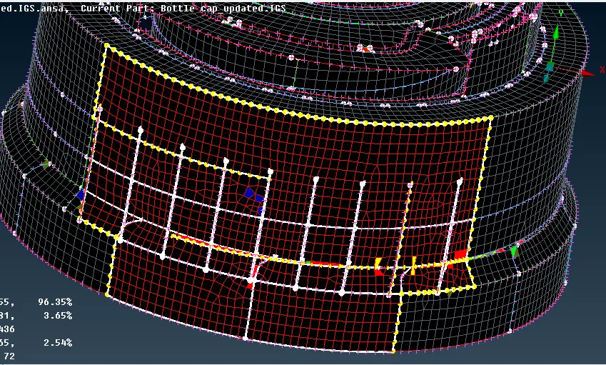
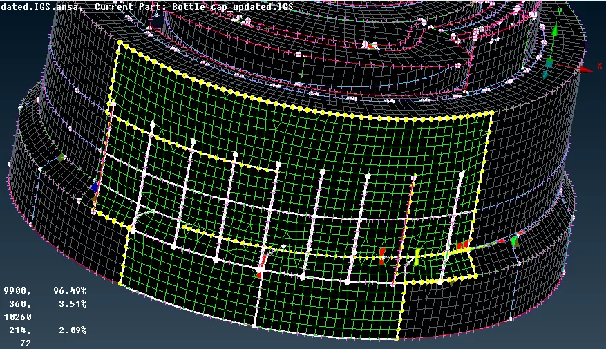
As this is a complex part of the meshing is a time-consuming process for this as several cuts are to be made to have a smooth flow. Still, at some places, compromisations are made in order to avoid further more errors. Some of the images are shown below of how the errors are removed and some places where compromise is made to retain the better mesh.
-
It is also advisable to go through a sequence to get a smooth flow, forming the cuts wherever possible and avoiding two tri per nodes and maintaining the required quality standards.
|
Image 3.3.1 Step by step mesh formation |
Image 3.3.2 Complete mesh |
|
Image 3.3.3 Errors to be removed |
Image 3.3.4 Errors removed |
|
Image 3.3.5 Mesh Before |
Image 3.3.6 Mesh After |
|
Image 3.3.7 Reconstruct to improve mesh(before) |
Image 3.3.8 After using reconstruct command |
- Learning Outcome:
- Extracting the mid surface of complex parts like threads and teeth.
- Meshing of these complicated areas.
- Learning the new command for Centre formation and middle curve formation
- Conclusion:
- Obtaining the perfect mesh with contour shapes is not permissible. We have to keep tri elements in such areas to avoid any further distortion in the mesh.
- To achieve a good mesh sometimes it is necessary to compromise on the mesh structure and allow some tri elements near to each other.
- Working on some intricate shapes is leading to compromise on mesh and it is also advisable to remove unnecessary construction lines to form a better mesh.
Model link: https://drive.google.com/file/d/1NjQeIBTNjIaIGFQHfG--Ck1_4qtw7lBj/view?usp=sharing