Week 9 - Parametric study on Gate valve.
AIM:
To perform a parametric study on the gate valve simulation by setting the gate opening from 10 % to 80%.
- Obtain the mass flow rates at the outlet for each design point and calculate the flow coefficient and flow factor.
INTRODUCTION:
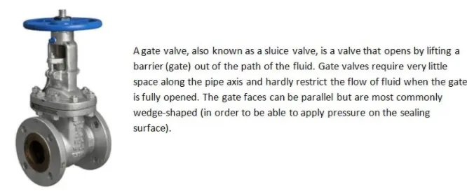
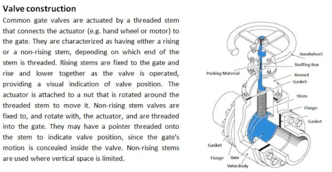
Gate valves are widely used for all types of applications and are suitable for both above-ground and underground installation. Not least for underground installations it is paramount to choose the right type of valve to avoid high replacement costs.
Parametric study of gate valve:
A parametric analysis or sensitivity analysis is the study of the influence of different geometric or physical parameters or both on the solution of the problem. The impact of changing certain parameters on the design can be assessed as we mmove forward in the design. The parameters can include dimensional parameters. Parametric studies allow you to nominate parameters for evaluation, define the parameter range, specify the design constraints, and analyze the results of each parameter variation. In this parametric study, the gate valve opening is taken as an input parameter to study the affect on the mass flow rates which is the output parameter.
Step by step preparation of the model for analysis using ANSYS FLUENT:
Geometry: A STEP format geometry is imported into ANSYS spaceclaim. The gate valve geometry is shown below:
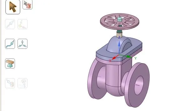
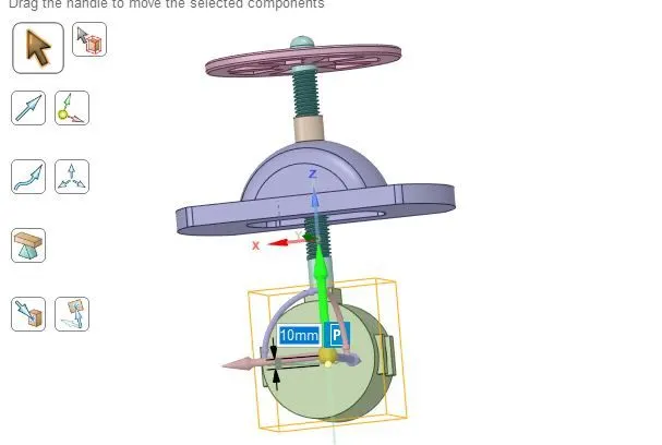
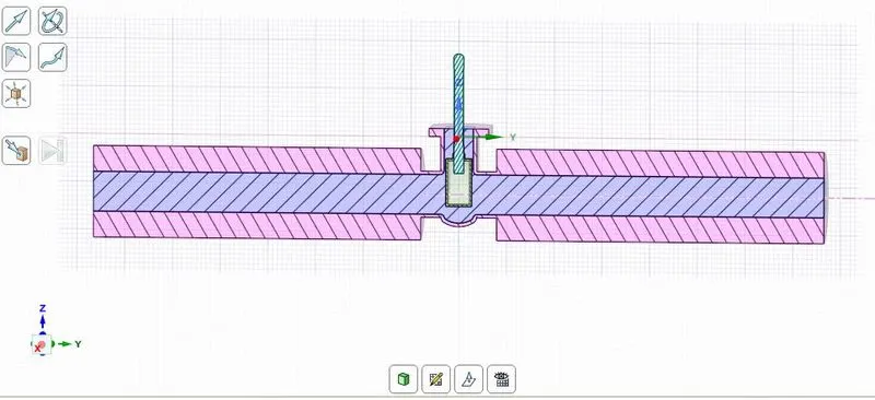
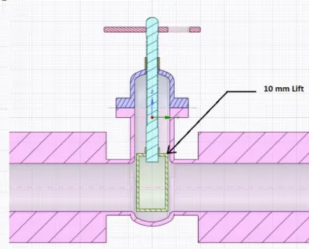
The gate disc inside the casing is moved by 10mm for the first simulation and then the distance is parametrized in further cases. The disc is moved 10 mm as shown below:
Pull the inlet and outlet openings by 800 mm to capture the inflow and outflow patterns of the fluid accurately.
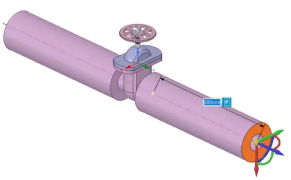
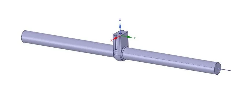
The fluid volume is extracted from the obtained geometry by selecting the appropriate edges. The fluid volume generated is shown below:
The fluid volume for a gate opening of 10 mm with the outer casing is shown though a cut section below:
MESH:
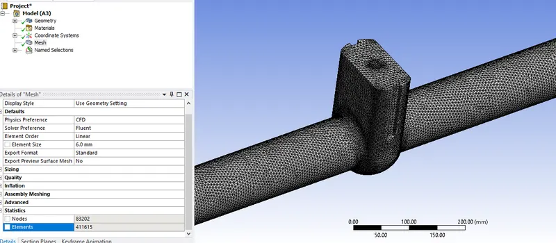
Mesh is generated with an element size of 6 mm as shown. The total number of elements generated are 411615 as evident from the statistics.
FLUENT solver setup:
A steady state pressure based solver with gravity enabled is chosen for the current study. The fluid is taken as water.
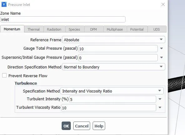
The inlet is taken as pressure boundary condition with 10 Pa pressure as shown below:
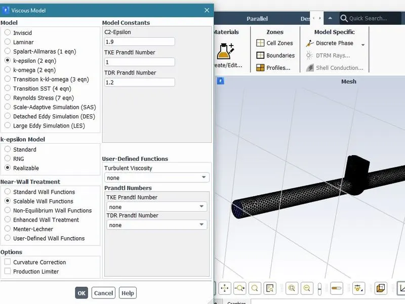
To determine the velocity at the inlet, initialize the solution from the inlet using standard initialization. The velocity comes out to be approximately 0.15 m/s . The corresponding reynolds number will be approximately 14000 which is greater than 2000 for a laminar flow inside the pipe. Hence a k-epsilon realizable model with scalable wall functions is chosen for the current study.
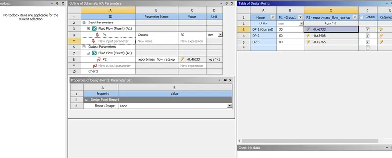
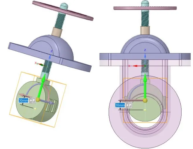
The gate opening lift parameter is created to observe the mass flow rates for each openining. The lift values considered are 10,30,50 and 80 mm for the present study. The parametric setup is shown below:
Results and Discussion:
1) Gate valve opening of 10 mm:
The lift is 10 mm as shown below:
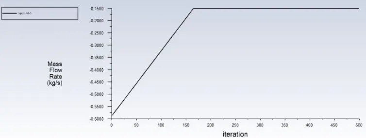
The plot for the mass flow rate at the outlet is shown: The mass flow rate is approximately -0.151 kg/s
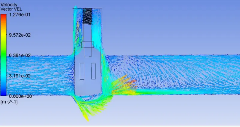
The velocity contours are shown below:
2) Gate valve opening of 30 mm:
The velocity vectors are shown across a plane along the pipe:
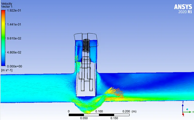
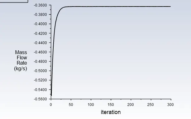
The mass flow rate at the outlet is found to be approximately -0.363 kg/s.
3) Gate valve opening of 50 mm:
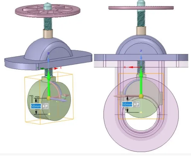
The disc opening is shown for a lift of 50 mm:
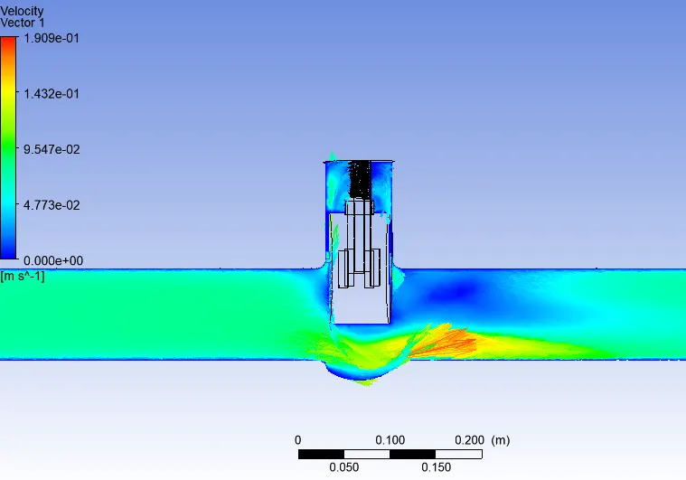
The velocity vectors are shown below:
The mass flow rate plot is shown:
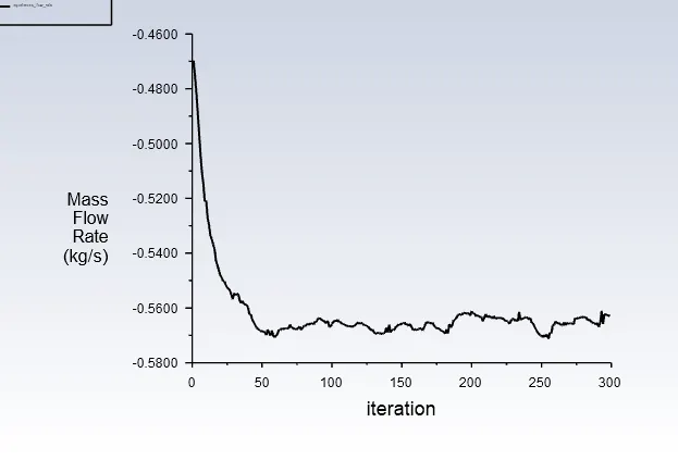
The mass flow rate at the outlet is found to be about -0.564 kg/s.
4) Gate valve opening of 70 mm:
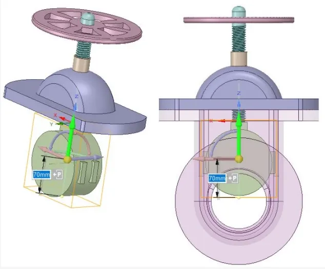
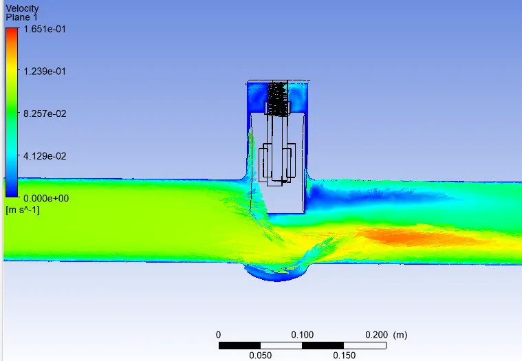
The flow field inside the pipe is shown:
The mass flow rate plot is shown:
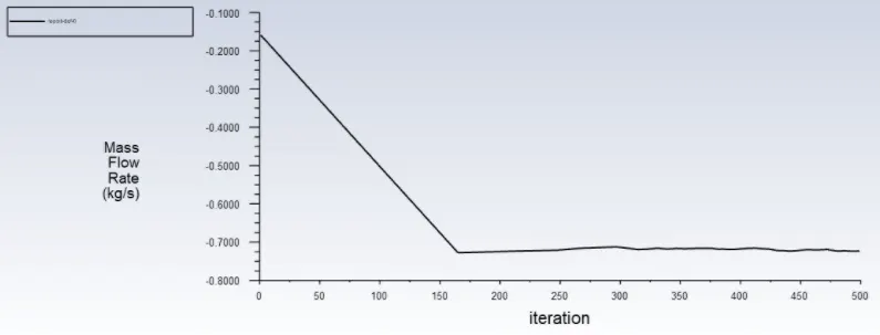
The mass flow rate for 70mm lift is about -0.722 kg/s.
5) Gate valve opening of 80 mm:
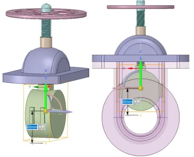
The flow field inside the pipe is shown:
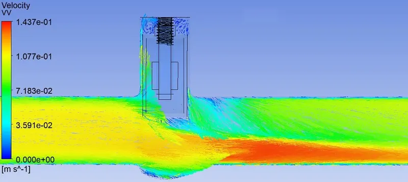
The mass flow rate is found to be approximately 0.789 kg/s.
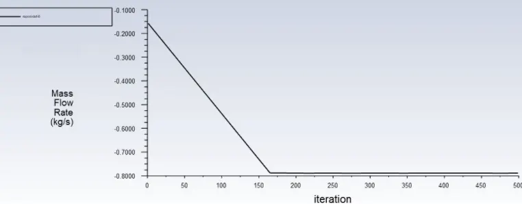
Flow Coefficient:
The flow coefficient of a device is a relative measure of its efficiency for allowing the fluid flow. It describes the relationship between the pressure drop across an orifice valve or other assembly and the corresponding flow rate.
Mathematically the flow coefficient Cv (or flow-capacity rating of valve) can be expressed as:
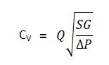
Where:
- Q is the rate of flow (expressed in US gallons per minute).
- SG is the specific gravity of the fluid (for water = 1).
- ΔP is the pressure drop across the valve (expressed in psi).
In more practical terms, the flow coefficient Cv is the volume (in US gallons) of water at 60 °F that will flow per minute through a valve with a pressure drop of 1 psi across the valve.The use of the flow coefficient offers a standard method of comparing valve capacities and sizing valves for specific applications that is widely accepted by industry. The general definition of the flow coefficient can be expanded into equations modeling the flow of liquids, gases and steam using the discharge coefficient.
SG =1; ΔP= 10-0 =10 psi;
Now for a lift of 10 mm,
Q=0.151 kg/s;
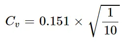
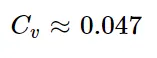
Kv can be calculated from Cv using the equation as given below:
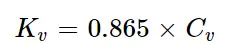
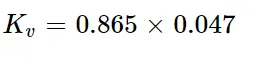
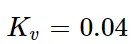
Similarly, the flow coefficient and flow factors for all the cases are calculated and tabulated below:
| Lift(mm) | Mass flow rate(kg/s) | Flow coefficient | Flow factor |
| 10 | 0.151 | 0.047 | 0.04 |
| 30 | 0.363 | 0.115 | 0.09 |
| 50 | 0.564 | 0.178 | 0.015 |
| 70 | 0.722 | 0.228 | 0.197 |
| 80 | 0.79 | 0.251 | 0.216 |
Observations:
- As opening or lift of the Gate Disc increases, velocity of the flow increases.
- There is a gradual increase in Mass Rate, Flow Coefficient and Flow Factor as Lift of the Gate Disc increases from a lift of 10 to 80 mm.
- At the front or inlet side of the valve, pressure is high. As flow passes through the valve opening, it decreases and at the outlet there are no any restrictions to the flow, so pressure becomes 0.
- When the valve if fully open, Mass Flow rate and Flow Coefficient and Flow Factor becomes maximum.