Final Project: Electric Rickshaw modelling
AIM:
- To create a detailed MATLAB-Simulink model of a mahindra treo electric rickshaw
- To verify the performance claimed by mahindra treo e- rikshaw as per the given parameters.
- For any three standard driving cycles, calculating the energy consumption, temperature rise of motor and controller.
THEORY AND MODELLING:
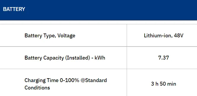
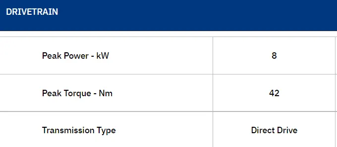
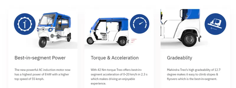
Mahindra Treo is a revolutionary new range of electric autos, e-rickshaw and cargo version. This comes under L5M -Auto category. The mahindra treo-sft model has a peak power of 8kW and a peak torque of 42 Nm. This is driven by a 48 V lithium ion battery that has a capacity of 7.37kW. The typical driving range for this vehcile is given as 130km for a single full charge.
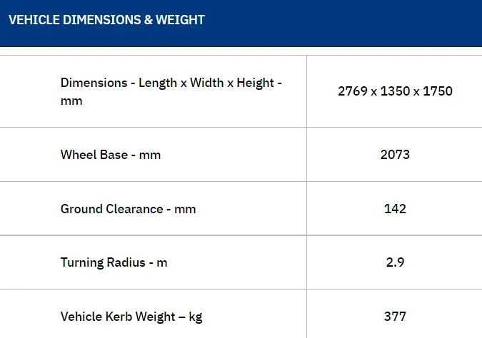
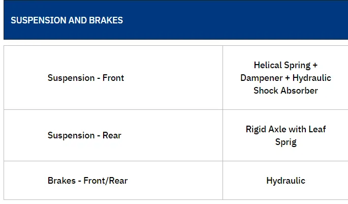
The technical specifications of the vehicle are given:
 |
 |
 |
 |
Block diagram for the simulink model:
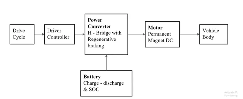
This mathematical model must be build before making an actual hardware design. A mathematical model offers a great flexibility in conceptual design modification. Repetitive road tests can be avoided and a best performance model with reasonable accuracy can be obtained. There are also certain limitations of mathematical models since these models cannot implement all the realistic aspects of the actual physical model.
A step by step procedure to build a simulink model for mahindra treo e-riskshaw:
a) Vehicle body and dynamics subsystem:
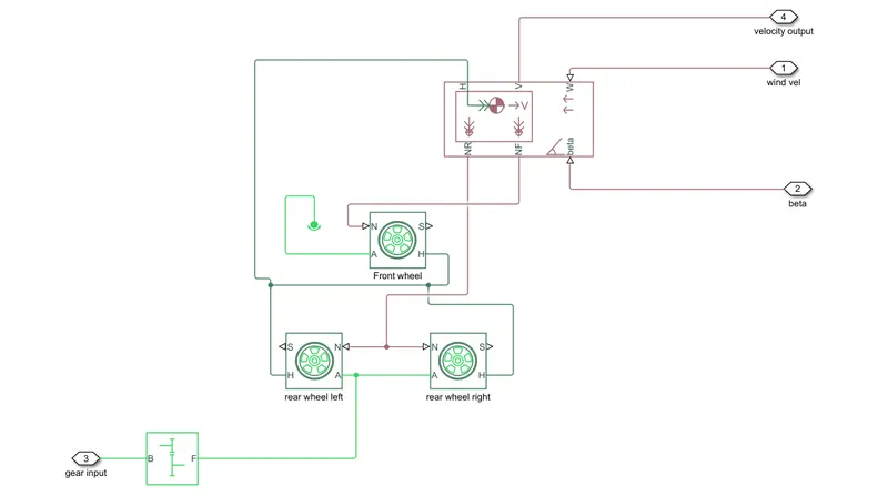
The wheels are modelled by magic tyre blocks built from tire-road Interaction (Magic Formula) and Simscape Foundation Library Wheel and Axle blocks. Optionally, the effects of tire inertia, stiffness, and damping can be included.
A is the mechanical rotational conserving port for the wheel axle
H is the mechanical translational conserving port for the wheel hub through which the thrust developed by the tire is applied to the vehicle.
N is a physical signal input port that applies the normal force acting on the tire.
S is a physical signal output port that reports the tire slip.
Since the e-rikshaw has a real wheel drive, the gear input shaft is connected to the rear axle and the front wheel is given a free rotation. These wheels are connected to the dynamics block. The dynamics block takes the wind velocity, the angle of inclination of the road, the resistant forces generated due to tyres and all other forces and calculated the power required by the vehicle to propel. This power is generated by the electric motor accordingly.
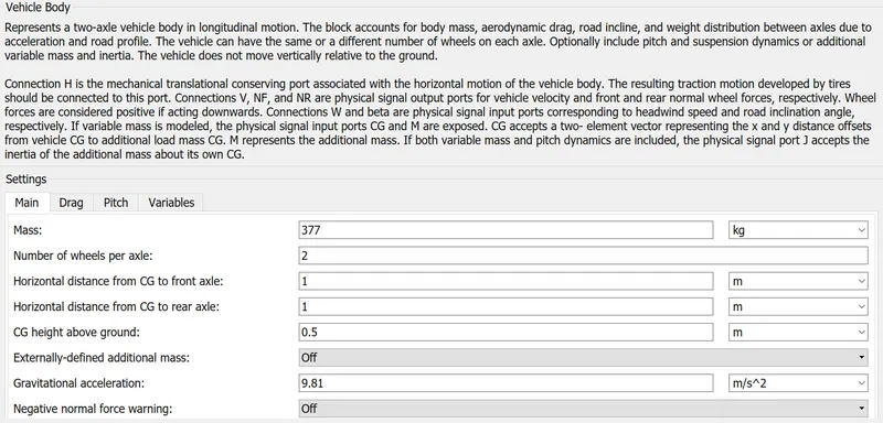
The kerb weight of the mahindra e-rikshaw is given to be approximately 377kg. A maximum weight 400kg for 4 passengers is added to the kerb weight of 377kg. Hence the maximum total weight of the vehicle considered is 777 kg. Assuming each tyre bears equal weight, the weight on each wheel will be approximately 260 kg. Hence a total force of 2550 N is the rated load for each tyre. A rolling resistance of 0.015 is also considered.
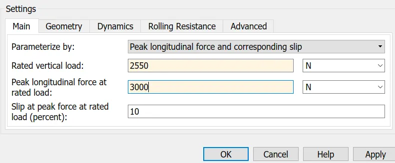
The vehicle body parameters are also considered as per the given standard values by Mahindra treo e-riksaw. The frontal area is calculated as per the given dimensions of the vehicle. The values considered are shown below:

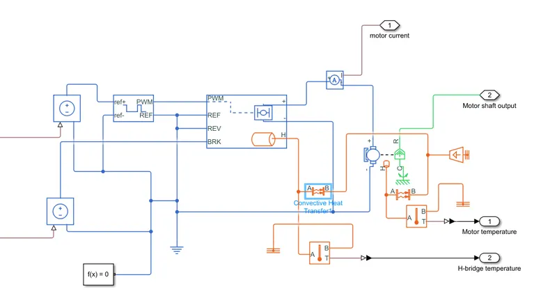
b) Motor and controller subsystem:
The dc motor block represents the electrical torque characteristics of the DC motor, that includes thermal port to sense the temperature of the motor. This block assumes that no electromagnetic energy is lost hence the back emf and torque constants have the same numerical value in SI units.
The motor controller will get the input from the longitudinal driver. Its tasks are to control the speed of the motor according to the input of the driver.
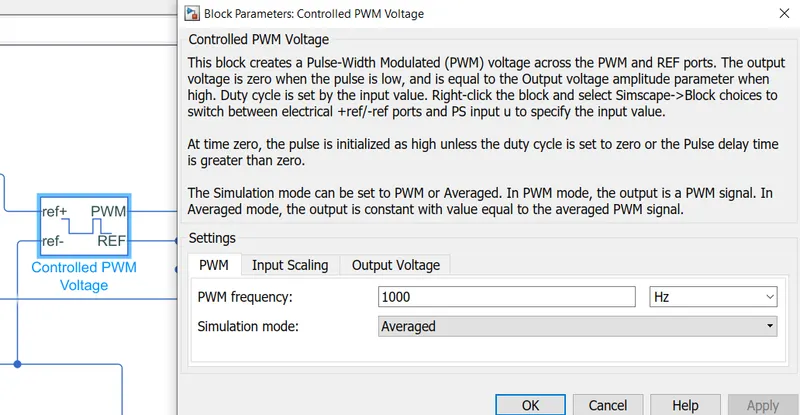
Acclerationa and decceleration commands are taken from the longitudinal driver block and it is given to the controlled voltage source block. Controlled PWM Voltage will generate the PWM signal in such a way that H-bridge generates the voltage to DC motor for the given driver input. Since all these components are of the simscape electrical category, they need a connection to the solver configuration block that helps to solve the simulation.
Controlled PWM Source:
This Block creates a Pulse width modulated voltage across PWM and REF ports. The output Voltage is zero when the pulse is low, and is equal to the Output Voltage amplitude parameter is high, and is equal to the Output Voltage amplitude parameter when high. Duty cycle is set by the input value. At the time zero, the pulse is initialized as high unless the duty cycle is set to zero or Pulse delay time is greater than zero.
Power converter:
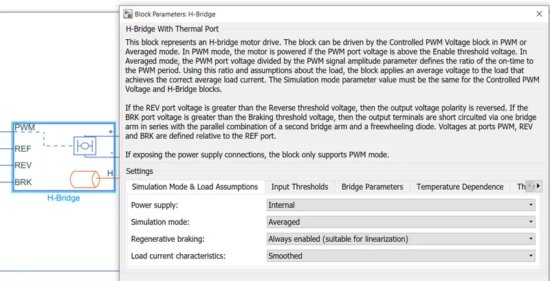
This block represents the H-Bridge motor drive. The block can be driven by the controlled voltage block in PWM or Averaged more. In PWM mode, the motor is powered if the PWM port voltage is above enabled threshold voltage.
In Averaged mode, The PWM port voltage is divided by the PWM signal amplitude parameter defines the ratio of the on-time to the PWM period. The simulation mode parameter value must be the same for controlled PWM voltage and H-bridge blocks.
Temperature Sensor:
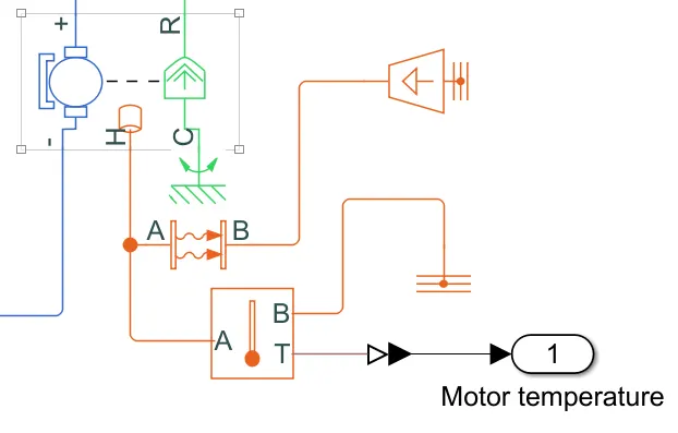
Used to measure the temperature of the H-bridge and Motor.
The physical port T reports the temperature difference across the sensor.
The Measurement is Positive when the temperature at A is Greater than at B.
Convective heat transfer block:
Since the motor generates a great amount of heat, the temperature is controlled by a forced convection through liquid cooling. A convective heat transfer block is added to achieve this. A convective heat transfer coefficient of 2000 W/m^2.K and a wetting area of approximately 0.025 m^2 on an average is considered. The ambient temperature is modelled as a temperature source block of a constant temperature of 300 K.
Other blocks:
|
Electrical Reference: Used to ground all electrical connections. |
Thermal Reference: Used to ground all the thermal connections. |
|
Mechanical Reference: Used to ground all the mechanical parts. |
Solver Configuration: Defines Solver settings for simulation. |
The final output of the motor as speed and torque is given through the motor shaft to the rear wheels.
The overall motor and the control system subsystem is shown below:
c) Battery and State of charge estimation:
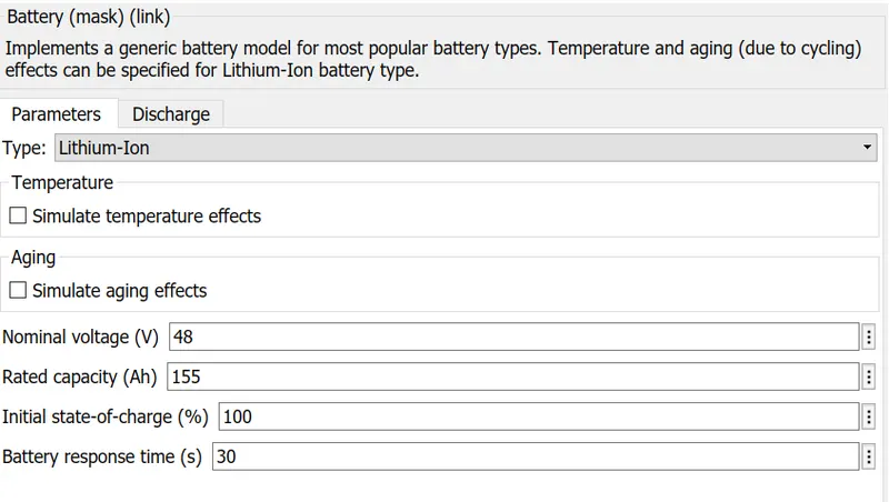
A nominal battery of 48V with a capacity of 7.37 Kwh(155 Ah) is considered as per the given parameter values for the e-rikshaw.
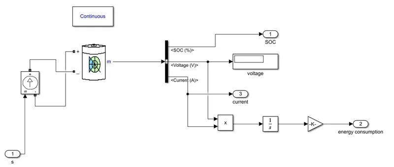
The battery has a positive and negative terminal which is given the voltage controlled source where the battery consumption is controlled by the motor controller and given to SOC block. State of Charge is the percentage of the battery level presents after certain travel or consumption of the battery charge by the vehicle. The majority of the blocks are simscape blocks where physical to simulink converter is used to convert the physical signal from simscape block to simulink signal.
The battery subsystem is shown below:
d) Driver controller:
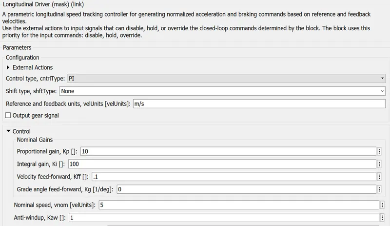
A speed tracking controller for generating normalized acceleration and braking commands based on reference and feedback velocities.Uses the external actions to input signals that can disable,hold,or override the close loop commands based on reference and feedback velocities. Drive cycle is connected to a longitudinal driver, having six ports namely Velocity reference, vehicle feedback,grade,info,acceleration,deceleration.
Vehicle reference is given by drive cycle data and Vehicle feedback is given by the output of the motor. These two will get the comparision of acceleration and deceleration output given to the motor controller. Accelerator command is given the PWM generator block and deceleration command is given to the regenerative braking. This block helps to generate the driver's conditions using the driver cycle block.
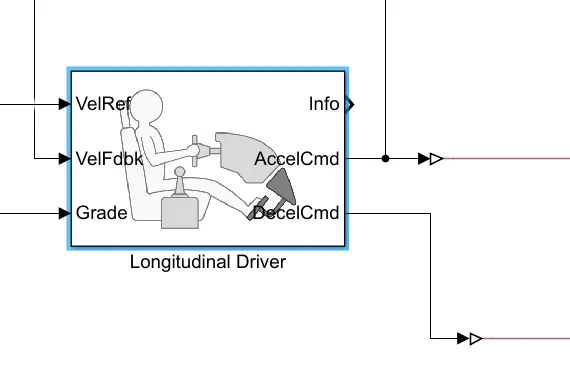
A reference velocity input that varies with time (drive cycles) is given as a velocity input as reference. Based on this reference, the vehicle's performance is evaluated by comparing the actual drive cycle with the vehicle's ability to track this drive cycle given the constraints.
The proportional and integral gains for the PI controller are tuned to get the optimal response.
The overall simulink model for the mahindra treo e-rikshaw is shown below:
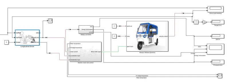
The output results tracked are the range, SOC,current, energy consumption and the motor and controller temperatures.
Results and discussions:
For three different drive cycles, calculate energy consumption, temperature rise of motor and controller.
1) Manual drive cycle:
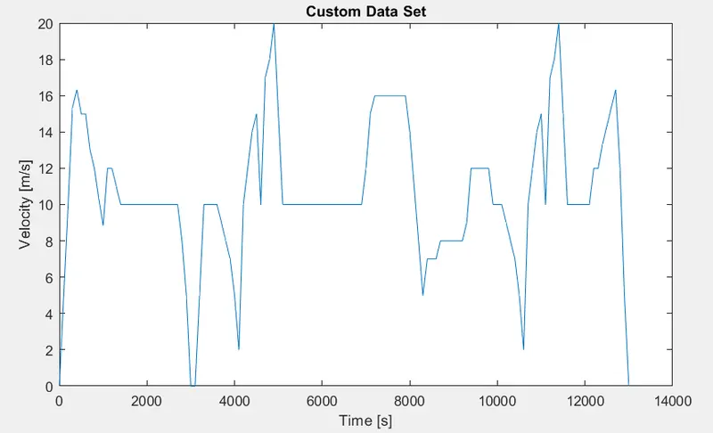
To verify the performance claim, a typical urban driving cycle is created manually. The drive cycle is created to simulate for approximately more than 3 hours. The chosen drive cycle is shown below:
The model is simulated for 11000 seconds (~ 3 hours). The SOC, energy consumption and the current plots are shown below:
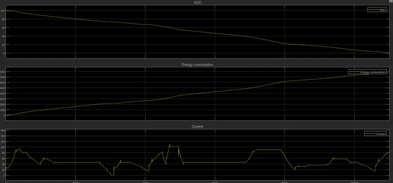
The results obtained are shown below:
| SOC | 0 |
| Energy Consumed | 7.831 kJ |
| Range | 113.8 km |
The mahindra treo claims to have approximately 130 km of range for a single full charge. The obtained simulation results for a typical urban drive cycle is approximately 113.8 km. This is a reasonable range when compared to the claimed range. The lower range may be a result of various friction losses and other assumptions that are made. The time taken for a complete discharge given the typical urban driving cycle is approximately 3 hours.
Temperature rise of motor and controller:
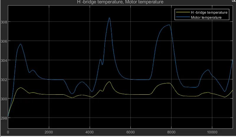
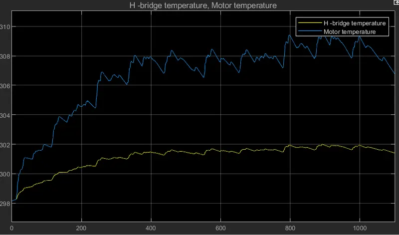
Notice that the temperature of the motor does not go beyond 309 degree Kelvin and that of H-bridge does not go beyond 302 degree kelvin. This is due to the fact that they are cooled by a liquid cooling system and heat is lost through convection. Hence, forced convection cooling is effective and helps to keep the temperatures within the limits.
2) Manhattan bus drive cycle:
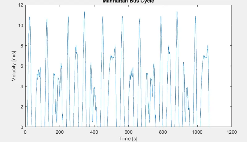
The plots for SOC, current and the energy consumption are shown:
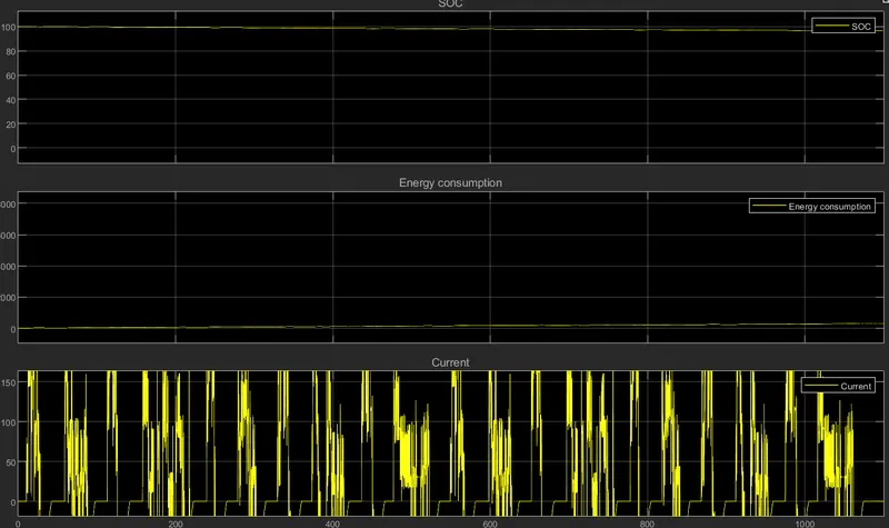
The battery SOC after 1100 seconds simulation is 96.49 %. The energy consumed 282.2 Joules. The total range is 3.423 km.
The drive cycle for the vehicle is shown below: Notice that the vehicle accurately follows the reference drive cycle.
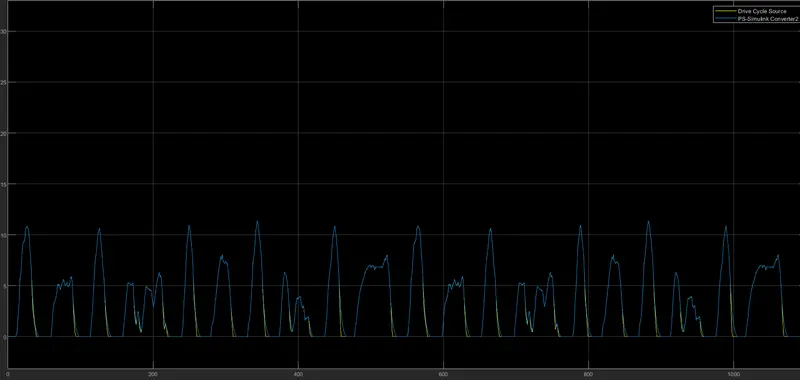
The temperature rise of the motor and controller are shown below. Since a convection heat transfer blocks are added to the motor and H-bridge, the temperature of motor is below 310 degree kelvin while that of H-bridge is below 302 degree kelvin.
3) Wide open throttle:
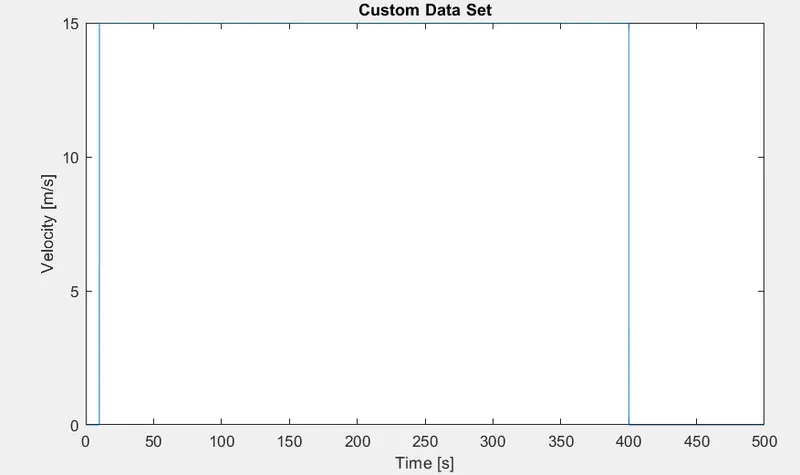
The plots for SOC, current and the energy consumption are shown:
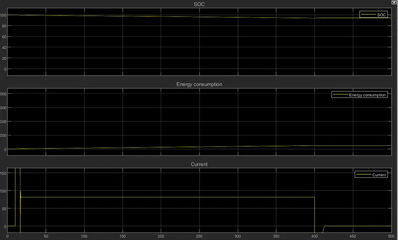
The SOC is 94.3 %. The energy consumed is 464 joules with a range of 5.865 km.
The temperature rise of motor and H-bridge drive is shown:
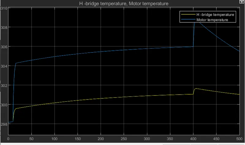
The maximum temperature od the motor is 309 degree kelvin while that of H-bridge is 302 degree kelvin.
Conclusions:
Electric e-riskaw is modelled using Matlab-simulink. The performance of the mahindra treo e-rikshaw is validated with the given parameters for a typical urban drive cycle. Forced convection heat transfer is considered for the cooling of motor and controller blocks. The performance parameters such as the state of charge, rangem energy consumed, motor and controller temperatures are evaluated for three different drive cycles.