Week-6 Challenge: EV Drivetrain
AIM:
1) To understand the types of power converter circuits are employed in electric and hybrid electric vehicle.
2) To determine steady speed of EV with duty cycle 70 %.
3) To explain the author's perspective in 'Induction Versus DC brushless motors by Wally Rippel, Tesla'
THEORY AND SOLUTION:
1) The general configuration of EV and HEV is shown below:
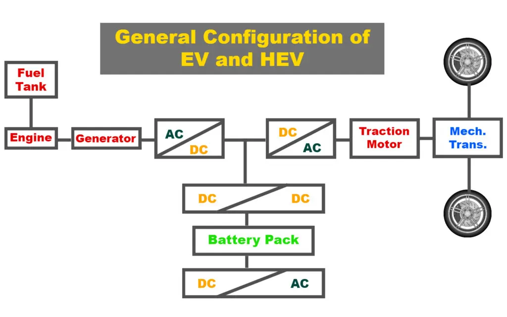
The main power converter circuits of an Electric Vehicle are DC-AC converters(inverters), AC-DC converters(rectifiers), DC-DC converters, battery, and electric motor. AC motors are used in HEVs or EVs for traction and they are fed by inverter and this inverter is fed by DC-DC converter which is connected to the battery pack. The function of power converters can be represented as below:
a) DC-DC converters (Choppers):
A DC/DC converter in its basic form converts unregulated DC input voltage at a certain level to a regulated DC output voltage at a different level with very high conversion efficiency.Transistors such as MOSFETs and IGBTs are used as switches. MOSFETs are preferred for high frequency, low and medium power applications, whereas IGBTs are preferred for low frequency high power applications. The switches are turned ON and OFF by pulse width modulation (PWM) technique.
The most commonly DC-DC converters used in an HEV or an EV are:
Unidirectional Converters:
They cater to various onboard loads such as sensors, controls, entertainment, utility and safety equipment.
Bidirectional Converters:
They are used in places where battery charging and regenerative braking is required. The power flow in a bi-directional converter is usually from a low voltage end such as battery or a supercapacitor to a high voltage side and is referred to as boost operation. During regenerative braking, the power flows back to the low voltage bus to recharge the batteries know as buck mode operation.
b) DC-AC converters (Inverters):
The most commonly used motors used in electric vehicles are 3 phase Induction Motors. These motors require AC supply to run at the desirable speeds. However, the ESS used in the vehicle stores DC power. Inverter is a power converter that converts this DC power into AC power required by the induction motors. The DC/AC inverter also performs the function of recharging the batteries during regenerative braking in HEVs. Inverters are generally classified into voltage-fed and current-fed types. Because of the need of a large series inductance to emulate a current source, current-fed inverters are seldom used for EV propulsion. In fact, voltage-fed inverters are almost exclusively used because they are very simple and can have power flow in either direction.
c) AC-DC power converters (Rectifiers):
In case of a Hybrid EV the AC power generated during by the generator needs to be converted into DC to be able to store it into the on-board Battery. In BEVs and HEVs both, the battery of the vehicle works on DC power. The utility provides AC supply and thus to charge the battery of the vehicle, a rectifier circuit has to be used to convert this grid supply into the DC supply required by the battery.
2)
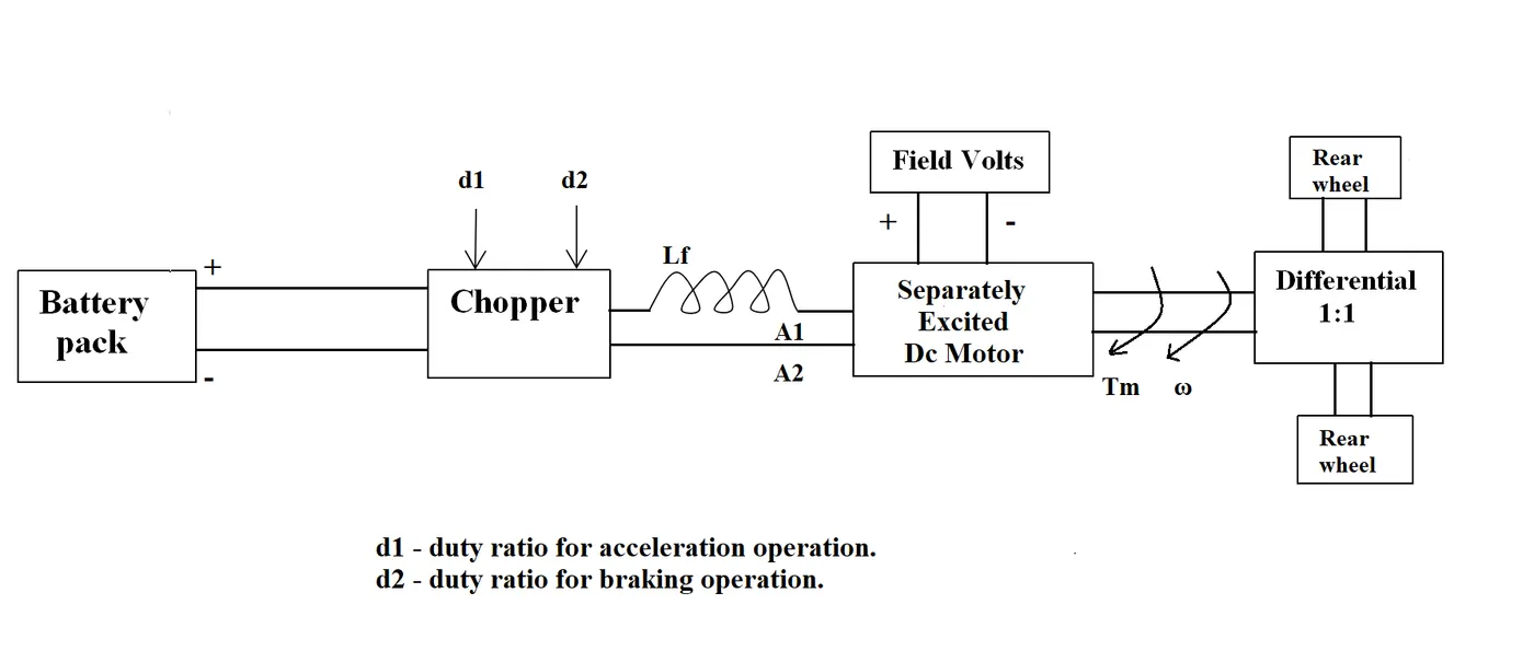
Given: Rated Armature voltage= 72 V; Rated armature current= 400 A; Ra= 0.5Ω; KΦ= 0.7 Volt second
Chopper Switching frequency= 400 Hz
The vehicle speed-torque characteristics are given by the below equation

Since the duty cycle of the vehicle is 70 %, the actual voltage supplied to the motor is given as:
V= 72 * 0.7 = 50.4 Volts
The torque-speed characteristics of the motor is given as:
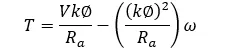
Substitute V =50.4, Ra=0.5, KΦ= 0.7 into the above equation to get:
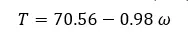
The vehicle operated at a condition where the speed-torque characteristics of motor matches with that of the vehicle, Hence:
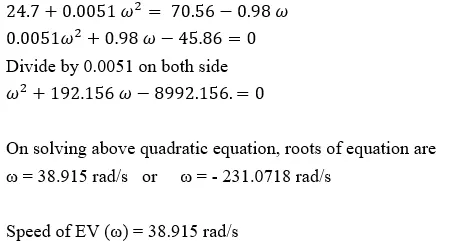
3)
In this blog, the author compares the features of the Induction Motors and Brushless DC Motors and after detailed discussion, concludes around the point that DC brushless drives will dominate in the hybrid and coming plug-in hybrid markets, and that induction drives will be used in high-performance pure electric vehicles. The constructional difference between the two motors is between their rotors, the stators having almost similar construction. The rotor of the Brushless DC motor has permanent magnets and the interaction between the stator magnetic field and the rotor magnetic fields produce the required torque. The author focuses on the point that, to produce the variable stator magnetic field the current control required is provided by the inverter.
The rotor of the induction motor has a squirrel cage type of construction and is self-starting. Thus the induction motor requires less ancillary equipment and can directly be connected to the utility supply.The heat generated in the rotor is less, power factor (higher peak operating point), efficiency is better in BLDCs. On the other hand, since these motors have permanent magnet rotors, the magnetic field strength is constant and there is no scope for minimization of losses. These issues can be very effectively addressed in the induction motor drives, where the magnetic field is proportional to V/f. Thus, optimum efficiency can be maintained minimizing the losses. With an increasing rating, this factor proves advantageous for the average efficiency of the IM because BLDC drives cannot really control the amount of power lost.
The author adresses the drawbacks of induction motors that they cannot operate on DC, also when operated from utility power, they have limited starting torque and somewhat limited running peak torque capabilities as shaft speed is proportionate to line frequency. He mentions some advantages of dc brushless drive like less rotor heat is generated and they also operate at unity power factor.