Week 8 - BlockMesh Drill down challenge
AIM:1) Case setup and simulation of an incompressible-laminar-viscous flow through the backward facing step geometry using Open FOAM
2) Changing the block mesh parameter grading factor and then comparing the results.
PROCEDURE:
1) To setup and run a tutorial case in openFOAM, open the tutorial folder using the linux terminal.
2) Change the directory to the 'cavity' through 'incompressible' and then through 'icoFOAM'.
3) Copy the 'cavity' folder into the $FOAM_RUN folder where the case setup and simulation are run.
4) Come back to the cavity folder inside the $FOAM_RUN and then open 'system' folder inside the cavity.
5) Four different files namely blockMeshDict, controlDict, fvSchemes, fvSolution appear
where the code can be modified according to the requirements such as boundary conditions and other simulation parameters.
The labelling of the vertices for the model is shown:
Grading factor: It defines the mesh stretching. It is defined by the formula:
GF= size of the last cell / size of the first cell.
A GF of 1 represents that the mesh is uniform and all the cell sizes are same. A GF of 0.2 represents that the first cell is 5 times larger than that of the final cell.
Modified BlockMeshDict file accordinf to the geometry given:
/*--------------------------------*- C++ -*----------------------------------*\
  =========                 |
  \\      /  F ield         | OpenFOAM: The Open Source CFD Toolbox
   \\    /   O peration     | Website:  https://openfoam.org
    \\  /    A nd           | Version:  8
     \\/     M anipulation  |
\*---------------------------------------------------------------------------*/
FoamFile
{
    version     2.0;
    format      ascii;
    class       dictionary;
    object      blockMeshDict;
}
// * * * * * * * * * * * * * * * * * * * * * * * * * * * * * * * * * * * * * //

convertToMeters 0.01;

vertices
(
    (0 0 0)
    (8 0 0)
    (8 0.5 0)
    (0 0.5 0)
    (8 1 0)
    (0 1 0)
    (20 1 0)
    (20 0.5 0)
    (20 0 0)
    (20 -1 0)
    (8 -1 0)
    (0 0 0.1)
    (8 0 0.1)
    (8 0.5 0.1)
    (0 0.5 0.1)
    (8 1 0.1)
    (0 1 0.1)
    (20 1 0.1)
    (20 0.5 0.1)
    (20 0 0.1)
    (20 -1 0.1)
    (8 -1 0.1)

);

blocks
(
    hex (0 1 2 3 11 12 13 14) (200 10 1) simpleGrading (1 1 1)
    hex (3 2 4 5 14 13 15 16) (200 10 1) simpleGrading (1 1 1)
    hex (2 7 6 4 13 18 17 15) (200 10 1) simpleGrading (1 1 1)
    hex (1 8 7 2 12 19 18 13) (200 10 1) simpleGrading (1 1 1)
    hex (10 9 8 1 21 20 19 12) (200 10 1) simpleGrading (1 1 1)
);

edges
(
);

boundary
(
    inlet
    {
        type patch;
        faces
        (
            (0 11 14 3)
            (3 14 16 5)
        );
    }
    outlet
    {
        type patch;
        faces
        (
            (9 8 19 20)
            (8 7 18 19)
            (7 6 17 18)
        );
    }
    frontAndBack
    {
        type empty;
        faces
        (
            (0 3 2 1)
            (3 5 4 2)
            (10 1 8 9)
            (1 2 7 8)
            (2 4 6 7)
            (11 12 13 14)
            (14 13 15 16)
            (13 18 17 15)

            (12 19 18 13)
            (21 20 19 12)

        );
    }
    Noslipwalls
    {
         type wall;
         faces
        (
         	(5 16 15 4)
        	(4 15 17 6)
        	(0 1 12 11)
       	(10 21 12 1)
        	(10 9 20 21)
        );
    }

);

mergePatchPairs
(
);

// ************************************************************************* //
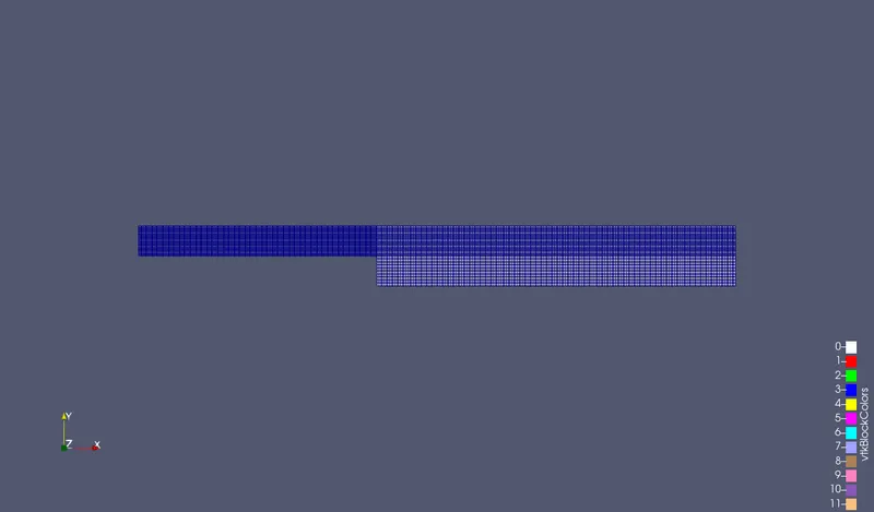
The geometry can now be viewed using the paraview using paraFoam command.
The geometry is as shown:
The pressure and velocity initial conditions need to be specified by editing the corresponding files:
Pressure initial conditions:
/*--------------------------------*- C++ -*----------------------------------*\
  =========                 |
  \\      /  F ield         | OpenFOAM: The Open Source CFD Toolbox
   \\    /   O peration     | Website:  https://openfoam.org
    \\  /    A nd           | Version:  8
     \\/     M anipulation  |
\*---------------------------------------------------------------------------*/
FoamFile
{
    version     2.0;
    format      ascii;
    class       volScalarField;
    object      p;
}
// * * * * * * * * * * * * * * * * * * * * * * * * * * * * * * * * * * * * * //

dimensions      [0 2 -2 0 0 0 0];

internalField   uniform 0;

boundaryField
{

	inlet
    {
        type            zeroGradient;
     }

       outlet
    {
	type            fixedValue;
	value 	         uniform 0;
     }


    Noslipwalls
    {
        type            zeroGradient;
    }

    frontAndback
    {
        type            empty;
    }


}

// ************************************************************************* //
Velocity initial conditions:
/*--------------------------------*- C++ -*----------------------------------*\
  =========                 |
  \\      /  F ield         | OpenFOAM: The Open Source CFD Toolbox
   \\    /   O peration     | Website:  https://openfoam.org
    \\  /    A nd           | Version:  8
     \\/     M anipulation  |
\*---------------------------------------------------------------------------*/
FoamFile
{
    version     2.0;
    format      ascii;
    class       volVectorField;
    object      U;
}
// * * * * * * * * * * * * * * * * * * * * * * * * * * * * * * * * * * * * * //

dimensions      [0 1 -1 0 0 0 0];

internalField   uniform (0 0 0);

boundaryField
{

	inlet
     {
	type             fixedValue;
	value		  uniform (1 0 0);
     }

     outlet
     {
     	type             zeroGradient;
     }


    Noslipwalls
    {
        type            noSlip;
    }

    frontAndBack
    {
        type            empty;
    }
}

// ************************************************************************* //
RESULTS:
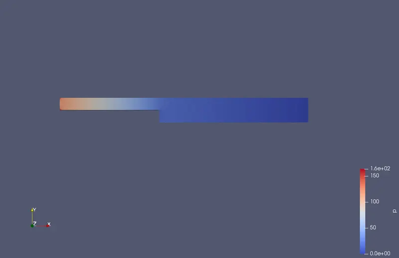
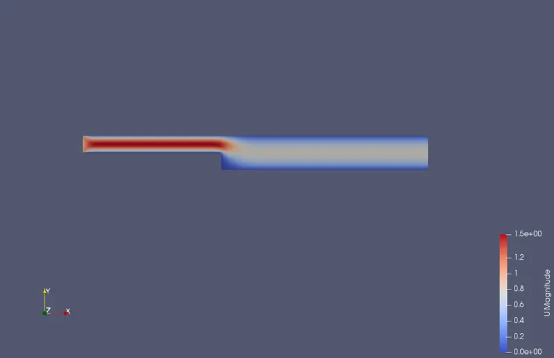
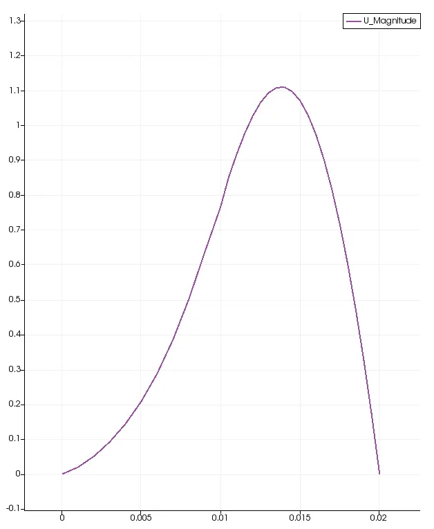
Case 1) For a grading factor of 1:
The pressure field is shown after 0.5 seconds:
The velocity field is shown below:
The velocity profile line at 0.085 m from the intlet is shown below:
case 2: with grading factor of 0.2:
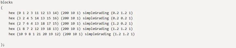
The code has to be modified only inside the blocks section in the blockMesh dict file.
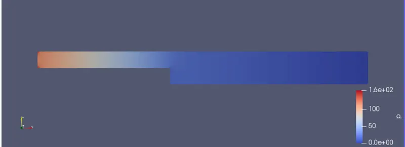
The pressure profile is shown below:
The velocity profile is shown:
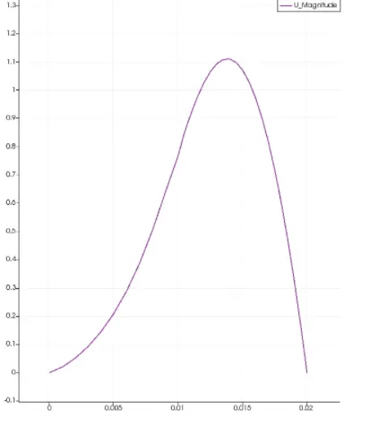
The velocity profile at 0.085 m from the inlet is shown:
Effect of grading factor on the results:
1) Comparing the results with the grading factor of 1 and 0.2, even though the plots appear similar, the maximum values for the pressure and velocity in both the cases seem to be slightly different.
2) The maximum velocities with GF of 1 and 0.2 are found to be respectively 1.6705 and 1.6748 respectively.
3) the simulation run time for the case for GF of 0.2 is less than that of the case with GF of 1.
4)Since the growth factor affects the number of cells in the domain, it affects the accuracy of the results.