Week-7 Challenge: DC Motor Control
AIM:
- To run the MATLAB demo script “Speed Control of DC Motor using BJT H-Bridge” & evaluate the model such that Armature current doesn’t shoot-up when the Motor changes its direction of rotation.
- To develop a 2-Quadrant Chopper DC Drive
- To explain about the BLDC motor
Introduction:
Power electronics is the application of solid-state electronics to the control and conversion of electric power.
In modern systems, the conversion is performed with semiconductor switching devices such as diodes, thyristors, and power transistors such as the power MOSFET, BJT and IGBT. The power range in these transsitors typically vary from tens of watts to several hundred watts. In industry a common application is the variable speed drive (VSD) that is used to control an induction motor. The power range of VSDs start from a few hundred watts and end at tens of megawatts.
Power Modules/Switches:
When it comes to EV application, controlling the Speed of the Motor mainly depends on controlling the Voltage & Current flowing to the Motor. To ensure a rotating field in the motor continuously, flux has to be switched continuously by controlling the direction and timing of the Current in to the coil. In order to achieve this Controllers/Inverters are used to adjust the Voltage in the coil and to control the magnitude of current.
PWM (Pulse Width Modulation) is the technique incorporated in Power switches which alters the Voltage level by lengthening or reducing the Pulse ON time.
A) The below simulink model shows the simulation of an H-bridge used to generate a chopped voltage and to control the speed of a DC motor.
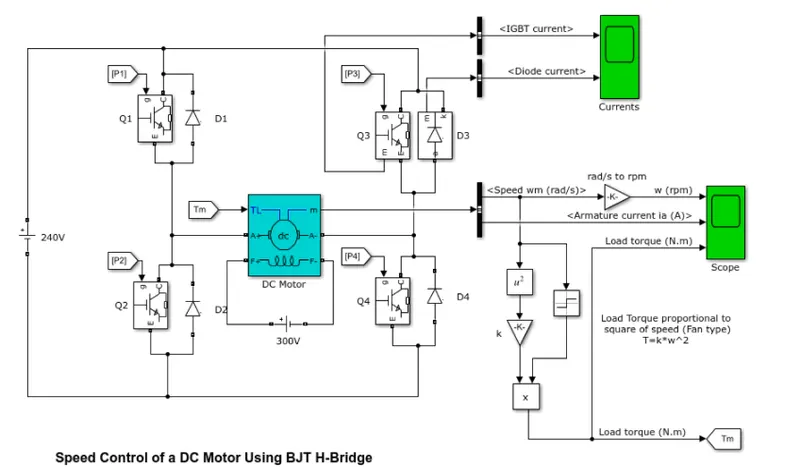
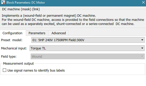
The Bipolar Junction Transistor (BJT) when used for power switching applications, operates as an IGBT. When it is conducting (BJT operating in the saturated region), a forward voltage Vf is developed between collector and emitter (in the range of 1 V). Therefore, the IGBT block can be used to model the BJT device. The IGBT block does not simulate the gate current controlling the BJT or IGBT. The switch is controlled by a Simulink® signal (1/0). The DC motor uses the pre-set model (5 HP 24V 1750 rpm). It simulates a fan type load (where Load torque is proportional to square of speed). The armature mean voltage can be varied from 0 to 240 V when the duty cycle (specified in the Pulse Generator block) is varied from 0 to 100%.
The H-bridge consists of four BJT/Diode pairs (BJT simulated by IGBT models). Two transistors are switched simultaneously: Q1 and Q4 or Q2 and Q3. When Q1 and Q4 are fired, a positive voltage is applied to the motor and diodes D2-D3 operate as free-wheeling diodes when Q1 and Q4 are switched off. When Q2 and Q3 are fired, a negative voltage is applied to the motor and diodes D1-D4 operate as free-wheeling diodes when Q2 and Q3 are switched off.
The motor parameters are given as:
- Power = 5 HP
- Rated Voltage = 240 V
- Rated Speed = 1750 RPM
The plots obtained are as shown below:
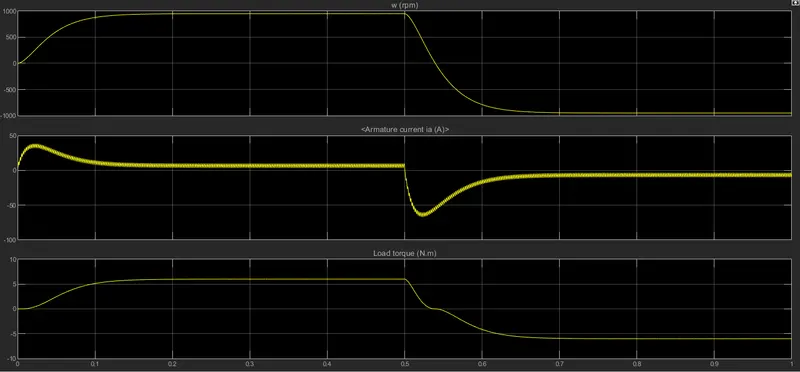
Plot 1 from above figure shows the Motor Speed against time. Notice that the speed of the motor is proportional to the torque. The maximum speed achieved by the motor is approximately 950 rpm.
B) Plot 2 shows the Armature Current drawn at each instant. Notice that initially the current shoots up and then becomes constant for 0.5 seconds. After 0.5 seconds, the current is reversed and there is a second shoot up in the current in the reverse direction.
In a motor, armature current (I) is given by:
I=(V-E)/R
Here V is the voltage applied, E is the back EMF and R is the resistance of the armature coil.
Initially, the speed of the motor is 0, hence there is no back emf generated, hence the current in the aramture coil will be V/R. As the rotor starts rotating, back emf slowly increases, hence the overall current decreases and then becomes constant.
C) Comparison of 4-Quadrant Chopper DC Drive (DC7) block with BJT H-Bridge Model.
The Four-Quadrant Chopper DC Drive (DC7) block represents a four-quadrant, DC-supplied, chopper (or DC-DC PWM converter) drive for DC motors. This drive features closed-loop speed control with four-quadrant operation. The speed control loop outputs the reference armature current of the machine. Using a PI current controller, the chopper duty cycle corresponding to the commanded armature current is derived. This duty cycle is then compared with a sawtooth carrier signal to obtain the required PWM signals for the chopper. This drive can operate in all four quadrants (forward motoring, reverse regeneration, reverse motoring, and forward regeneration).
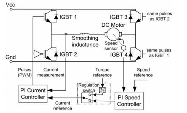
Comparison with H-Bridge Model
The machine is separately excited with a constant DC field voltage source. There is thus no field voltage control. By default, the field current is set to its steady-state value when a simulation is started.
The armature voltage is provided by an IGBT converter controlled by two PI regulators. The converter is fed by a constant DC voltage source. Armature current oscillations are reduced by a smoothing inductance connected in series with the armature circuit.
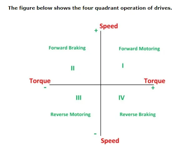
In the I quadrant power developed is positive and the machine is working as a motor supplying mechanical energy. The I (first) quadrant operation is called Forward Motoring. II (second) quadrant operation is known as Braking. In this quadrant the direction of rotation is positive, and the torque is negative, and thus, the machine operates as a generator developing a negative torque, which opposes the motion. The kinetic energy of the rotating parts is available as electrical energy which may be supplied back to the mains. In dynamic braking dissipated the energy is dissipated in the resistance. The III (third) quadrant operation is known as the reverse motoring. The motor works, in the reverse direction. Both the speed and the torque have negative values while the power is positive. In the IV (fourth) quadrant, the torque is positive, and the speed is negative. This quadrant corresponds to braking in the reverse motoring mode.
2) 2 quadrant chopper:
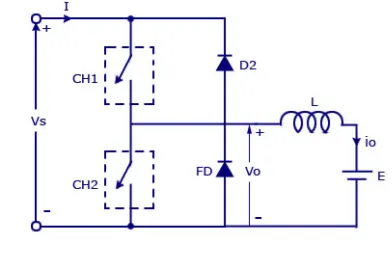
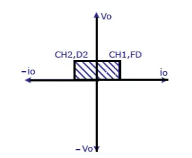
In this type of Chopper, the average voltage will be always positive but the average load current might be positive or negative. The two Switches CH1 and CH2 should not be turned on simultaneously as the combined action may cause a short circuit in supply lines. For regenerative braking and motoring these type of chopper configuration is used.
We will always get a positive output voltage V0 as the freewheeling diode FD is present across the load. When the chopper CH1 is on the current flows from source to load. The inductor stores energy. When Ch1 turn OFF the freewheeling diode starts conducting and the output voltage v0 will be equal to Vs. The direction of the load current i0 will be reversed. The current i0 will be flowing towards the source. The load current will be negative when the CH2 is on. The current completes its path through diode D2.
3) BLDC motors and thier working:
Brushless DC motors are common in industrial applications across the world. Brushless DC motors, as you may imagine, do not contain brushes and use a DC current. In this motor, the permanent magnets are attached to the rotor. The current-carrying conductors or armature windings are located on the stator. They use electrical commutation to convert electrical energy into mechanical energy. A BLDC Motor is a type of synchronous motor in the sense that the magnetic field generated by the stator and the rotor revolve at the same frequency.
In BLDC permanent magnets are attached in the rotor and move the electromagnets to the stator. The high power transistors are used to activate electromagnets for the shaft turns. The controller performs power distribution by using a solid-state circuit.