Week 4 - CHT Analysis on Exhaust port
AIM:
- Describe why and where a Conjugate Heat Transfer analysis is used.
- Perform a CHT analysis on exaust manifold with 2 different sizes of mesh and compare the results and plots of velcoty, temperature and heat transfer coefficient.
- How to verify if the HTC predictions from the simulations are right and On what factors does the accuracy of the prediction depend on.
The term 'conjugate heat transfer' refers to a heat transfer process involving an interaction of conduction within a solid body and the convection from the solid surface to fluid moving over the solid surface. There exists heat transfer between Solid and Fluid domains by exchanging thermal energy at the interfaces between them. It requires a multiregion mesh to have a clear definition of the interfaces in the computational domain. Such a mesh can be created with the Hex-dominant parametric operation in the mesh creator.
The physical processes and solutions of the governing equations are considered separately for each object in two subdomains. Matching conditions for these solutions at the interface provide the distributions of temperature and heat flux along the body–flow interface. The CHT approach has an advantage over FE thermal analyses in that wall heat transfer coefficients and their local variations on surfaces are directly calculated within the model rather than based on simplified empirical calculations. The CHT approach therefore has benefits for those applications where heat transfer is either non-uniform or difficult to calculate empirically.
Typical applications of this analysis type is the simulation of heat exchangers, cooling of electronic equipment, and general-purpose cooling and heating systems.
Modelling of CHT analysis of an exhaust manifold using ANSYS:
Geometry :-
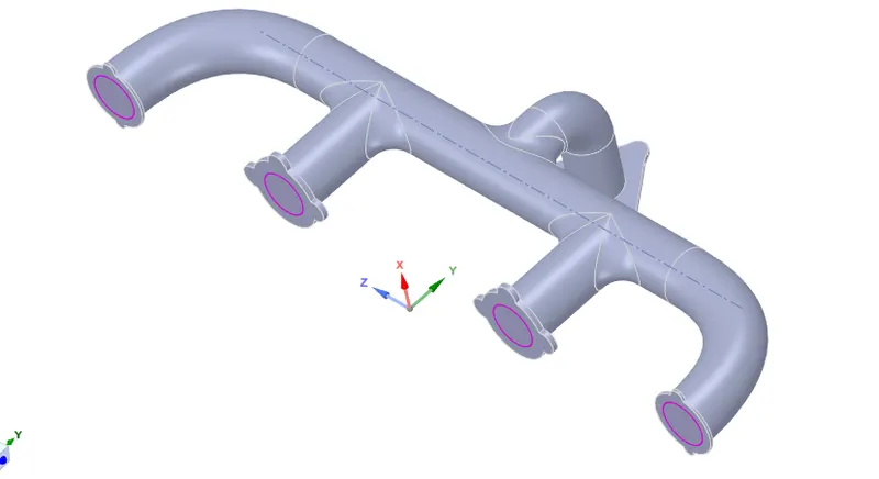
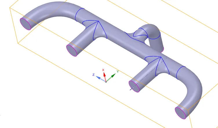
For the geometry shown, the fluid volume is extracted using ANSYS spaceclaim and the outer covering is the solid body where CHT takes place from fluid to solid body.
The fluid volume is shown below:
MESHING:
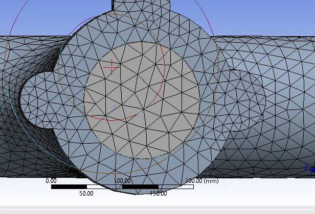
Make sure that share topology share is ON, so the mesh created between solid and fluid region share its edges and other features between them.
Case I : Base mesh
For this case we go through the default mesh generated by ANSYS. The mesh generated for the solid and the fluid region is continuous since the topology is shared between two volumes.
- Element size = default (150 mm)

The generated mesh is shown below:
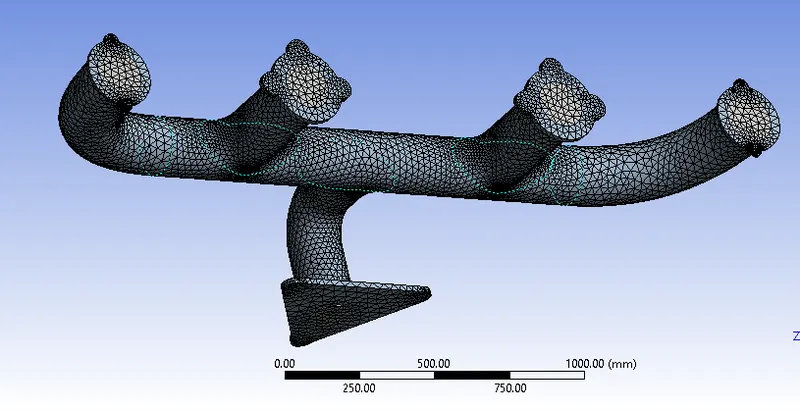
Notice that the mesh is continuos and shared between the fluid and solid regions as shown below:
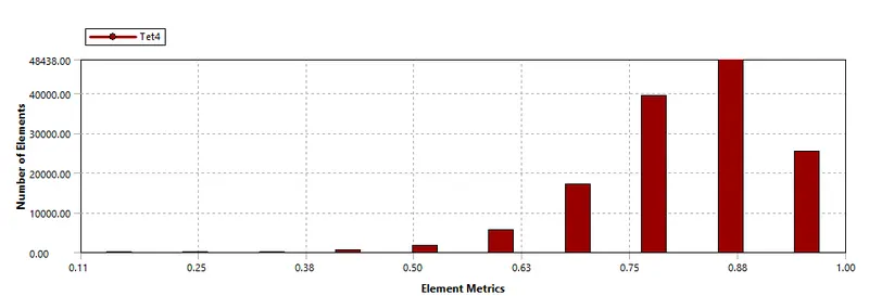
The element quality metrics are shown:
-
Case II : Refined mesh
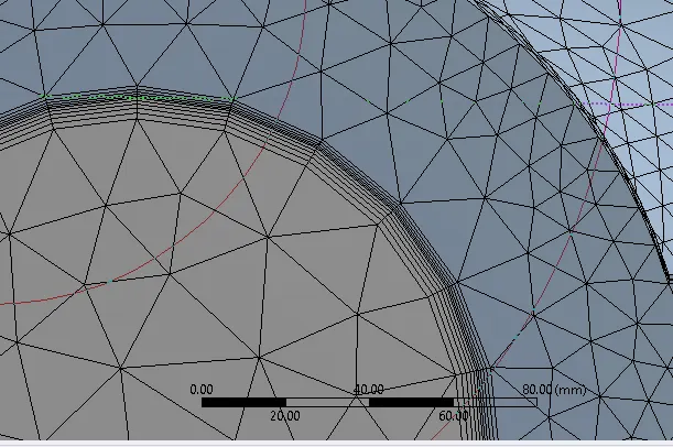
To obtain more accurate results, the mesh is refined with added inflation layers. The heat transfer coefficient values can be accurately calculated at the surface between solid and fluid volumes with added inflation layers.
For the solid volume, an element size of 10 mm is chosen to refine the mesh.
Inflation layer is provided at the interface between solid and fluid with a total inflation thickness of 5 mm and growth rate of 1.2.
- The inflation layers are as shown below:

Physics Setup to run the simulation:
A pressure based solver is used with the steady state simulation. The energy equation is turned on since the temperature distribution needs to be calculated. The standard k-epsilon turbulence model is chosen.
Materials :-
Fluid Flow inside the domain : Air
Solid material Outside : Aluminum
Boundary conditions :-
Inlet :
- Type - Velocity
- velocity - 5 m/s
- Temperature - 700 K.
Outlet:
- Type - Pressure
- Pressure - Gauge pressure (0 Pa)
Outer wall :
- Type - Wall
- Thermal conditions - Convection
- Heat transfer coefficient - 20 W/m^2.K
Plots and Results:
Baseline mesh plots for different variables:
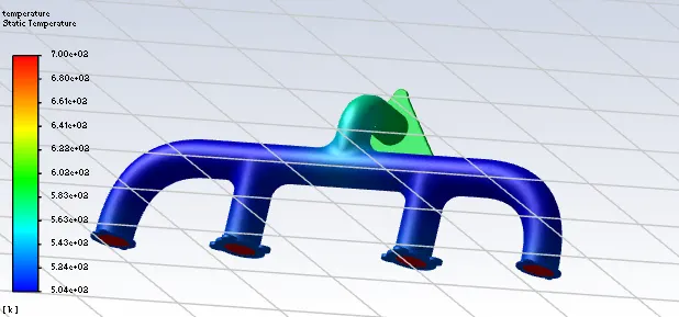
The temperature contours are shown:
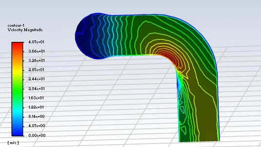
The velocity contours are shown near the exhaust port:
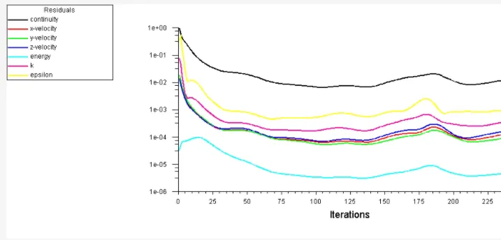
The residual plot is shown:
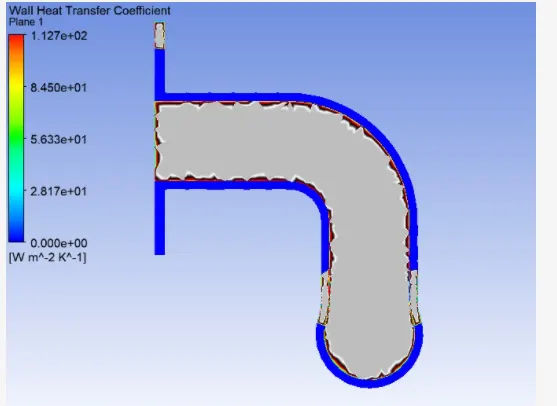
Heat transfer coefficient plot near the walls is shown below: Notice that since there are no inflation layers, the plot is not smooth.
Case 2: Refined mesh with inflation layers at the surface separating fluid and solid:
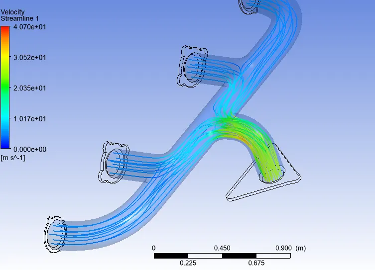
The velocity streamlines inside the fluid region are shown below. Notice that the velocity at the exhaust port is higher than that of inlet ports beacuse of mass conservation.
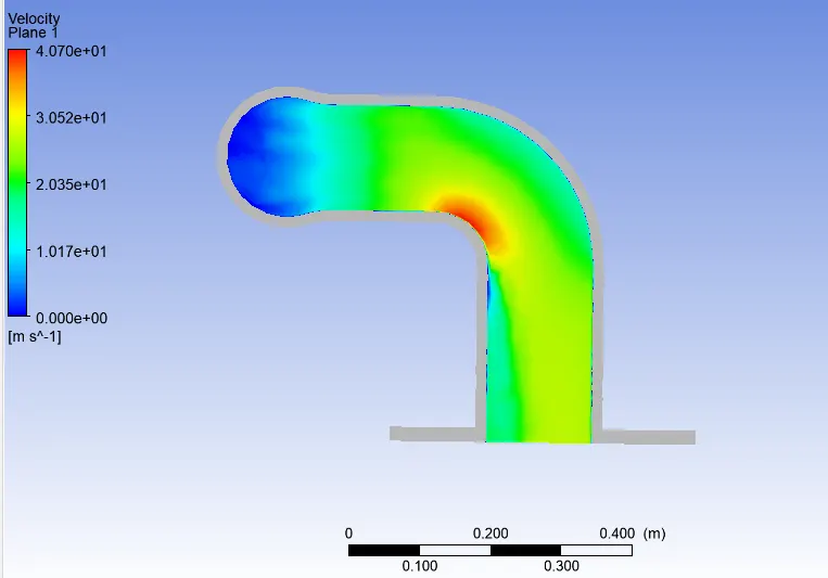
The velocity plot in the exhaust port is shown below. Notice that the highest velocity is attained at the bend.
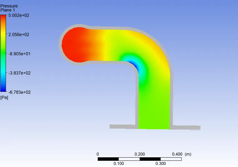
The pressure plot is shown below:
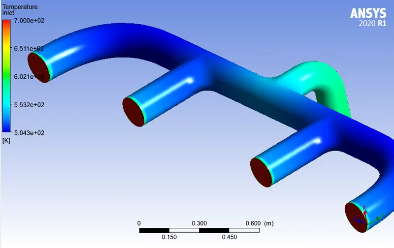
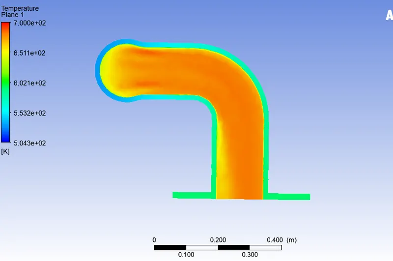
The temperature over the domain and the exhaust port are shown:
The plot of wall heat transfer coefficient is shown below:
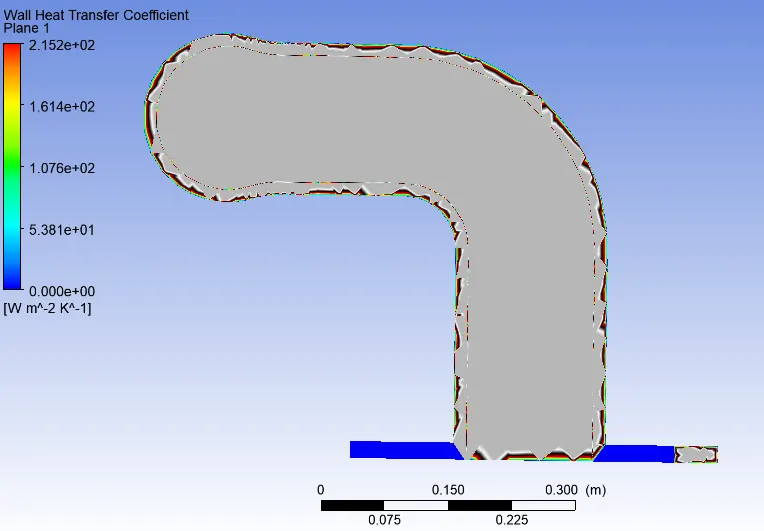
With the inflation layers, notice that the wall heat transfer coefficient is captured accruately along the surface separating the solid and fluid volumes. The maximum heat transfer coefficient is obtained at the same location where there is maximum velocity.
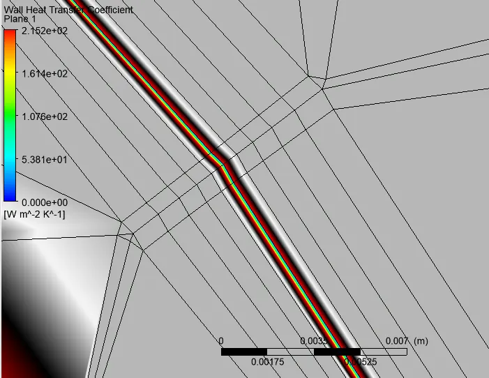
The maximum heat transfer coefficient for the baseline mesh is found to be approximately 112 whereas that for the refined mesh with inflation layers is approximately 215 Wm^-2 k^-1.
Verification of accuracy of Heat Transfer Coefficient results from simulaiton:
Verification of HTC predections from the simulation can be done in following ways:
1. By numerical way. It can be done by calculating Nusselts number and heat transfer coefficient and comparing with the results obtained from the simulation.

where,
h = convective heat transfer coefficient of the flow
L = characteristic length
k = thermal conductivity of the fluid.
For free convection, the average Nusselt number is expressed as a function of the Rayleigh number and the Prandtl number, written as:

Otherwise, for forced convection, the Nusselt number is generally a function of the Reynolds nuumber and the Prandtl number, written as:

2. By experimental analysis, the experiment should be conducted for the simulation done and by compairing both output results, validation of performed analysis can be done.
Factors on which prediction accuracy depends:
1. Meshing the geometry with finer mesh as much as possible and Inflation layer must be given wherever required.
2. Topology for the different volumes must be shared in the geometry for node to node coneection in meshing which will be responsible for more accurate results.
3. Selection of solution models, methodology etc also affect the precition accuracy.
CONCLUSIONS:
- As seen from the Post processing plots,the maximum velocity and heat transfer coefficient values are high in the Refined case.
- The velocity tends to increase from the inlet to the outlet because of mass conservation and mixing of air. hence, the high heat transfer coefficient at the junction is due to that high velocity and also when transfer of heat from fluid to solid is high.
- The internal flow velocity and its characteristics are affected by the Initial velocity, Pressure, the physical features of the geometry etc. that affect the heat transfer rates and hence CHT analysis is essential prior experimental analysis for better prediction life of the designed component.
- As shown in the plots, the hot exhaust gases passing through the manifold transfer some of the heat to it via convection. The amount of heat transfer can be related directly with the velocity of the exhaust. The temperature is lower where the flow is stagnate or is moving at the inlet velocity. As the velocity increases, so does the Reynolds number and hence the amount of heat transferred.
- Best methods to predict the accuacy of the result is by comparing the nusselt numbers from experiments and numerical results. The other method to verify is by comparing the results from published experimental results.