Week 8 - Simulating Cyclone separator with Discrete Phase Modelling
Aim:- To perform analysis on cyclone separator and calculate the separation efficiency and pressure drop.
Objective:-
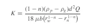
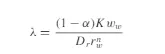
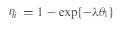
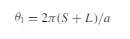
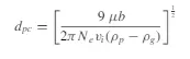
- To write a few words about any four empirical models used to calculate the cyclone separator efficiency.
- To perform an analysis on a given cyclone separator model by varying the particle diameter from 1 μm to 5 μm and calculate the separation efficiency in each case. Discuss the results. [Use both the velocity's as 3m/sec.]
- To perform an analysis on a given cyclone separator model by varying the particle velocity from 1 m/sec to 5 m/sec and calculate the separation efficiency and pressure drop in each case.
THEORY:
Cyclone separators or simply cyclones are separation devices that use the principle of inertia to remove particulate matter from flue gases. Cyclone separators is one of many air pollution control devices known as precleaners since they generally remove larger pieces of particulate matter.
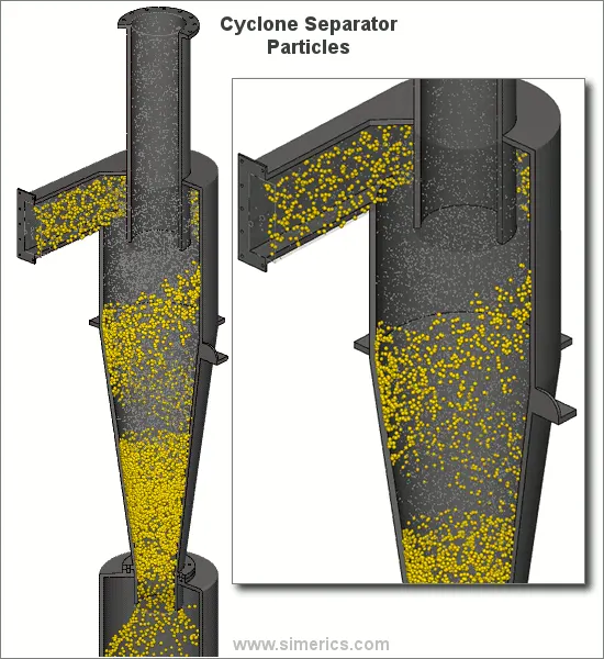
Principle and Working:
A high speed rotating (air)flow is established within a cylindrical or conical container called a cyclone. Air flows in a spiral pattern, beginning at the top (wide end) of the cyclone and ending at the bottom (narrow) end before exiting the cyclone in a straight stream through the center of the cyclone and out the top. Larger (denser) particles in the rotating stream have too much inertia to follow the tight curve of the stream and strike the outside wall, falling then to the bottom of the cyclone where they can be removed. In a conical system, as the rotating flow moves towards the narrow end of the cyclone the rotational radius of the stream is reduced, separating smaller and smaller particles.
Applications:
General applications include:
_ oil refineries to separate oils and gases
_ cement industry
_vacuum cleaners
Effectiveness
Cyclone separators are generally able to remove somewhere between 50-99% of all particulate matter in the flue gas. How well the cyclone separators are actually able to remove this matter depends largely on particle size. If there is a large amount of lighter particulate matter, fewer of these par0ticles are able to be separated out. Because of this, cyclone separators work best on flue gases that contain large amounts of big particulate matter.
There are several advantages and disadvantages to using cyclone separators. First, cyclone separators are beneficial because they are not expensive to install or maintain, and they have no moving parts. This keeps maintenance and operating costs low. Second, the removed particulate matter is collected when dry, which makes it easier to dispose of. Finally, these units take up very little space. Although effective, there are also disadvantages in using cyclone separators. Mainly because the standard models are not able to collect particulate matter that is smaller than 10 micrometers effectively and the machines are unable to handle sticky or tacky materials well.
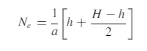
Empirical models used to calculate the cyclone separator efficiency
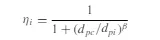

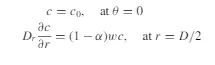
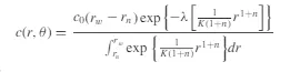
Where,
 and,
and,
Model setup and analysis:
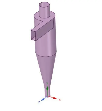
A cyclone seperator model is shown below. The edges of inlet and outlets are chosen and the fluid volume is extracted from the model.
MESHING:
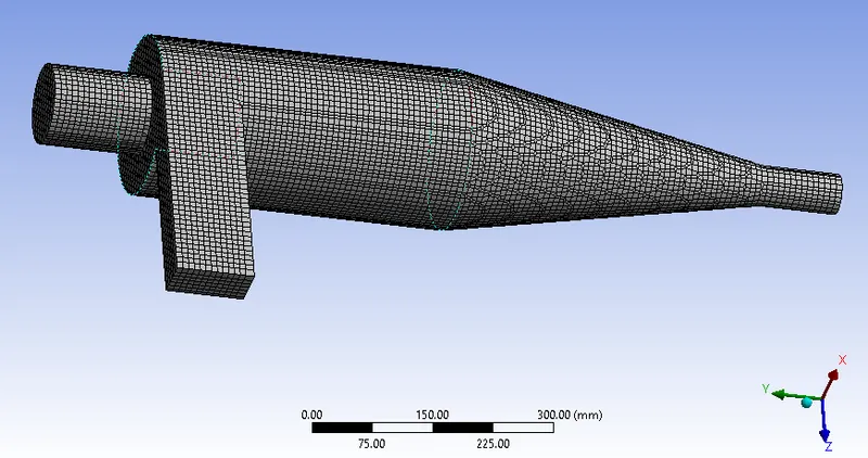
A body fitted cartesian mesh with global element size of 10mm is chosen for the model.
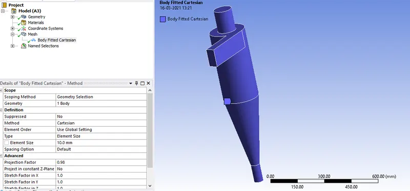
The generated mesh is shown below:

Solver setup:
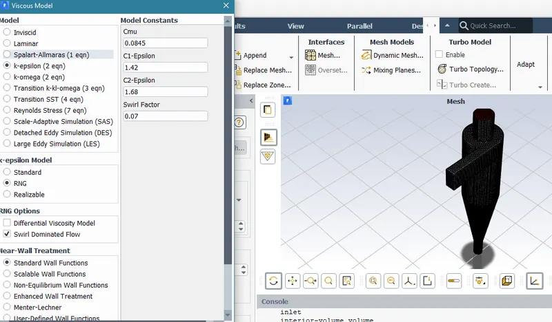
A RNG k-epsilon model with swirl dominated flow is chosen for this simulation as RNG model captures the swirl flows more accurately.
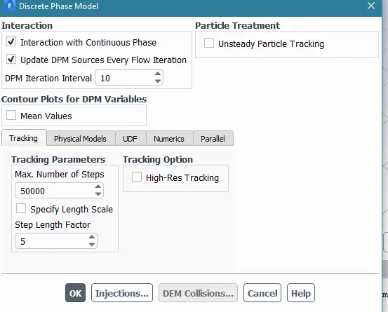
A discrete phase model is chosen with anthracite particles as solid phase particles.
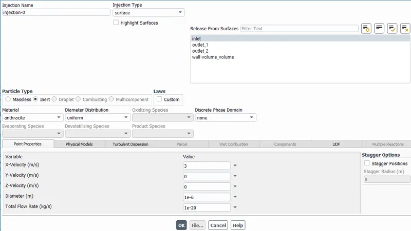
Discrete phase injections:
Particle diameters of 1,3 and 5 micro meters are injected from the inlet for different simulation runs.
Boundary Conditions
Inlet and walls: Reflect ; Outlet(Top): Escape ; Outlet(Bottom/dustbin) - Trap
Simulation Runs: Injection and air velocity as constant with 3 m/s
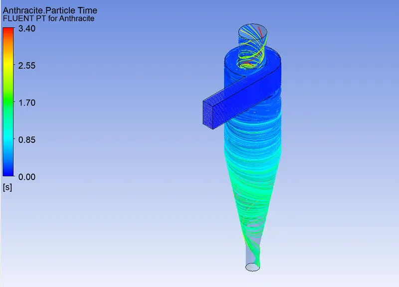
1) Particle diameter= 1e-6 m
The particle time trajectories are shown below:
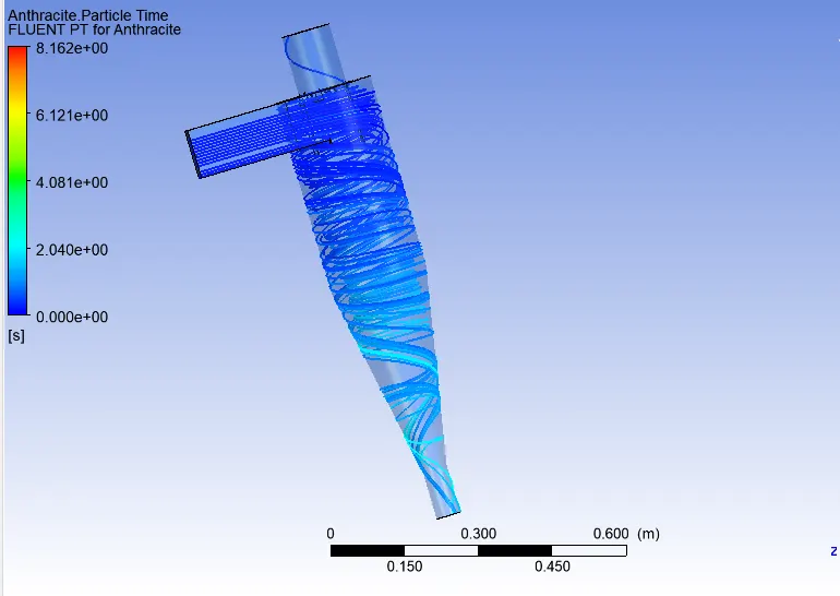
2) Particle diameter: 3e-6 m
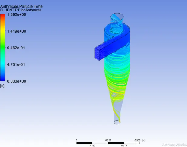
3) Particle diameter: 5e-6 m
Comparision of simulation results for injection velocity of 3m/s and varying particle sizes:
| Particle Size diameter | 1e-6 | 3e-6 | 5e-6 |
| Number of particles tracked | 136 | 136 | 136 |
| Particles Trapped | 91 | 106 | 110 |
| Particles Escaped | 31 | 19 | 12 |
| Incomplete | 14 | 11 | 14 |
| Efficiency | 0.667 | 0.776 | 0.812 |
PART 2: Varying the particle velocity from 1 to 5 m/s and same particle diameter as 5e-6 m:
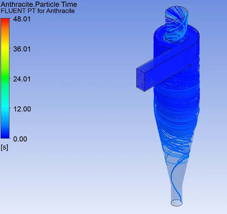
1) v= 1 m/s
The particle track plot is shown below:
The pressure plot:
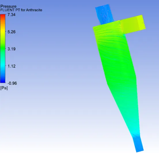
The pressure drop is given as 7.34-(-0.96) = 8.3 Pa
2) v=3 m/s
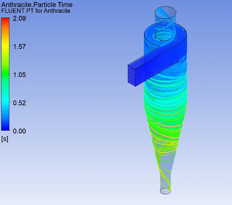
The pressure plot is shown below:
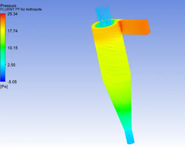
The pressure drop is 25.34-(-5.05) = 30.39 Pa.
3) V=5 m/s
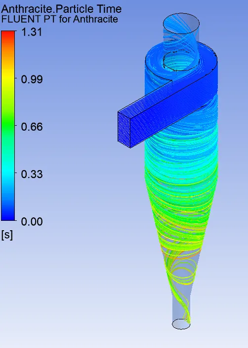
The pressure plot is shown below:
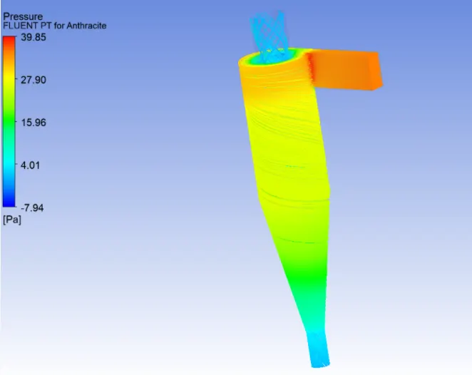
The pressure drop is 39.85-(-7.94)= 47.79 Pa
Notice that as the particle veclocity increases, the pressure drop increases.
Comparision of results for different cases considered:
| Velocity in m/s | 5 | 3 | 1 |
| Number of particles Tracked | 136 | 136 | 136 |
| Trapped | 110 | 106 | 37 |
| Escaped | 25 | 18 | 24 |
| Incomplete | 1 | 2 | 75 |
| Efficiency | 0.821 | 0.78 | 0.27 |
Note: Ideally the cyclone separator simulation requires zero incomplete particles. But due to the limitation in computation, few cases discussed above have few incomplete particles. This can be optimized with an increase by increasing the maximum no of steps in tracking parameters.
CONCLUSIONS:
- The efficiency of cyclone separators of the same size and configuration decreases as the particle size decreases.
- The efficiency of the cyclone separator increases with the increase in particle velocity.
- The pressure drop across the cyclone is of much importance in a cyclone separator. The pressure drop significantly affects the performance parameters of a cyclone. The total pressure drop in a cyclone will be due to the entry and exit losses, and friction and kinetic energy losses in the cyclone. Pressure drop increases with the inlet gas velocity, efficiency can be enhanced with the increase of inlet gas velocity.