Week 6 - CHT Analysis on a Graphics card
AIM: To perform a steady-state conjugate heat transfer analysis on a model of a graphics card.
THEORY:
The term conjugate heat transfer (CHT) describes the processes which involve variations of temperature within solids and fluids, due to thermal interaction between the solids and fluids. The exchange of thermal energy between the two physical bodies is called study of Heat Transfer, the rate of transferred heat is directly proportional to the temperature difference between the bodies.
Conjugate heat transfer corresponds with the combination of heat transfer in solids and heat transfer in fluids. In solids, conduction often dominates whereas in fluids, convection usually dominates. Efficiently combining heat transfer in fluids and solids is the key to designing effective coolers, heaters, or heat exchangers. Forced convection is the most common way to achieve high heat transfer rate. In some applications, the performances are further improved by combining convection with phase change. Heat transfer in solids and heat transfer in fluids are combined in the majority of applications. This is because fluids flow around solids or between solid walls, and because solids are usually immersed in a fluid.
Cooling systems in Graphics card:
Computer cooling is required to reduce waste heat produced by the computer components to keep them within the operating limits. Exceeding the operating limits would cause temprorary or permanent damage to the components. so it is neccessary that the component should be in the permissible limits. Components that are susceptible to temporary malfunction or permanent failure if overheated include integrated circuits such as CPUs, chipsets, graphics card, and hard disks.
Use of heatsinks cooled by airflow reduces the temperature rise produced by a given amount of heat. Attention to patterns of airflow can prevent the development of hotspots. Computer fans are widely used along with heatsink fans to reduce temperature by actively exhausting hot air. There are also more exotic cooling techniques, such as liquid cooling. All modern day processors are designed to cut out or reduce their voltage or clock speed if the internal temperature of the processor exceeds a specified limit.
Graphic Card:
A graphic card is an expansion card which generates a feed of output images to a display device like monitor. The Graphics Card is responsible for rendering an image to your monitor, it does this by converting data into a signal your monitor can understand.
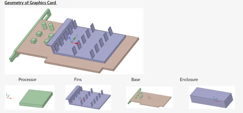
Simulation setup for Conjugate Heat transfer analysis on the graphics card:
MESHING: Using the share topology feature, all the components like proccessor, base, fins and enclosure are shared together to form conformal mesh. The formation of conformal mesh is important to observe the heat transfer effects at the surface of the solid boundary. An enclosure was formed to capture effects of convection that takes place over the graphic card.
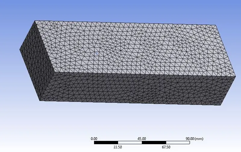
The outer enclosure is given a body sizing with element size of 5 mm as shown below. The outer enclosure is a fluid zone with air as fluid.
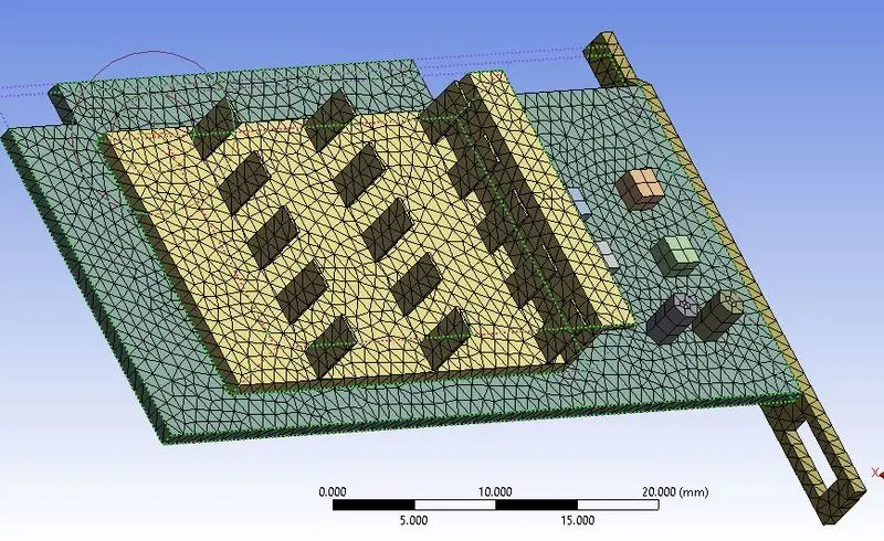
Since the inner components are small, the mesh has to be refined for the components such as processor, PCB and fins. a body sizing with an element size of 1 mm is generated as shown below. All the components are solid zone with differnt materials assigned.
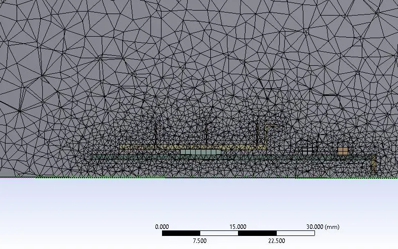
The generated econformal mesh is shown along a plane:
Case setup using ANSYS FLENT:
The pressure based solver is used with k-epsilon turbulence model of viscosity. To capture the tempreature variations in the fluid and solid domains energy equations are also used. The initial boundary conditions are:
Inlet:
Velocity of air: 1 , 3 and 5 m/s
Tempreature: 300 K
Power used by the processor: 13W
heat generated by the processor: 20000000 W/m^3
Materials used for different components of graphics card:
Fins: Copper , Proccessor: Gold, PCB base : Aluminium.
A energy source is added to the processor since it generates heat.
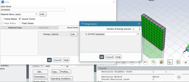
For a inlet velocity of 1m/s, the plots obtained are as follows:
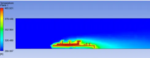
The temperature contour along a mid plane is shown:
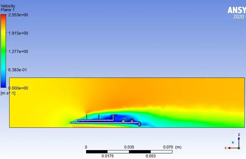
The velocity profile along the mid plane is shown:
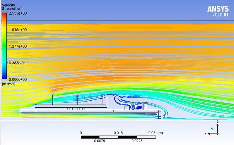
The streamlines are shown:
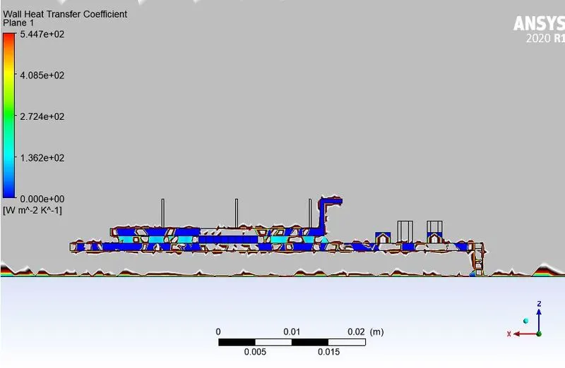
The wall heat transfer coefficient plot is shown. Notice that the maximum heat transfer coeffficient reached is 544.7 Wm^-2K^-1.
Similarly, the simulation is run with different initial velocities of air as 3 and 5 m/s and the maximum temperature range is recorded.
| S.No | Inlet velocity(m/s) | Max temperature (K) |
| 1 | 1 | 405.9 |
| 2 | 3 | 357.2 |
| 3 | 5 | 345.6 |
CONCLUSIONS:
The heat transfer rate is directly affected by velocity. As we increase the velocity the temperature on the graphic card reduces. Meshing the geomety plays a important role to capture the heat transfer in the complex geometry. Processor, which is the heat source is the potential hot spot of graphic card, because its the only component which consumes power and rejects heat. Fins play a major role in the transfer of heat from the surrounding components via convection.