Final Project: Design of an Electric Vehicle
AIM : To create a MATLAB model of electric car which uses a DC motor by choosing suitable blocks from Powertrain block set.
MODELLING AND SIMULATION:
Components of an EV -
- EVs have no need for the fuel engine and gear transmission, the two of the most crucial components for internal combustion vehicles.
- An electric powered car has three primary components - Battery, motor controller, and the electric motor.
Broadly, the EV can be represented by the following components as shown:
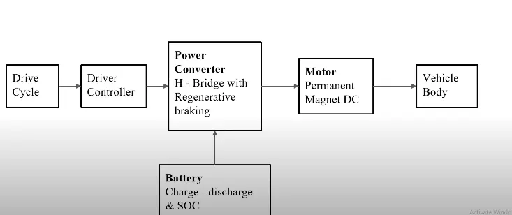
(1) Battery : The battery of an electric car can be charged through the use of ordinary grid electricity at a specialized power station. But aside from the conventional lithium-ion battery technologies, there are also other major battery technologies which can be used for electric cars.
(2) Motor Controller : The motor controller of an electric car administers its complete operation and the distribution of its power at any given moment. It acts as a floodgate between the motor and batteries. It helps monitor and regulates all key performance indications such as the vehicle’s operator, motor, battery, and accelerator pedal. It has a microprocessor which can limit or redirect current. It is used to either improve the mechanical performance of the car or suit the operator’s driving style. There are also more refined controllers which are capable of greater accuracy and thus, higher efficiency.
(3) Electric Motor : Unlike a gasoline engine with lots of moving parts, a motor only has one moving part. This makes it a very reliable source of motive power. Choosing an electric motor depends on the car’s system voltage. They can be structured to use either AC or DC current. AC motors are less expensive and lighter compared to DC motors. They are also more common and they tend to suffer from less mechanical wear and tear. However, AC technology requires a more refined or sophisticated motor controller.
Vehicle Body Subsystem :
- The vehicle is assumed to be a front axle driven (4 wheels - 2 on each axle).
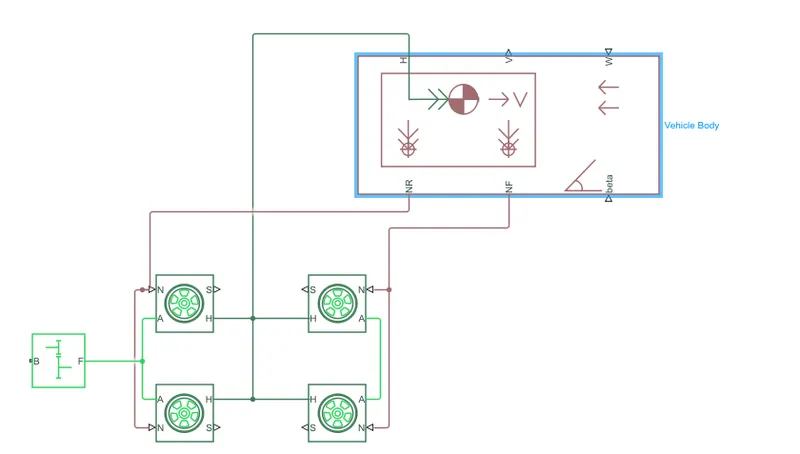
- The wheels are modelled using simple Tire (Magic formula) simulink blocks.
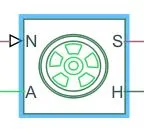
- The N port of the tire corresponds to the Normal Reaction acting on it.
The A port corresponds to the Mechanical Rotational conserving port for the wheel axle. Thus both the wheels on the same axle should form a connection through their respective A ports.
Connection H corresponds to the Mechanical Translational conserving port for the wheel hub through which the thrust developed by the tire is applied to the vehicle. Thus, all the 4 wheels form a connection through their respective H ports and this is in turn connected to the translational hub of the vehicle body.
The connection S represents the output port for slip of the tire.
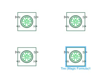
- The tires are parameterized by Peak longitudinal force and corresponding slip.
- The other block parameters such as - rated vertical load, peak longitudinal force at rated load and slip at peak force at rated load - are kept with their default values.
- The tire radius is given as 0.3 m.
- The tire inertia is kept as 1 kg-m^2. The rolling resistance is given with a constant coefficient of 0.015.
This wheel assembly is now connected to a Velocity Body simscape block as shown below.
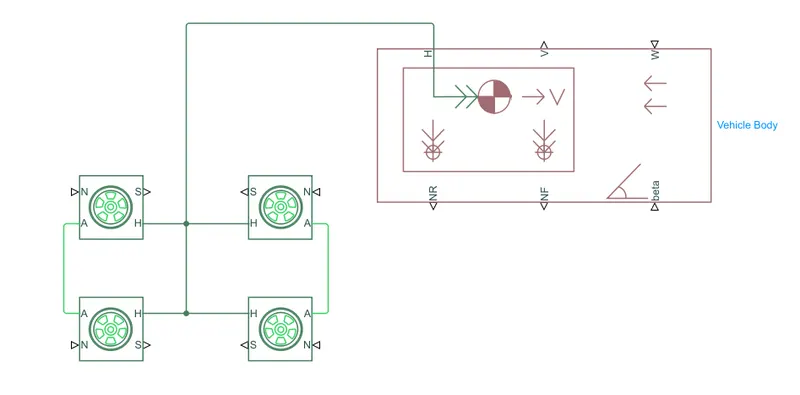
- The vehicle block basically represents a two-axle vehicle body in longitudinal motion. The block accounts for body mass, aerodynamic drag, road incline, weight distribution between axles due to acceleration and road profile.
- Inside the vehicle body, the connection H is the mechanical translational conserving port hub.
NF & NR correspond to the output ports for nomral reaction forces on front axle and rear axle wheels respectively.
Connection V represents the actual output translational velocity of the vehicle.
beta is the road inclination angle & W corresponds to the headwind speed. - Assuming the rear wheel drive, the real wheel axis is connected to the gear system block as shown below.
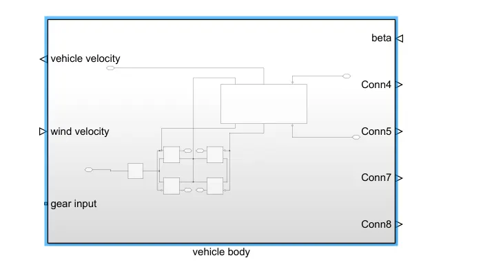
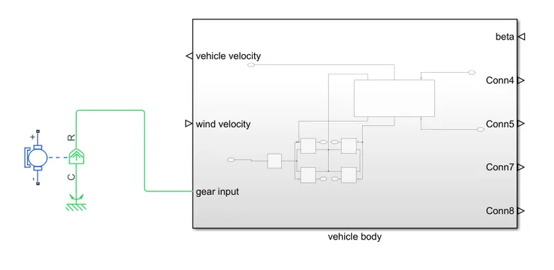
The entire vehicle subsystem is converted into a single subsystem block as shown. The input for this subsystem is taken as the Rotational speed of the motor. This input is fed to the front axle through a Simple Gear representing the Final Drive Ratio of 6.
DC Motor :
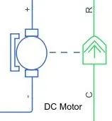
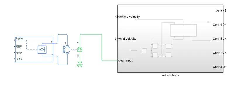
- Simulink provides an inbuilt bodel block for DC motor which converts electrical input into mechanical rotational output. Here, the blue colour corresponds to the electrical side of the motor and the green colour corresponds to the mechanical side.
- The + and - terminals of the motor are connected to the motor controller. If these terminals are directly connected to a battery, the required DC motor will run on the rated capacity of the battery. This will eventually result into no control over the DC motor and the vehicle will run at top speed throughout the simulation.
The DC motor parameters are considered as shown below:
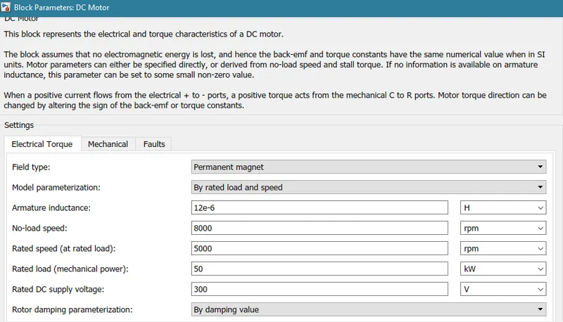
The terminals of the motor is now connected to a H bridge as shown below.
- The H bridge block can be driven by the Controlled PWM Voltage block in PWM or Averaged mode.
- In PWM mode, the motor is powered if the PWM port voltage is above the enabled threshold voltage.
- In Averaged mode, the PWM port voltage divided by the PWM signal amplitude parameter defines the ratio of the on-time to the PWM period.
- Connection REF is for the reference input. This combined with the PWM connected will form the pulse input for the H-Bridge. Here, the REF input is connected to the Electrical Reference (ground).
- Connection REV corresponds to the reverse motion of the motor which essentially means, the backward motion of the vehicle. Here, the backward motion of the vehicle is not accounted for and so, the port is connected to the electrical reference.
- Connection BRK is for the braking of the vehicle.
- Since, the PWM mode results in a huge amount of simulation time, Averaged mode is selected for this simulation and Load current characteristics are considered to be smoothed here. Regenerative braking is also enabled.
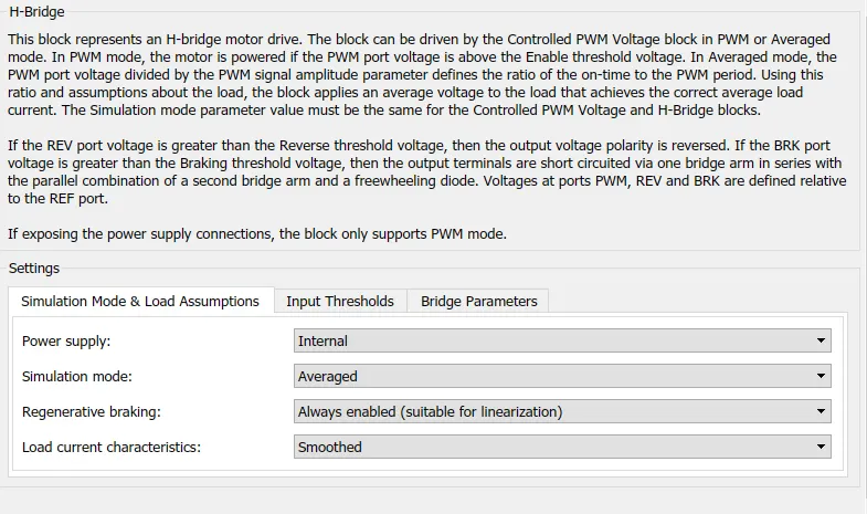
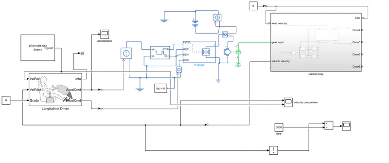
Controlled PWM Voltage block is used for providing the proper pulse inputs to the H-Brdige circuit. The 2 reference inputs correspond to the throttle inputs given by the driver. The block generates corresponding pulse width as per the accelerations and brakes apllied by the driver himself. This block is connected to the H-bridge as shown. 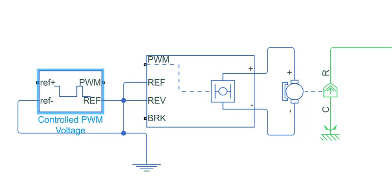
Longitudinal Driver :
- Longitudinal Driver is an inbuilt block provided by the powertrain blockset.
- The VelRef port is the reference velocity port where the input drive cycle data is fed. The VelFdbk port corresponds to the feedback velocity. The actual velocity output given by the vehicle body is connected here. By comparing the actual (feedback) velocity with the reference velocity, the driver block generates acceleration and braking signals in order to minimise the error between the two concerned velocities.
- Grade corresponds to the grade angle. Grade is considered 0 in this case. AccelCmd & DecelCmd correspond to the acceleration and deceleration commands generated respectively and are connected to the corresponding ports of the Controlled PWM Voltage block.
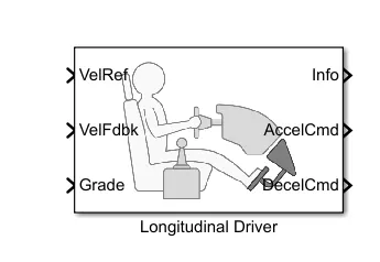
The longitudinal driver block is connected to the controller block as shown.
Battery Pack:
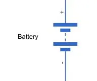
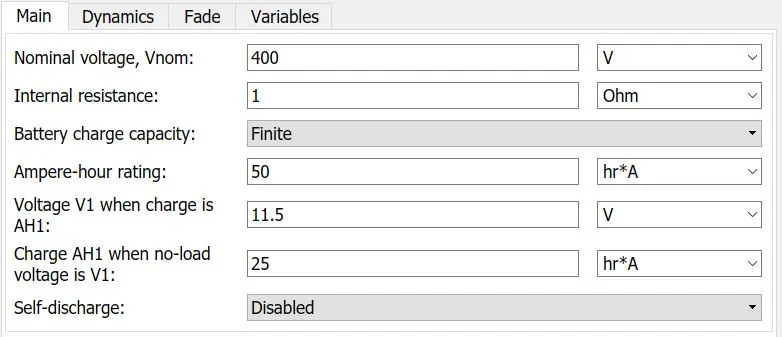
- To model the Battery pak, a simple Battery block is used. A finite battery charge capacity with a nominal voltage of 400 v is modelled.
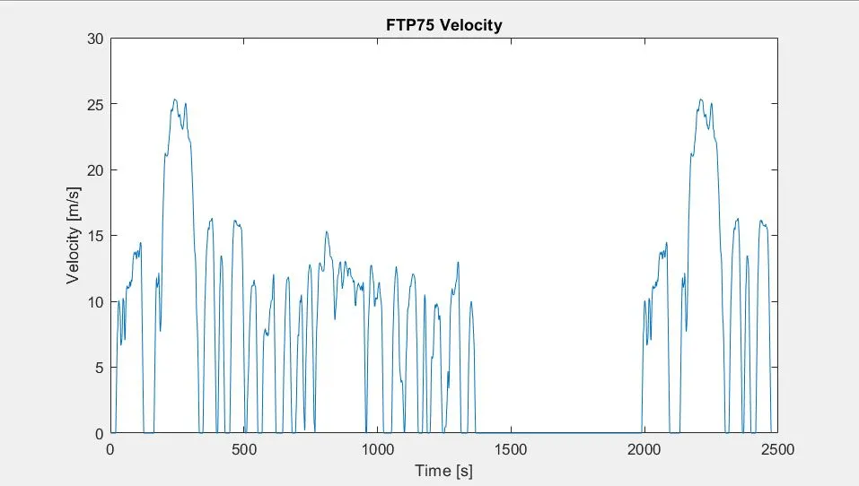
A standard FTP75 drive cycle is used as a reference speed for the simulation. The plot of the drive cycle is shown:
Results and Plots:
Reference speed vs actual speed achieved:
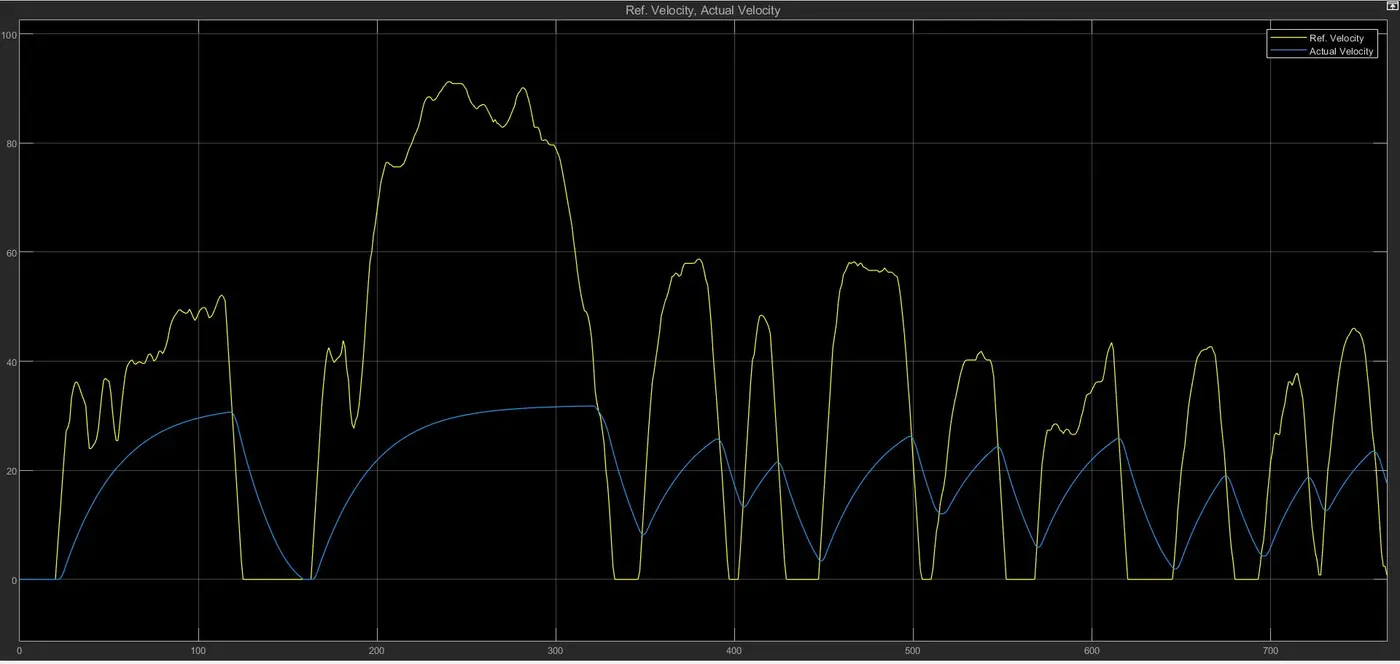
The reference and the actual speed do not match exactly since the chosen battery capacity and motors are not able to propel the speed upto the required extent. In certain regions, despite the drive cycle showing small decelerations, the vehicle actually is accelerating with decreasing magnitudes. If a battery of higher capacity is chosen, the actual velocity will tend to match with the reference velocity.
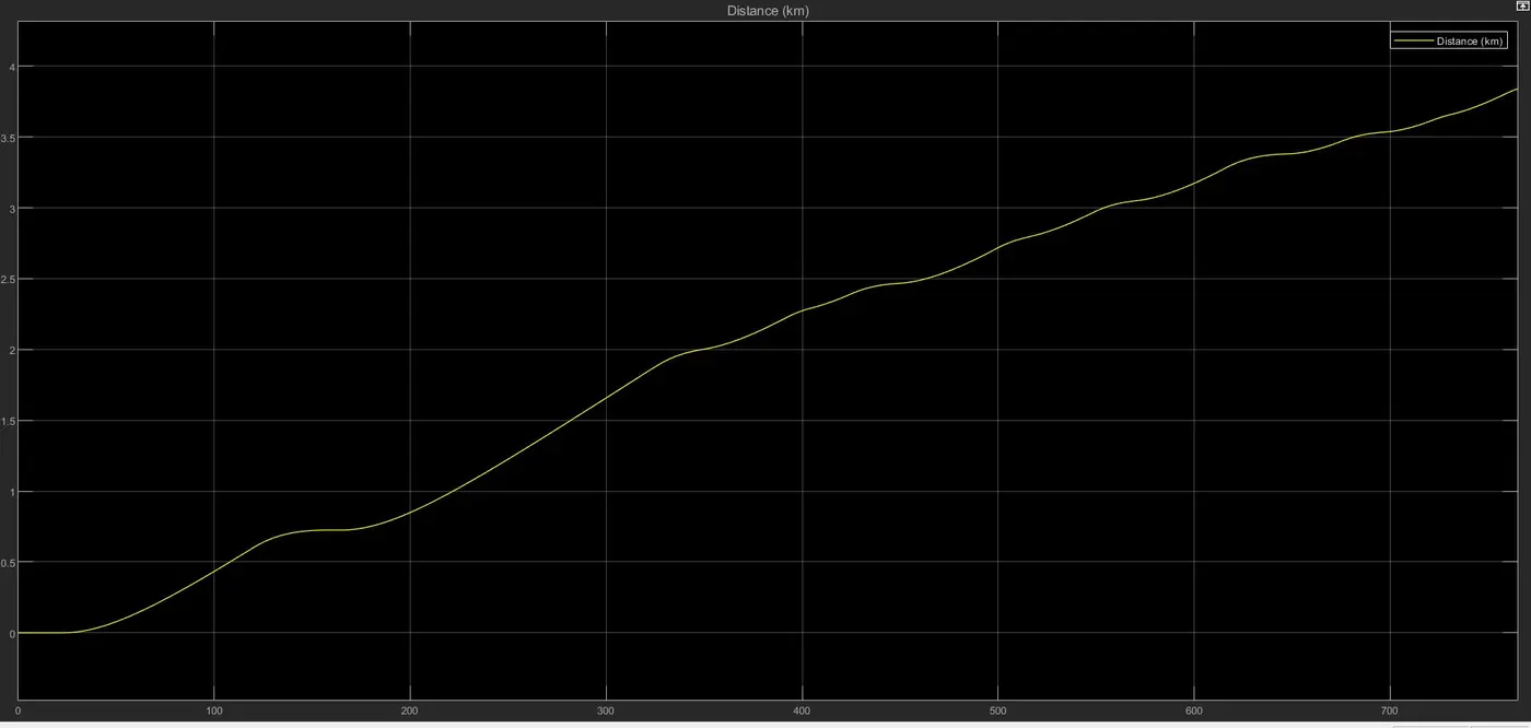
Distance covered:
The battery state of charge:
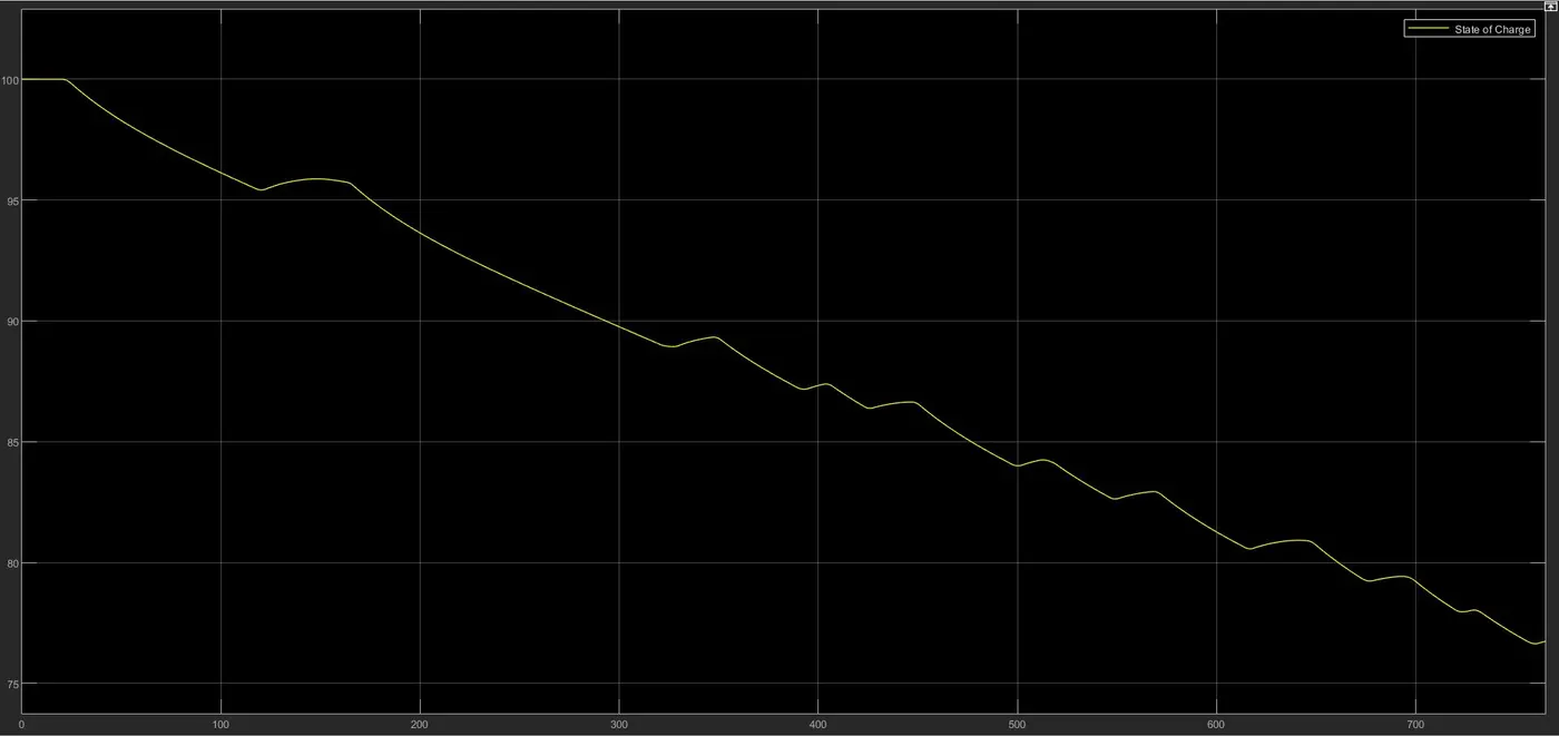
Notice that the State-of-Charge of the battery at the end of simulation run is nearly about 77 %. Since the regenerative braking for the simulation is enabled, the battery SOC increases slightly whenever the vehicle undergoes heavy deceleration.