Week 9 - Parametric study on Gate valve.
AIM:- To perform Parametric on the Gate Valve by setting the opening height.
Objective:-
- To perform the Parametric study for 10 % to 80% valve opening.
- To calculate and compare the Mass Flow Rate for different cases.
- To calculate the flow coefficient and flow factor for each opening.
Theory:-
A gate valve is generally used to completely shut off fluid flow or, in the fully open position, provide full flow in a pipeline. Thus it is used either in fully closed or fully open positions. A gate valve consists of a valve body, seat and disc, a spindle, gland, and a wheel for operating the valve.
Gate valves are used when a straight-line flow of fluid and minimum flow restriction are needed. Gate valves use a sliding plate within the valve body to stop, limit, or permit the full flow of fluids through the valve. The gate is usually wedge-shaped. When the valve is wide open, the gate is fully drawn into the valve bonnet. This leaves the flow passage through the valve fully open with no flow restrictions. Therefore, there is little or no pressure drop or flow restriction through the valve.
Gate valves are not suitable for throttling volume. The control of flow is difficult because of the valve's design and the flow of fluid slapping against a partially open gate can cause extensive damage to the valve. It should be noted that the stem motion in a gate valve is typically linear, which creates a lot of friction between the valve stem and packing. This friction can cause packing wear and tear as well as leakage.
Procedure:-
In this project, we analyze the result for the different opening of gate valve, as the geometry keeps on changing for different valve opening conditions it is tedious to the setup for all the cases. In order to this simulation easy and time-consuming, we are going to use parametric analysis.
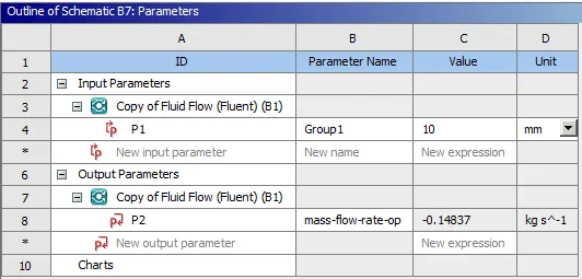
Here we have varying parameters is the Opening Height of Gate Valve, we set its valve Height as Input Parameter and Mass Flow Rate as the Output Parameter.
ANSYS Workbench (Fluent) is used for the solution.
Geometry
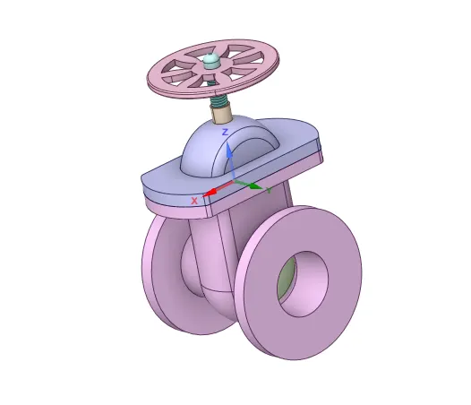
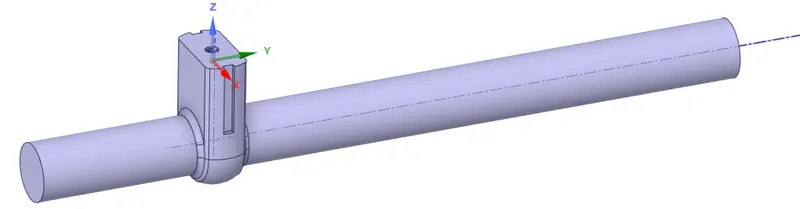
- Import the Gate Valve model in SpaceClaim and visualize all the components in the gate valve assembly for cleanup.
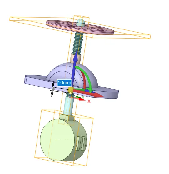
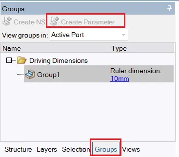
- As we want to do the Parametric analysis for the height of the valve, we move the gate disc upwards direction by 10mm using the Move tool. And set this Height Parameter by creating it in groups using Create Parameter option. A ruler dimension of 10mm is then got created which is parameterized which the n is used under different case studies by varying the ruler dimension value.
- For the creation of proper flow volume, the length of the base is elongated, 200mm for the inlet, and 800mm for the outlet by using the pull tool. This is done to have a fully developed region for the analysis at the outlet that will be free from flow characteristics fluctuations.
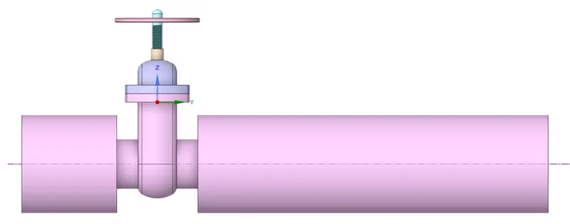
- Fluid volume(wet volume) is then extracted from the domain.
Meshing
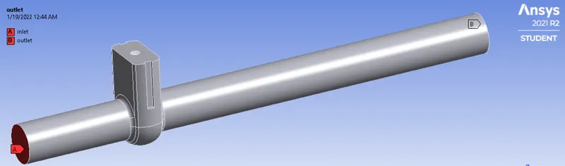
- Firstly we name the inlet and outlet by selecting the face.
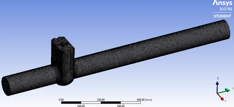
- Meshing is done with an element size of 5 mm.
Cell count - 414269
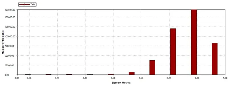
Mesh Quality
Setup
|
Solver Type |
Pressure-Based |
|
Velocity Formulation |
Absolute |
|
Time |
Steady |
|
Gravity |
negative y-direction (9.81 m/s) |
|
Viscous Model |
K-epsilon > Realizable > Scalable wall Function |
|
Material |
Fluid type- Water(h2o-liquid) |
|
Boundary Condition |
Inlet - Pressure inlet (Gauge total pressure = 10 Pa) Outlet - Pressure outlet (Gauge pressure = 0 Pa) Walls - Stationary wall with no-slip condition |
|
Solution Method |
pressure-velocity coupling- Coupled |
|
Initialization |
Standard Initialization |
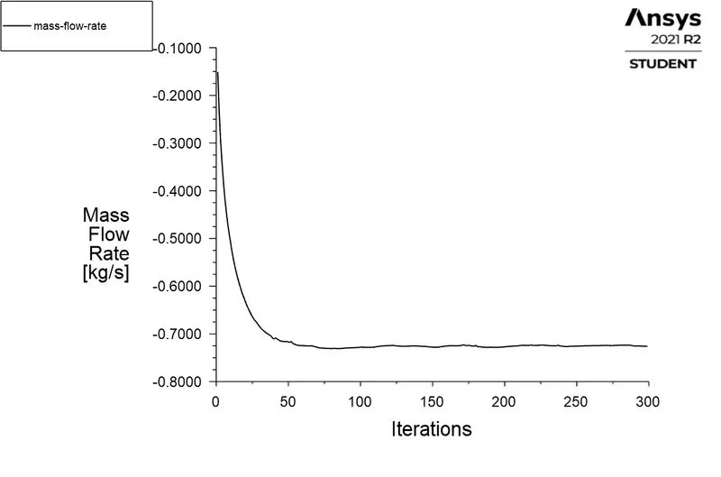
- Flux report for Mass Flow Rate at the outlet is created and selected "create an output parameter" to get mass flow rate output for all the cases in the parametric study.
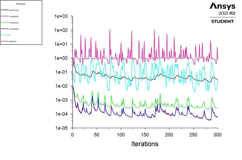
- The Simulation is then run 300 iterations after the setup.
Parametric study
- After the simulation is completed, we will perform the Parametric study.
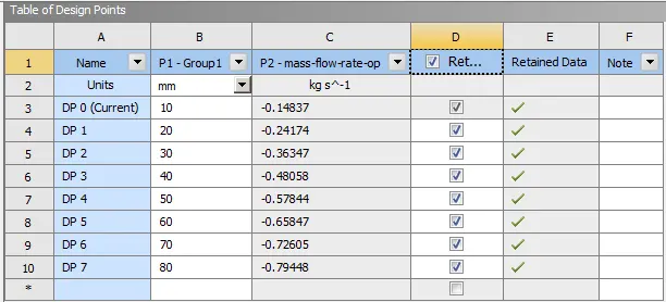
- In Ansys workbench go to the Parameters tab, here Design points are created for different opening valve heights.
- To view the calculated results for the desired design point, check the retained option for all the design points.
- Then update the design point individually to get the result for all the cases.
- Finally, to see the results for different cases select the design point and set it as current, results were post-processed in the Fluent project.
Post Processing:-
Post Processing
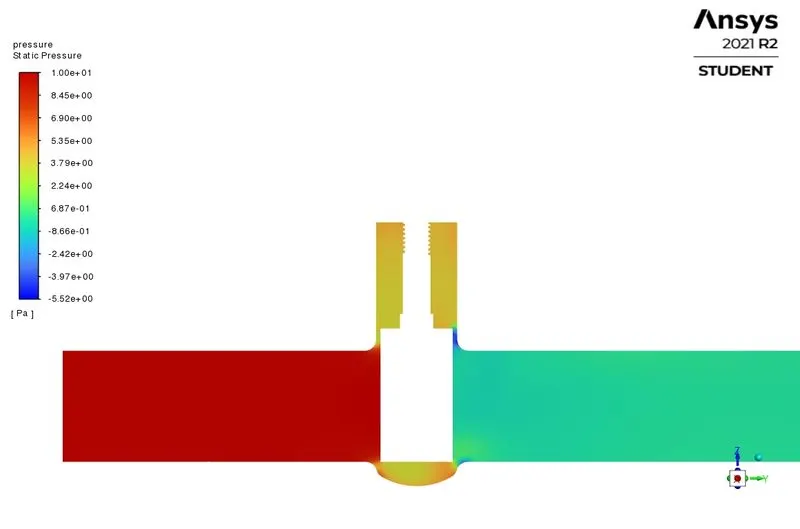
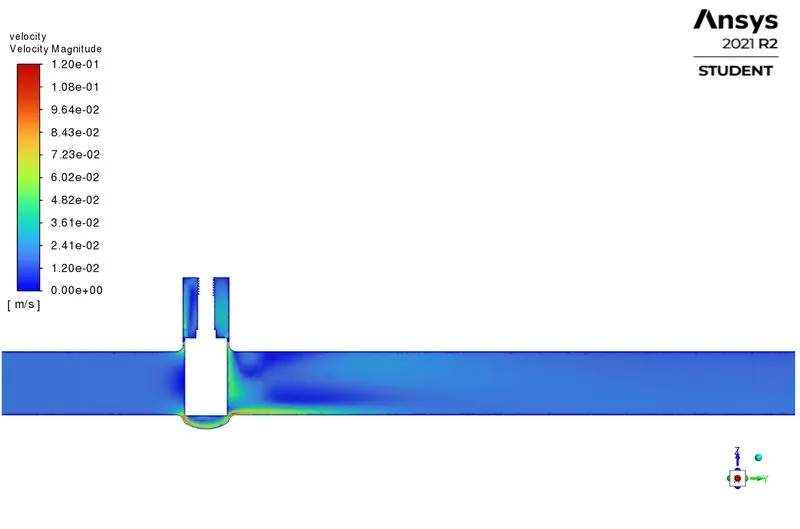
CASE 1 - 10% Opening of Gate Valve
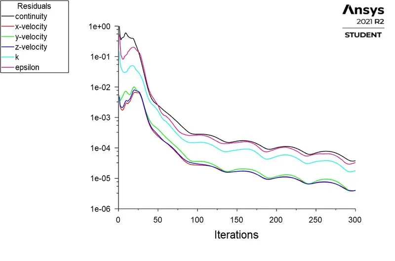
Residuals
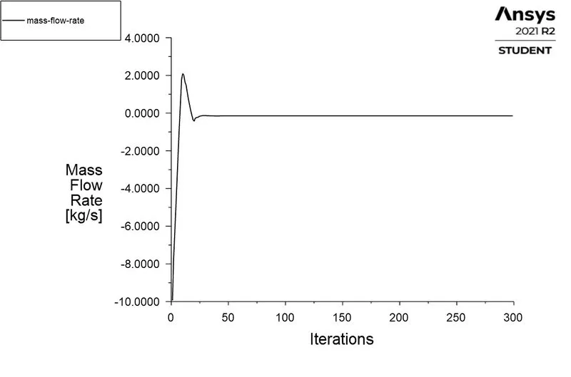
Mass Flow Rate
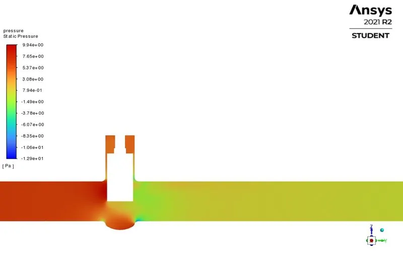
Pressure Contour
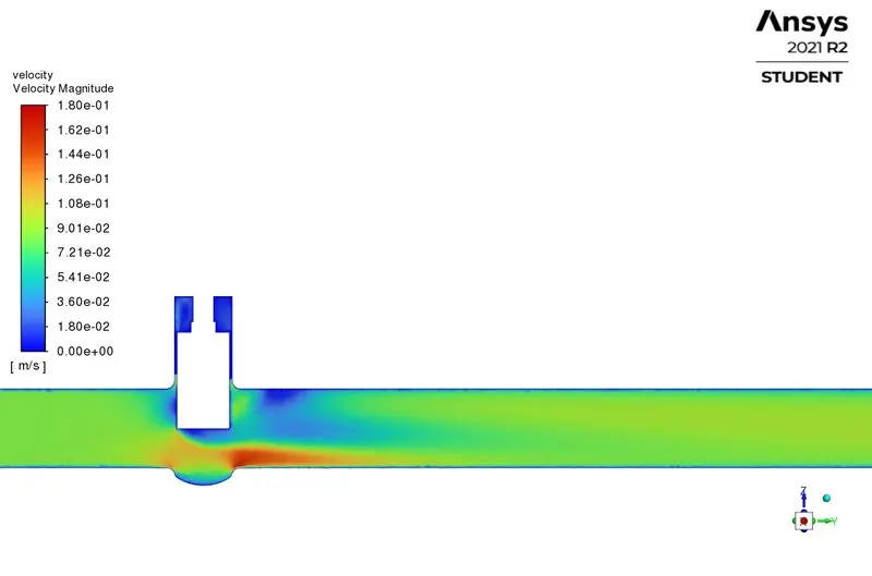
Velocity Contour
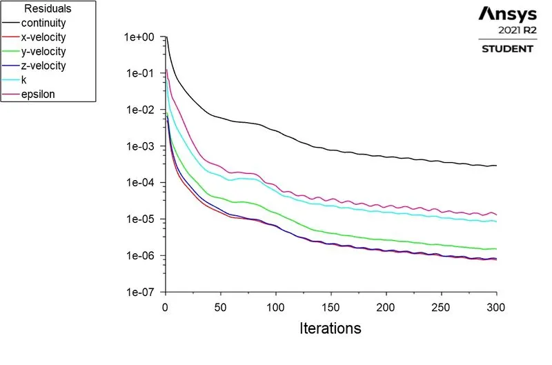
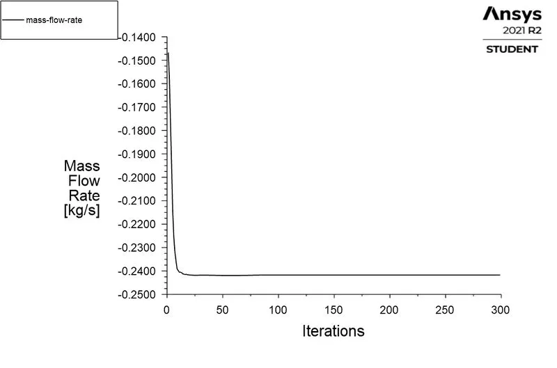
CASE 2 - 20% Opening of Gate Valve
Residuals
Mass Flow Rate
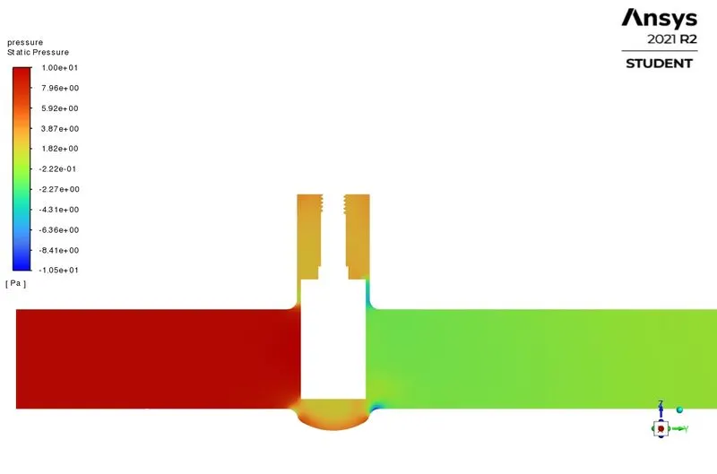
Pressure Contour
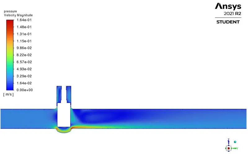
Velocity Contour
CASE 3 - 30% Opening of Gate Valve
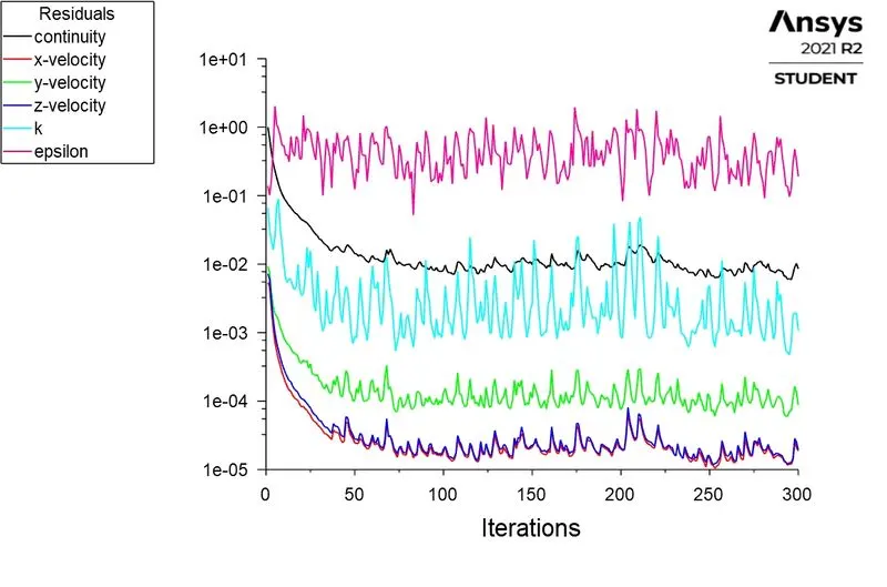
Residuals
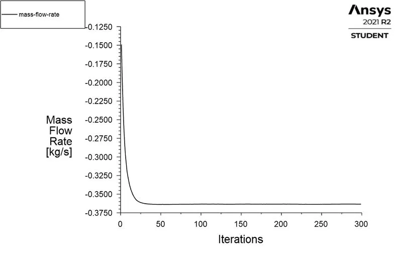
Mass Flow Rate
Pressure Contour
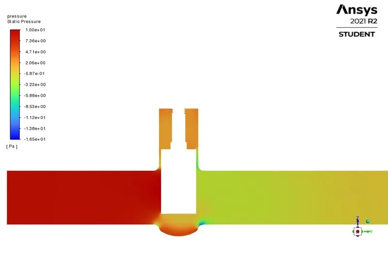
Velocity Contour
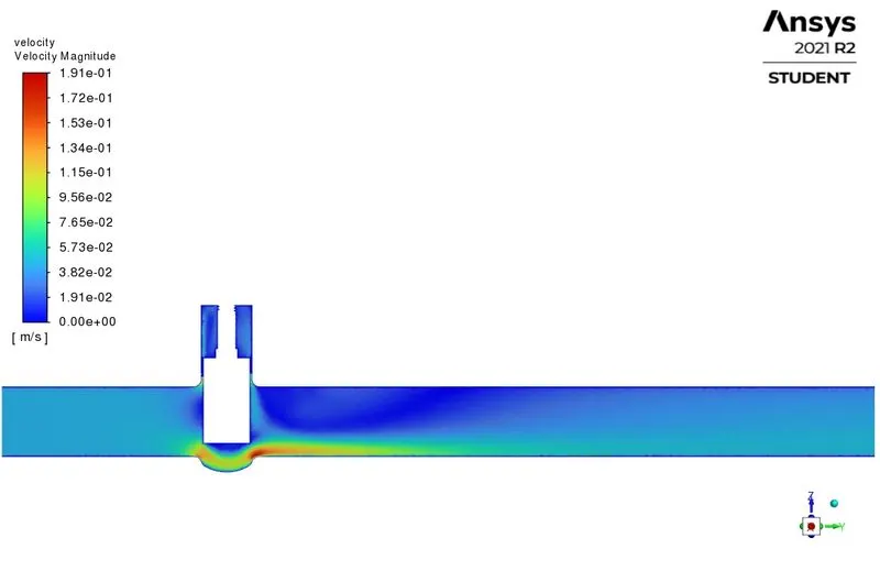
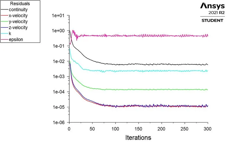
CASE 4 - 40% Opening of Gate Valve
Residuals
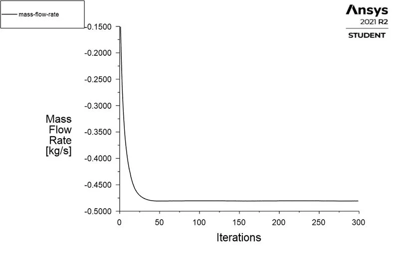
Mass Flow Rate
Pressure Contour
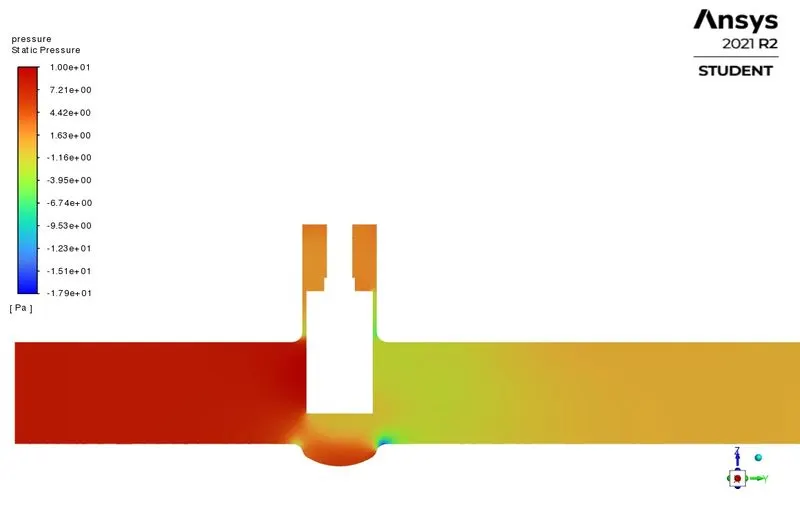
Velocity Contour
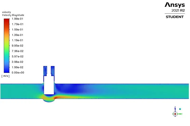
CASE 5 - 50% Opening of Gate Valve
Residuals
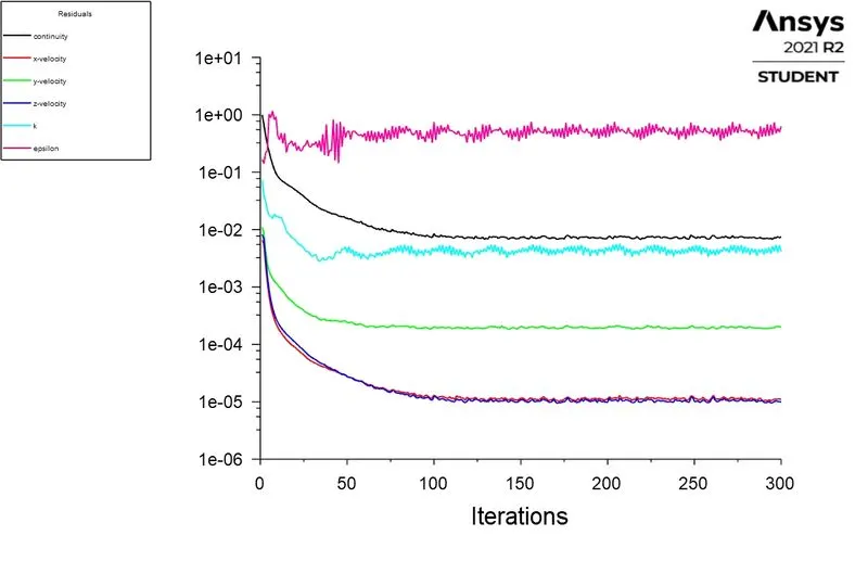
Mass Flow Rate
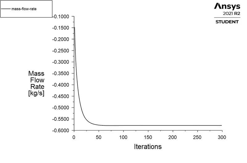
Pressure Contour
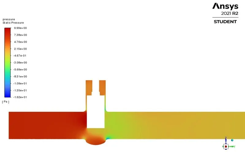
Velocity Contour
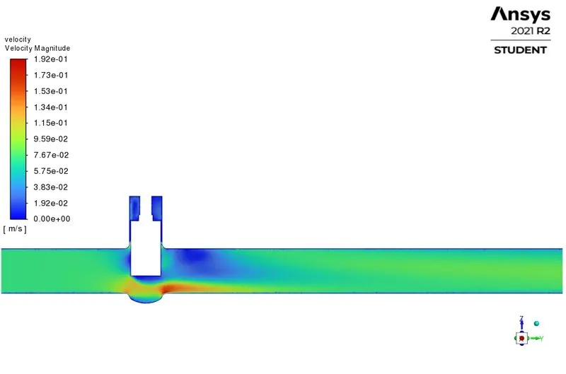
CASE 6 - 60% Opening of Gate Valve
Residuals
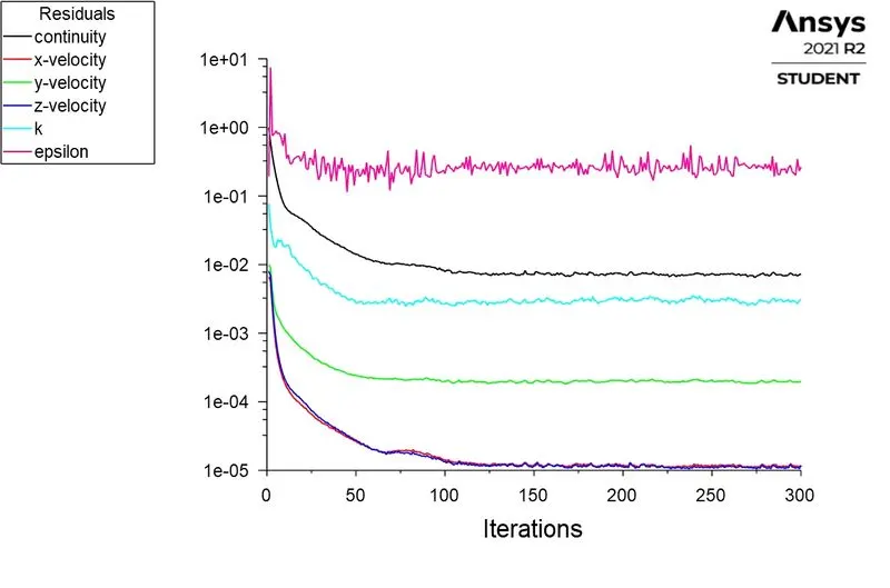
Mass Flow Rate
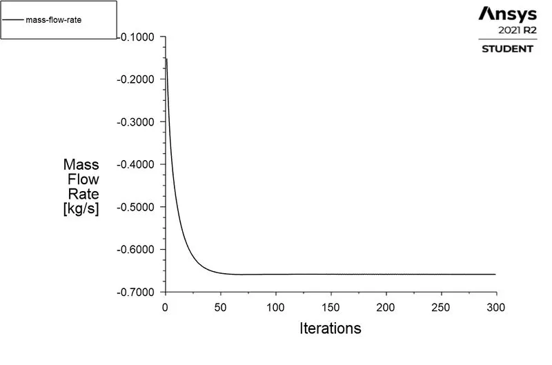
Pressure Contour
Velocity Contour
CASE 7 - 70% Opening of Gate Valve
Residuals
Mass Flow Rate
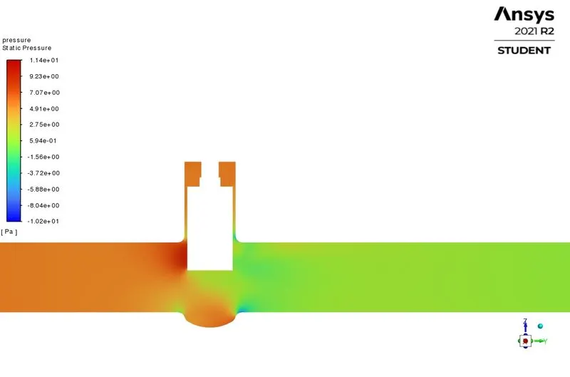
Pressure Contour
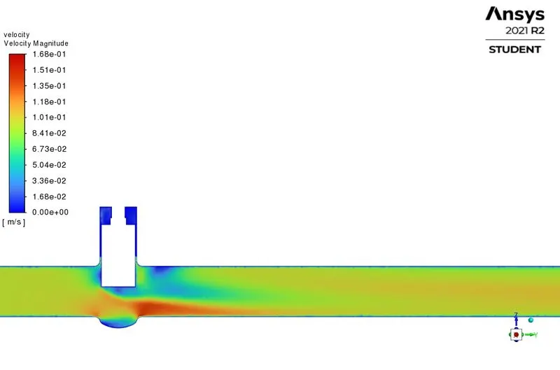
Velocity Contour
CASE 8 - 80% Opening of Gate Valve
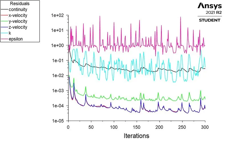
Residuals
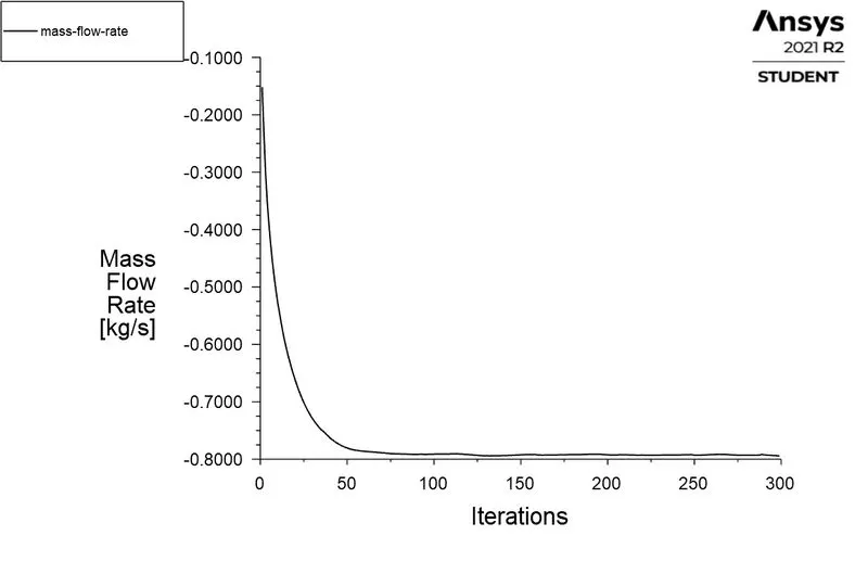
Mass Flow Rate
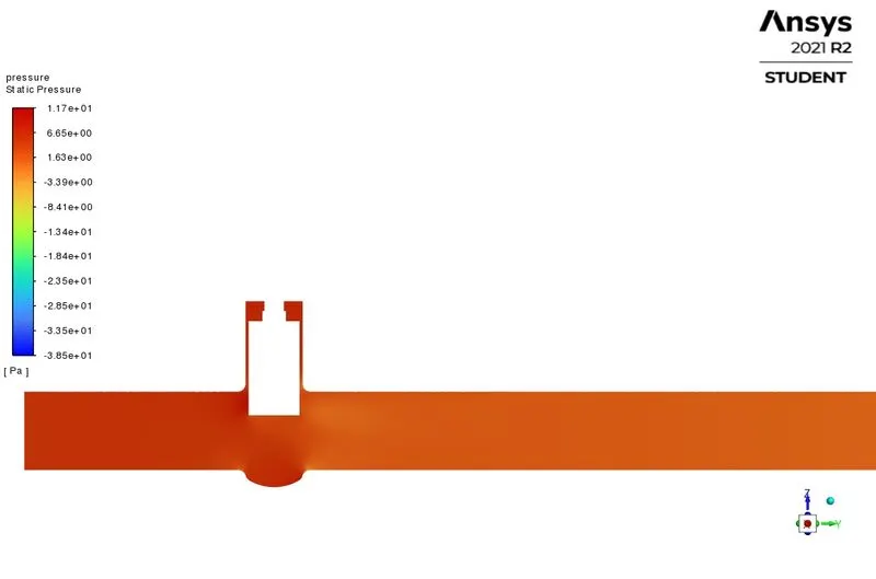
Pressure Contour
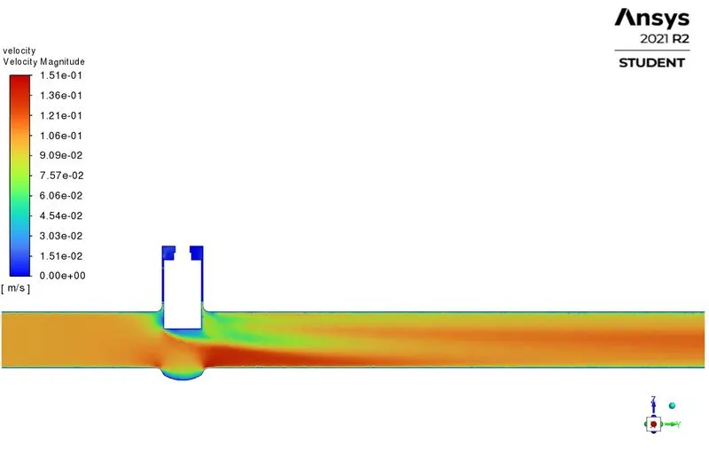
 Velocity Contour
Observations/Calculations:-
Flow Coefficient(Cv) and Flow factor(Kv) can be calculated using output parameters, Mass Flow Rate, and Pressure Drop.
Flow coefficient (Cv)
The flow coefficient of an instrument is a relative measure of the efficiency to allow the fluid flow. It is also called as Flow Capacity Rating of the valve.
It describes the relationship between the pressure drop across an orifice valve and the corresponding flow rate, and is given as,
`Cv=Q(sqrt((SG)/(nabla p)))`
where,
Cv = Flow coefficient (Us gallons/min)
Q = Flow rate (Us gallons/min)
SG = Specific gravity of the fluid.
`nabla p` = Pressure drop (Psi)
The flow coefficient(Cv) is the volume(Us gallons) of water at `60^o F` that will flow per minute through a valve with a pressure drop of 1Psi across the valve.
The use of flow coefficient offers a standard method of comparing valve capacities and sizing valves for specific applications that are widely accepted by the industry.
Flow Factor (Kv)
The metric equivalent is called as flow factor (Kv).
Flow factor can be given as,
`Kv=Q(sqrt((SG)/(nabla p)))`
where, Kv = Flow factor (`m^3/(hr)`)
Q = Flow rate (`m^3/(hr)`)
SG = Specific gravity of the fluid.
`nabla p` = Pressure drop (bar)
Flow factor (Kv) can be calculated from flow coefficient (Cv) using the equation,
`Kv=0.865 times Cv`
The Flow Factor(Kv) indicates the water flow in (`m^3/(hr)`), at a pressure drop across the valve of `1(Kgf)/(cm^2)` when the valve is completely open.
| Gate Valve (mm) | Mass Flow Rate (Kg/s) |
Mass Flow Rate (gal/min) | Pressure Drop (Pa) |
Pressure Drop (psi) |
Flow coefficient (Cv) |
Flow Factor (Kv) |
| 10 | 0.14837 | 2.3516645 | 9.8208076 | 0.00142439 | 62.31044611 | 53.89853589 |
| 20 | 0.24173 | 3.8314205 | 9.5242652 | 0.00138138 | 103.0868282 | 89.17010643 |
| 30 | 0.36347 | 5.7609995 | 8.9246627 | 0.001294415 | 160.1256961 | 138.5087271 |
| 40 | 0.48057 | 7.6170345 | 8.1195379 | 0.001177642 | 221.9623758 | 191.9974551 |
| 50 | 0.57843 | 9.1681155 | 7.276059 | 0.001055305 | 282.2221322 | 244.1221444 |
| 60 | 0.65847 | 10.4367495 | 6.4698353 | 0.000938372 | 340.7044029 | 294.7093085 |
| 70 | 0.72604 | 11.507734 | 5.7139539 | 0.00082874 | 399.7427054 | 345.7774402 |
| 80 | 0.79448 | 12.592508 | 4.8707459 | 0.000706443 | 473.7765896 | 409.81675 |
- The above observation table shows the relationship between the Flow Field variables for all the cases.
- It can be clearly seen that the Mass flow rate at the outlet starts increasing as the valve is uplifted, which is sensible that if there is less restriction to flow, the Mass flow rate at the outlet will increase and vice versa.
- There is a decrease in pressure drop in the fluid flow as the barrier is uplifted.
- The Flow Coefficient(Cv) and Flow Factor(Kv) increase with respect to the lift of the gate valve. This is because more volume of water is allowed to pass per unit time through the vena contracta(restricted section).
Graph
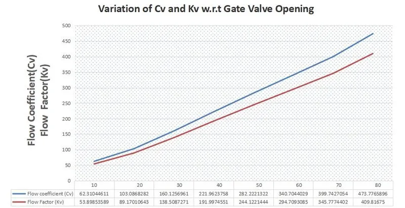
The above Graph shows the variation Flow Coefficient(Cv) and Flow Factor(Kv) with respect to the Gate Valve opening, X-axis shows the Gate Valve opening(mm) and Y-axis shows the Flow Coefficient(Cv) and Flow Factor(Kv).
It can be clearly observed that the Flow coefficient and Flow Factor increase with the increase in Mass flow rate.
Conclusion:-
- The obtained results in this study are validated, it is observed that they obey the actual physics and flow phenomenon.
- It can be clearly seen in the above observation table that the Mass flow rate at the outlet increases as the barrier to flow is uplifted. Ans the Flow coefficient and Flow Factor also increases.
- We can conclude that Mass Flow Rate is maximum when the valve is fully open
- Thus, a Parametric study helps us to analyze the different parameters in an easy and efficient way.