Week 10 - Simulating Combustion of Natural Gas.
AIM:- To perform the study on combustor model using Ansys Fluent
Objective:-
- To perform the combustion simulation of a non-premixed model
- To study the effect of the chemical reaction on adding the water content in the fuel
Theory:-
Combustion or burning is a chemical process where any fuel has a reaction with air (oxidant) to produce heat energy. As a product, it is producing gases in the form of smoke. Complete combustion is stoichiometric concerning the fuel, where there is no remaining fuel, and ideally, no residual oxidant. Thermodynamically, the chemical equilibrium of combustion in air is overwhelmingly on the side of the products. However, complete combustion is almost impossible to achieve, since the chemical equilibrium is not necessarily reached, or may contain unburnt products such as carbon monoxide, hydrogen, and even carbon(soot or ash). Any combustion at high temperatures in atmospheric air, which is 78% nitrogen, will also create a small number of nitrogen oxides, commonly referred to as NOx.Thus, the produced smoke is usually toxic and contains unburned or partially oxidized products.
Hydrocarbon + Oxygen → Carbon Dioxide + Water + Heat Energy
Examples of Combustion-
- Burning of Wood or Coal to produce heat energy.
- Burning of Petrol or Diesel to run the vehicles, factories.
- Combustion of Natural Gas or LPG for cooking purposes.
- A nuclear reaction in nuclear power plants to generate electricity.
Major Pollutants from Combustion:-
Nitrogen Oxide (NOx)
- Nitrogen oxide comprises majorly NO (nitric oxide). But Two other oxide of nitrogen such as Nitrogen Peroxide and N2O (Nitrous oxide) can be formed
- Nitric oxide (NO) reacts with oxygen or excess air to form NO2
- NOx is a Highly regulated pollutant That can result in photochemical smog, This pollutant contributes to ozone depletion and acid rain
- There are four different mechanisms to form NOx: Thermal, Prompt, Fuel, and N2O route
Soot Particles
- Soot particles are generally formed due to incomplete combustion or pyrolysis in a rich mixture of a hydrocarbon fuel with strong temperature gradients in the combustion chamber
- Aggregates of Spherical carbon particles are observed within flames. Soot observed in domestic fires or chimneys contains few aggregates but large amounts of particulate fragments of coke or char are found.
- The formation of soot particles is a complex phenomenon: nucleation, surface growth, coalescence, aggregation
Types of NOx formation mechanism:-
Thermal NOx
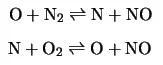
- The formation of NOx is determined through the Oxidation of atmospheric nitrogen at high temperatures by the Zeldovich mechanism
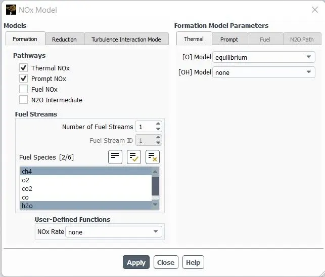
- The user chooses [O] model as equilibrium or partial equilibrium (recommended)
- Thermal NO formation proposed by Zeldovich Mechanism is given as
Prompt NOx
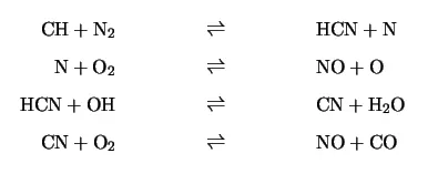
- It is produced in a lower temperature and fuel-rich condition at a short residence time.
- Formed predominantly through the intermediate HCN
- The formation involves a complex reaction with a number of intermediate species.
Fuel NOx
- Fuel nitrogen to NOx is dependent on the local combustion characteristics and the initial concentration of nitrogen-bound compounds.
- Fuel-bound compounds that contain nitrogen are released into the gas phase when the fuel droplets or particles are heated during the devolatilization stage. From the thermal decomposition of these compounds, (aniline, pyridine, pyrroles, etc.) in the reaction zone, radicals such as HCN, NH, N, CN, and NH can be formed and converted to NOx.
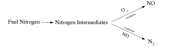
- The above free radicals (i.e., secondary intermediate nitrogen compounds) are subject to a double competitive reaction path. Below, is a simplified model of the same:
NOx from intermediate N20
- In the intermediate mechanism, NOx is Produced from molecular nitrogen (N) via nitrous oxide (NO).
- Nitrogen enters combustion systems mainly as a component of the combustion and dilution air, and under favorable conditions of elevated pressure and oxygen-rich conditions, this intermediate mechanism can contribute as much as 90% of the NOx formed during combustion.
- The simplest form of the mechanism takes into account two reversible elementary reactions
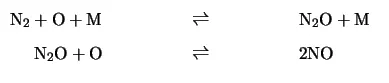
- Here M is the third body.
Study:- In this project, we will be simulating the combustion of air and fuel(methane) mixture inside a cylindrical combustor. Here, the source term is modeled using the eddy-dissipation model where the beginning of ignition(ignition delay) is calculated using a turbulent time scale. This means that the ignition will start depending on when the turbulent quantities reach a limiting value. This approximation helps us to visualize the steady-state temperature distribution in the combustion chamber at a faster rate. This type of mixing-based model is called a Turbulence Chemistry interaction model.
Procedure:-
In this project, we will analyze the result while adding the water content in the fuel from 5% to 30% by mole.
ANSYS Workbench (Fluent) is used for the solution.
Geometry
- Import the model in SpaceClaim for cleanup.
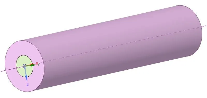
- As simulation for this whole body is time-consuming and expensive, we assume the combustion properties are axisymmetric, therefore we Split the domain with different planes in order to use the extracted mid-2D geometry for the analysis.
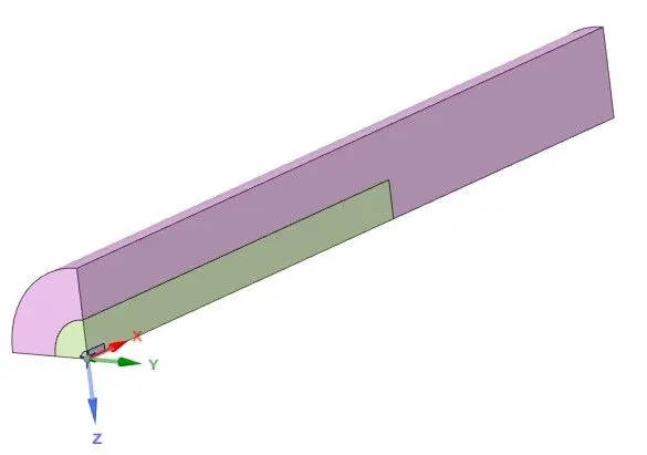
Also in order to mesh interface properly for proper sharing of information, share topology is made.

Meshing
- Firstly we name the inlet fuels, outlet, and symmetric as per requirement.
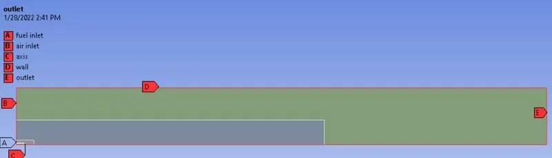
- Meshing is done with an element size of 1 mm and capture curvature and proximity are kept on
- Cell count - 68304
Setup
|
Solver Type |
Pressure-Based |
|
Velocity Formulation |
Absolute |
|
2D Space |
Axisymmetric |
|
Time |
Steady State |
|
Viscous Model |
K-epsilon > Standard > Scalable wall Function Energy - On |
|
Models |
Species > Species Transport - On |
|
Material |
Fluid Type - Air Solid Type - Aluminum Mixture - Methane-air-2step |
|
Boundary Condition |
Air Inlet - Fuel Inlet - Outlet - Pressure outlet (Gauge pressure = 0 Pa) Walls - Stationary wall with no-slip condition Axis - Axisymmetric (x-axis) |
|
Solution Method |
pressure-velocity coupling- COUPLED |
|
Initialization |
Standard Initialization |
Species Models-
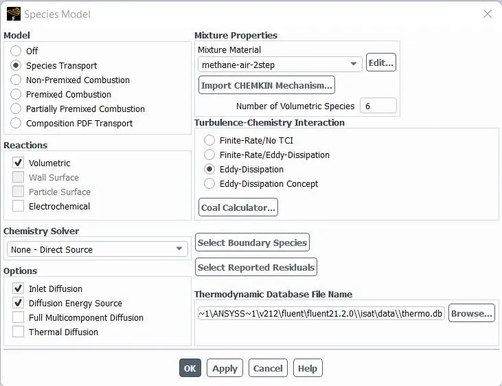
NOx Model-
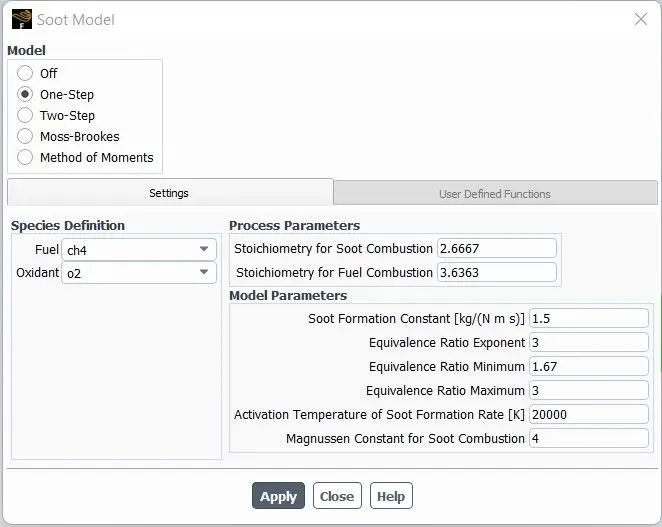
Soot Model-
Cases-
| Mole Fraction (Cases) | `CH_4` | `H_2O` |
| Case 1 | 1 | 0 |
| Case 2 | 0.95 | 0.05 |
| Case 3 | 0.9 | 0.1 |
| Case 4 | 0.8 | 0.2 |
| Case 5 | 0.7 | 0.3 |
Results:-
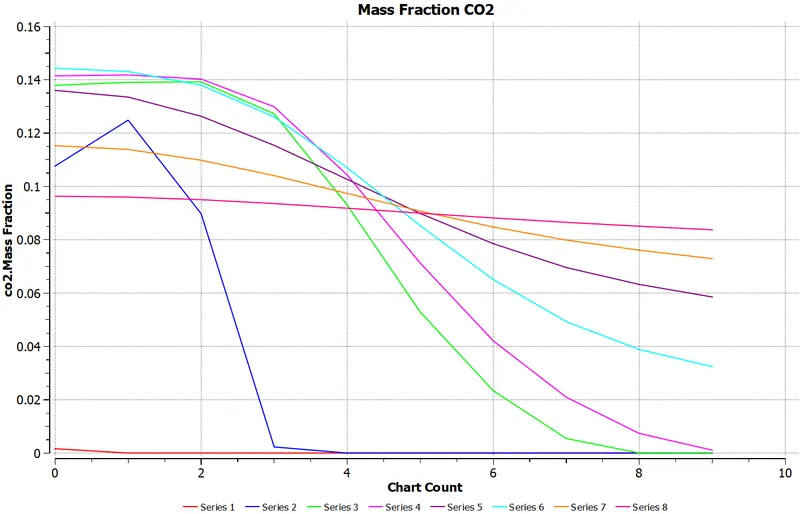
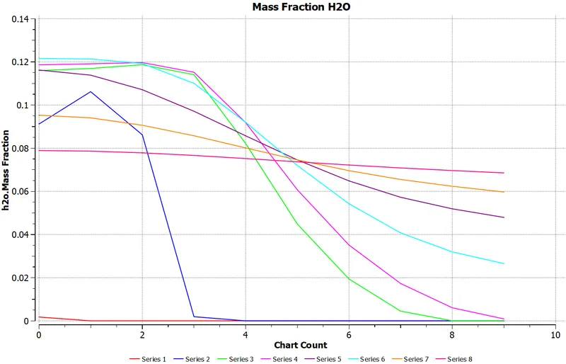
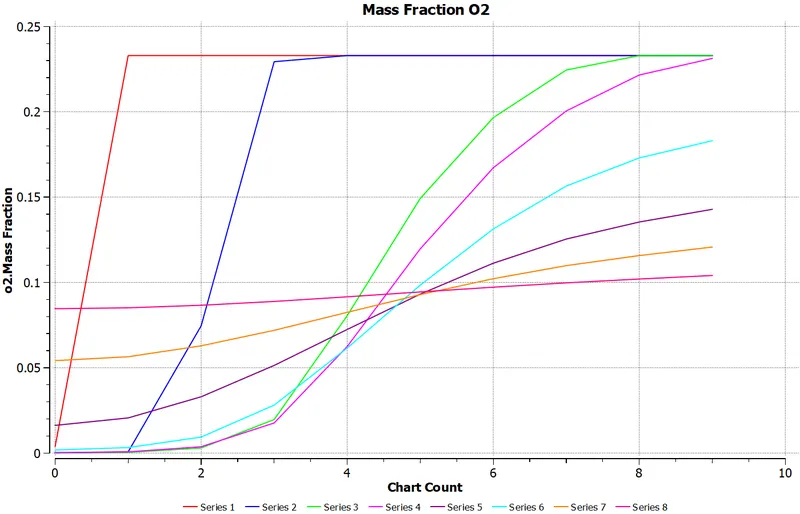
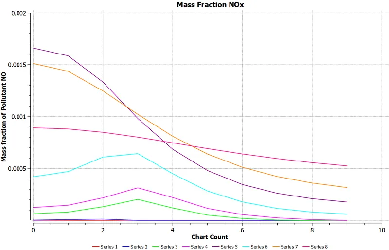
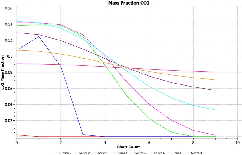
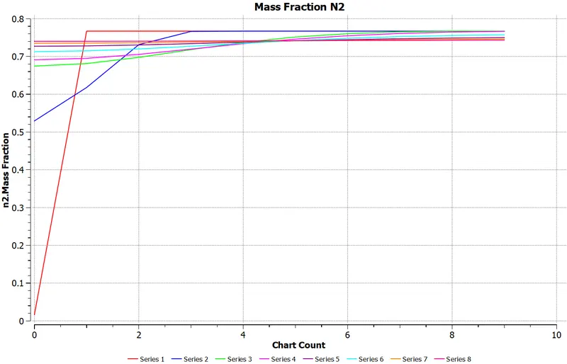
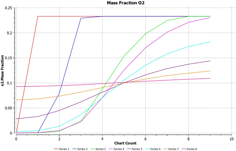
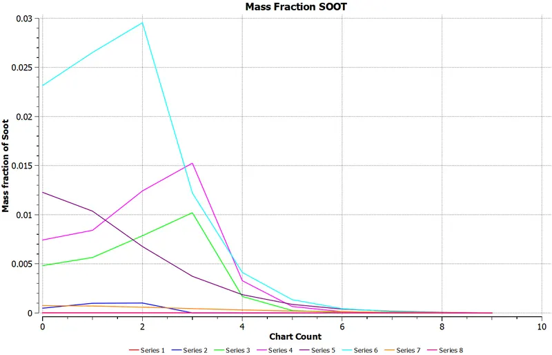
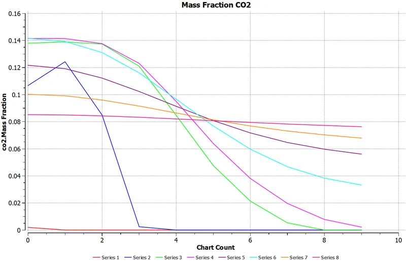
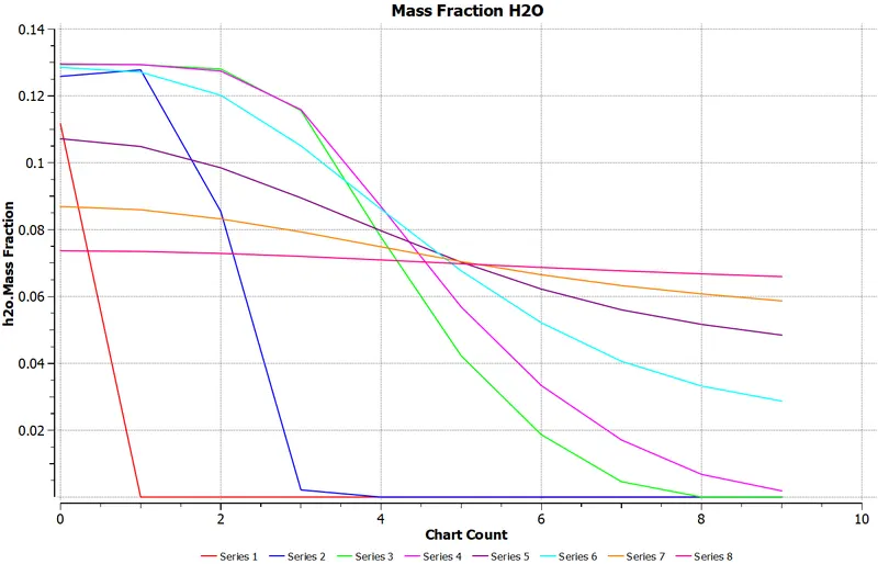
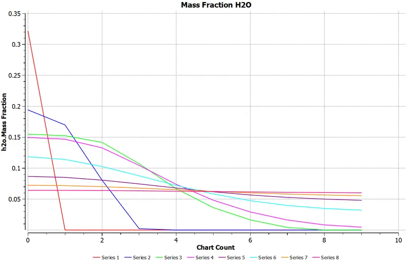
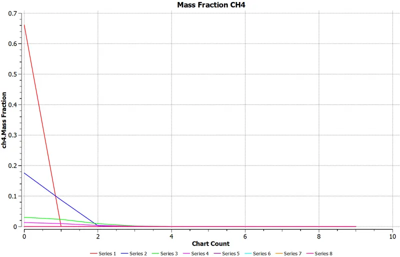
Coordinates of of Line probes
Line 1 :
Point 1---> x=0.015m y=0m z=0m
Point 2---> x=0.015m y=0.085m z=0m
Line 2 :
Point 1---> x=0.1m y=0m z=0m
Point 2---> x=0.1m y=0.085m z=0m
Line 3 :
Point 1---> x=0.25m y=0m z=0m
Point 2---> x=0.25m y=0.085m z=0m
Line 4 :
Point 1---> x=0.3m y=0m z=0m
Point 2---> x=0.3m y=0.085m z=0m
Line 5 :
Point 1---> x=0.4m y=0m z=0m
Point 2---> x=0.4m y=0.085m z=0m
Line 6 :
Point 1---> x=0.5m y=0m z=0m
Point 2---> x=0.5m y=0.085m z=0m
Line 7 :
Point 1---> x=0.6m y=0m z=0m
Point 2---> x=0.6m y=0.085m z=0m
Line 8 :
Point 1---> x=0.79m y=0m z=0m
Point 2---> x=0.79m y=0.085m z=0m
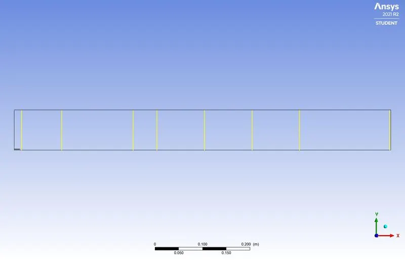
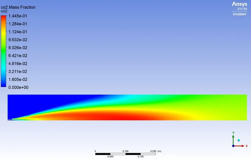
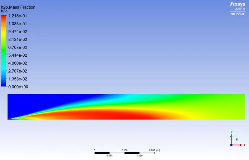
Case 1- Mole Fraction - `CH_4 =1` and `H_2O = 0`
Residual Plot
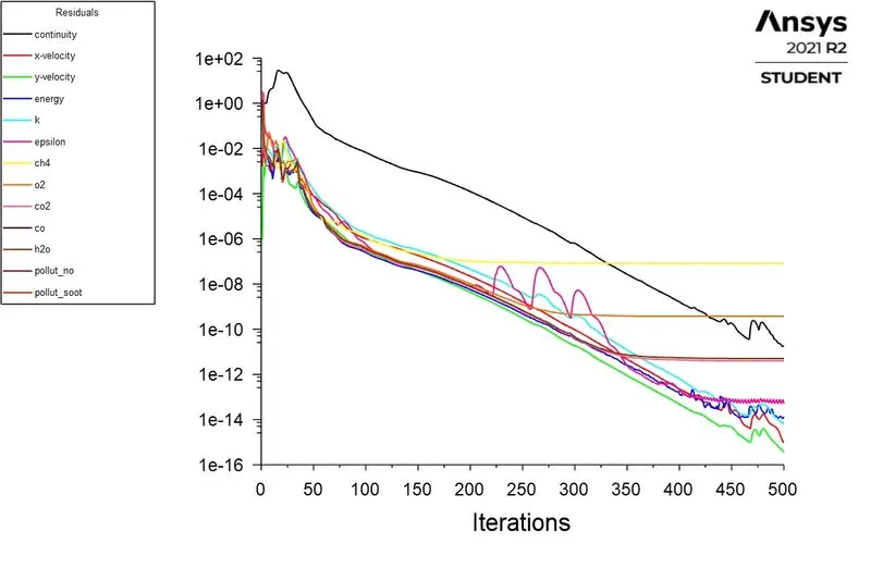
Contour and plot of `CO_2`mass fraction
Contour and plot of `H_2O` mass fraction
Contour and plot of `CH_4` mass fraction
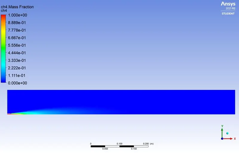
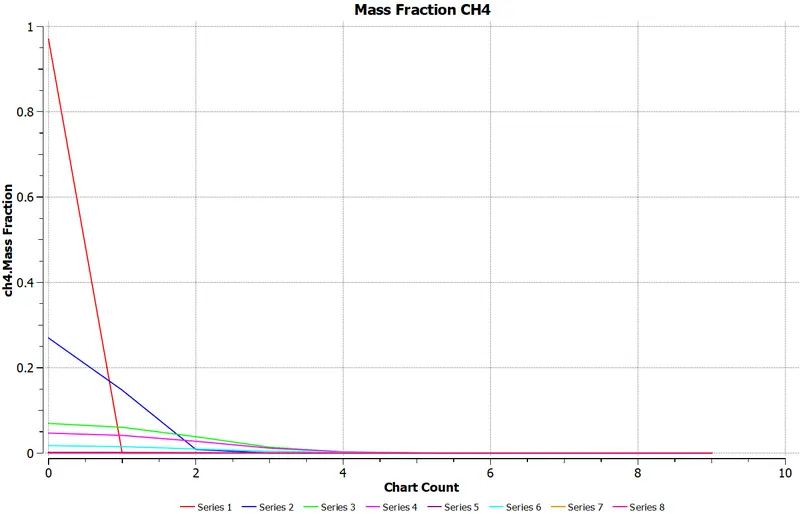
Contour and plot of `N_2` mass fraction
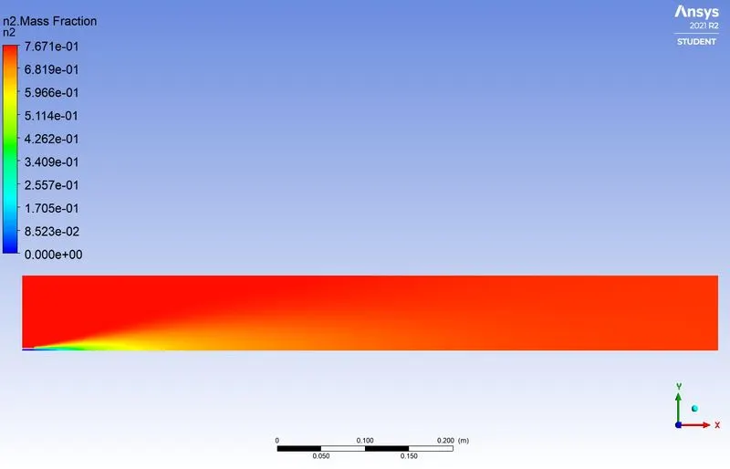
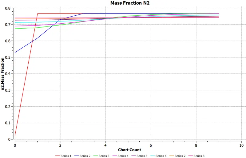
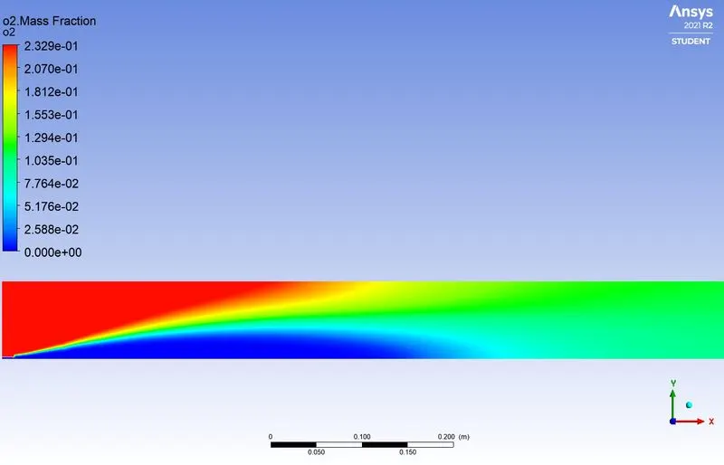
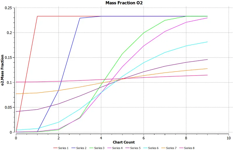
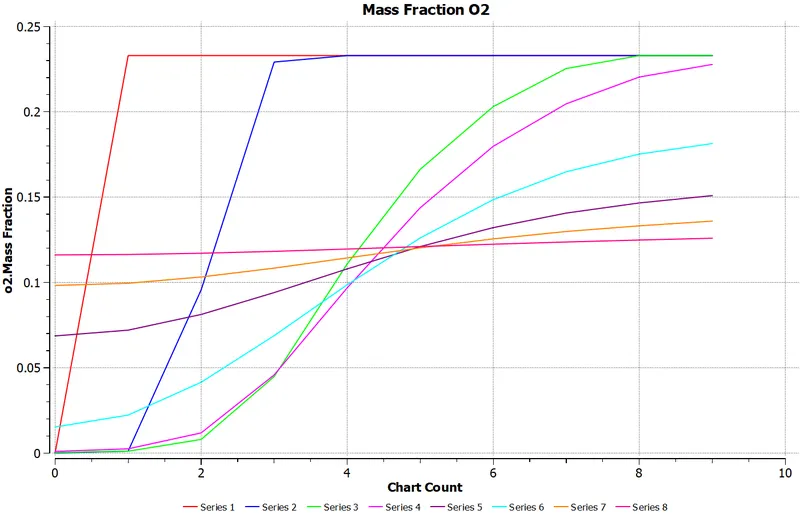
Contour and plot of `O_2` mass fraction

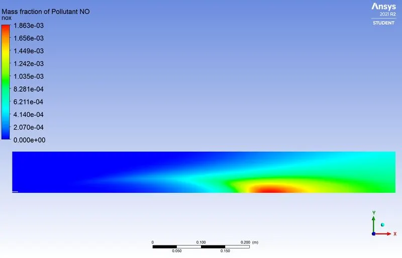
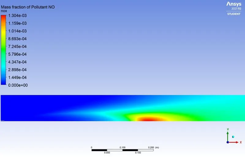
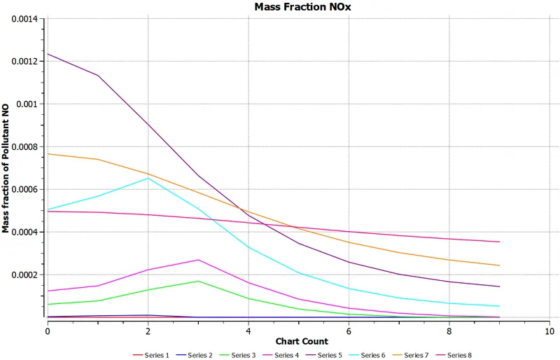
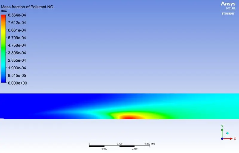
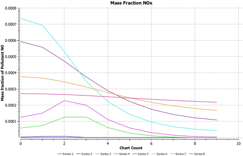
Contour and plot of `NO_X` mass fraction
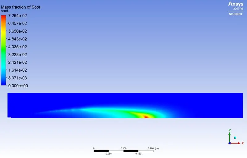
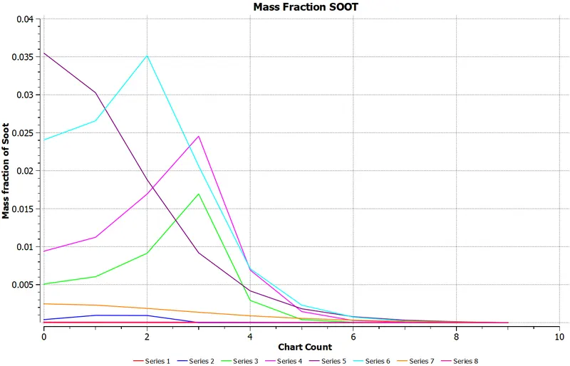
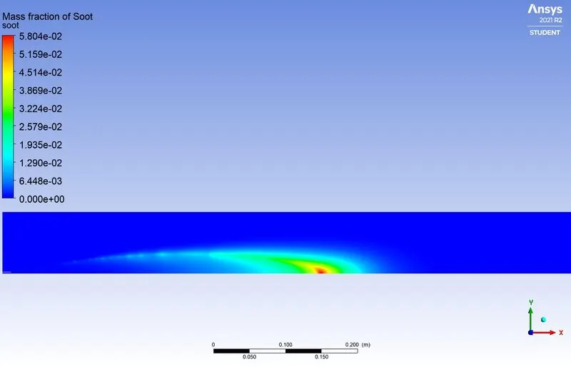
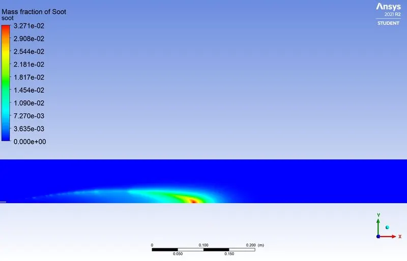
Contour and plot of SOOT mass fraction
Case 2 - Mole Fraction - `CH_4 =0.95` and `H_2O = 0.05`
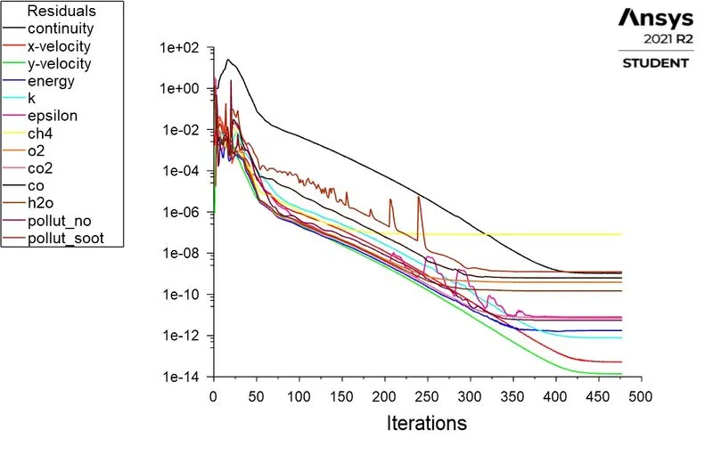
Residual Plot
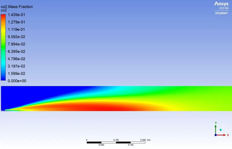
Contour and plot of `CO_2`mass fraction
Contour and plot of `H_2O` mass fraction
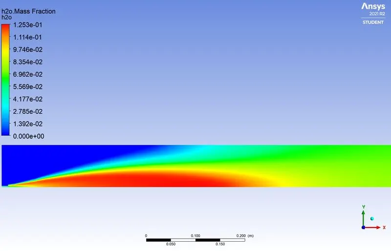
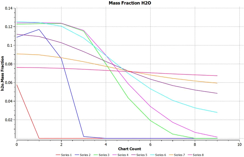
Contour and plot of `CH_4` mass fraction
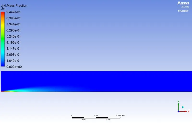
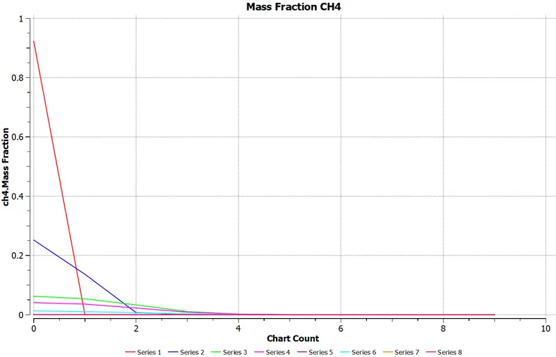
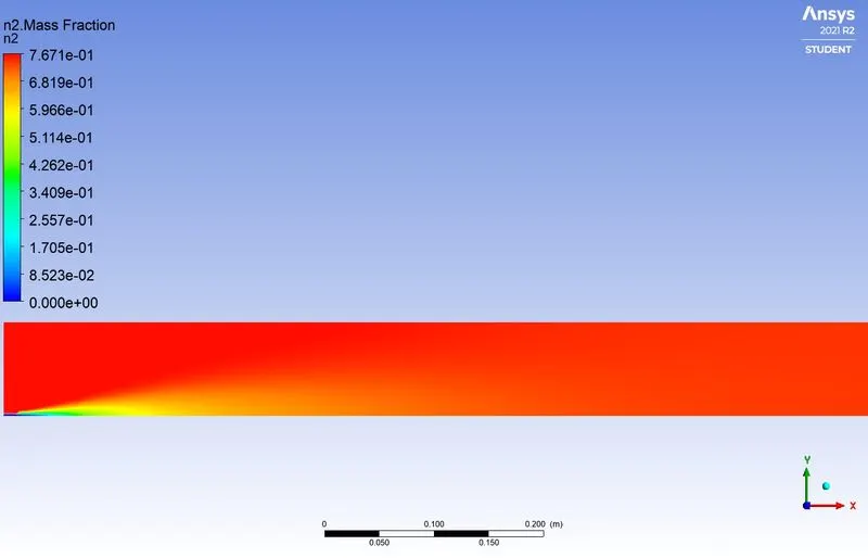
Contour and plot of `N_2` mass fraction
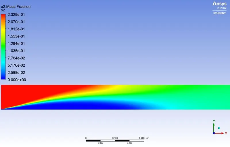
Contour and plot of `O_2` mass fraction
Contour and plot of `NO_X` mass fraction
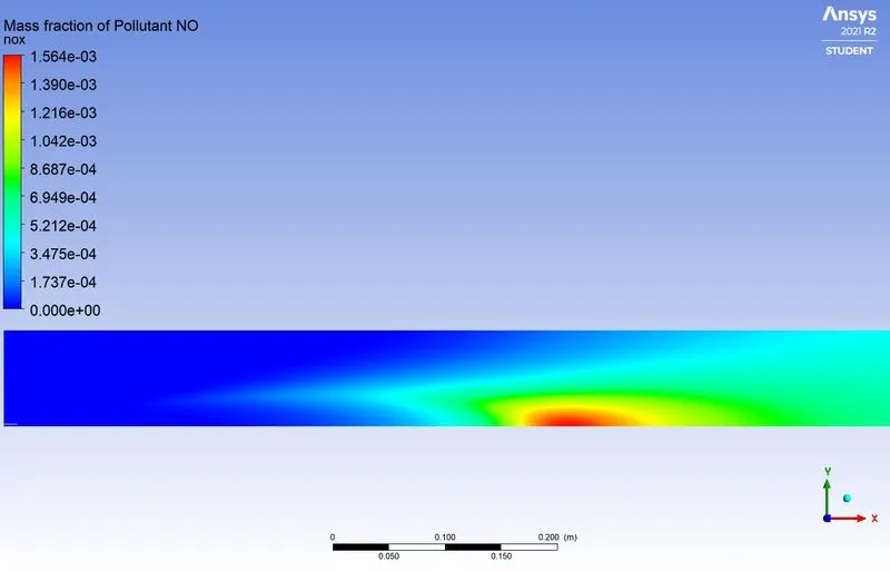
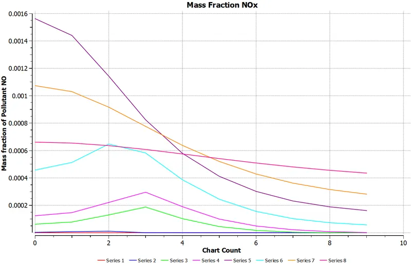
Contour and plot of SOOT mass fraction
Case 3 - Mole Fraction - `CH_4 =0.9` and `H_2O = 0.1`
Residual Plot

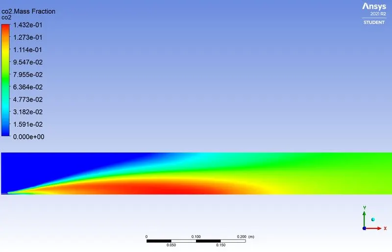
Contour and plot of `CO_2`mass fraction
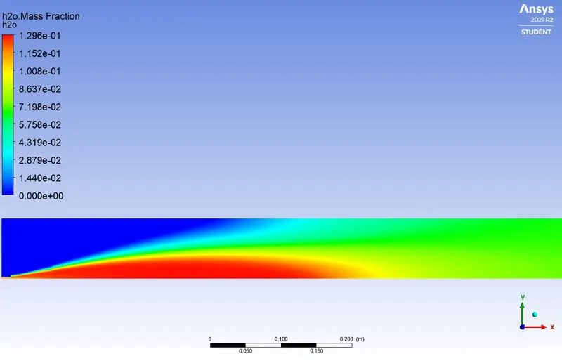
Contour and plot of `H_2O` mass fraction
Contour and plot of `CH_4` mass fraction
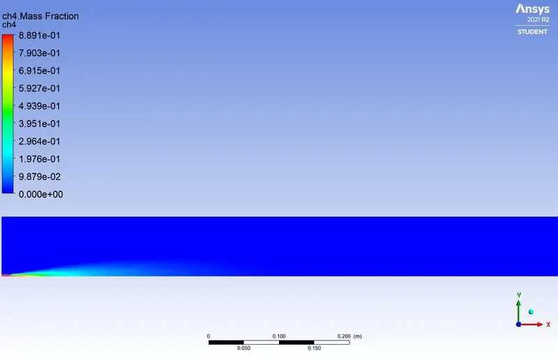
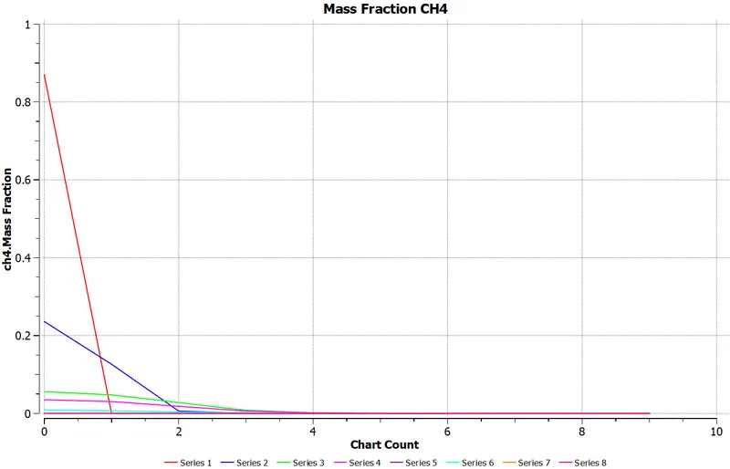
Contour and plot of `N_2` mass fraction
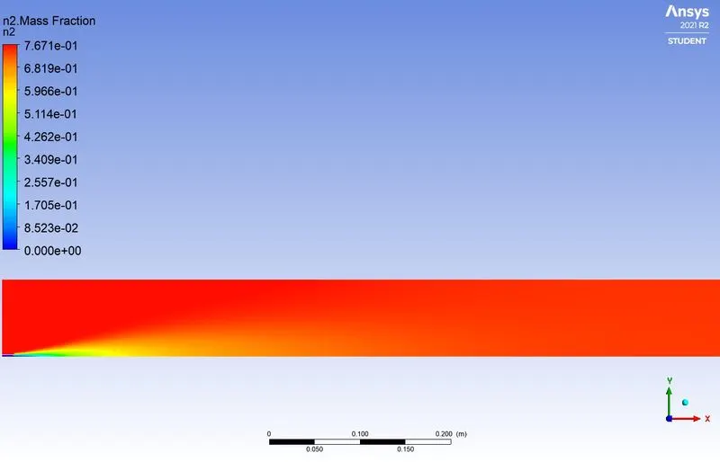
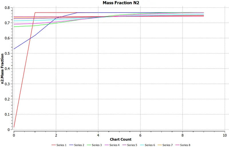
Contour and plot of `O_2` mass fraction
Contour and plot of `NO_X` mass fraction
Contour and plot of SOOT mass fraction
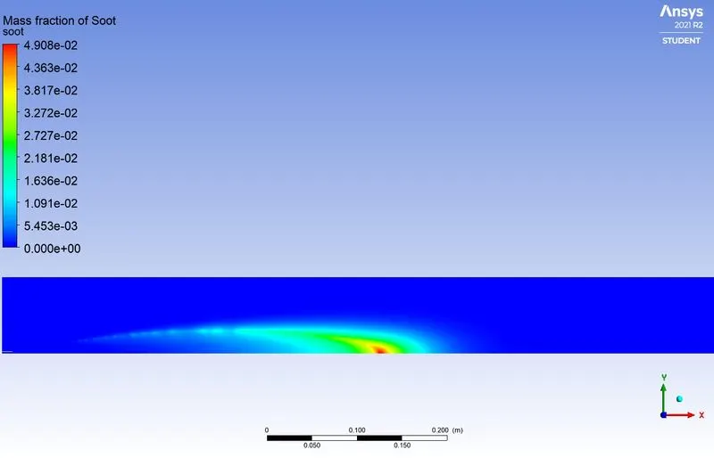
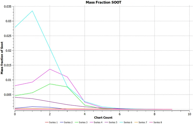
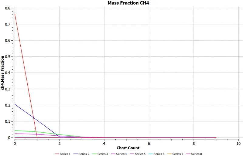
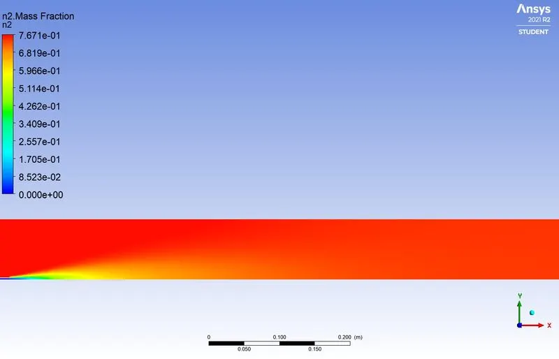
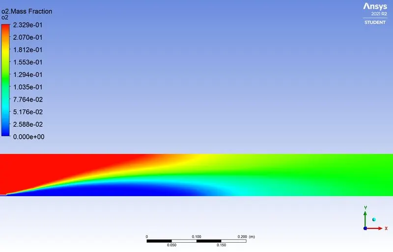
Case 4 - Mole Fraction - `CH_4 =0.8` and `H_2O = 0.2`
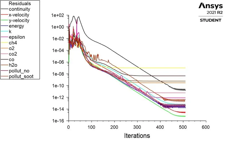
Residual Plot
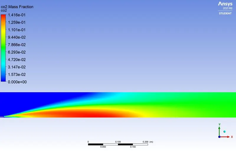
Contour and plot of `CO_2`mass fraction
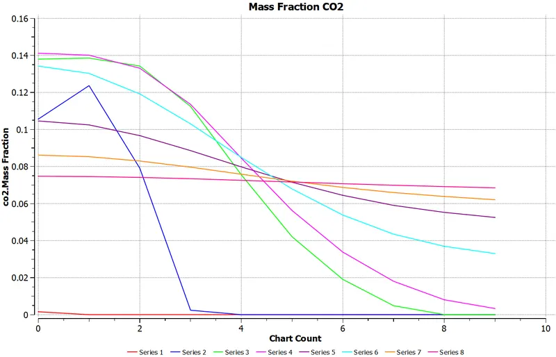
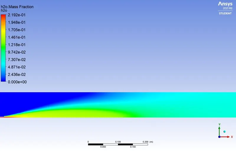
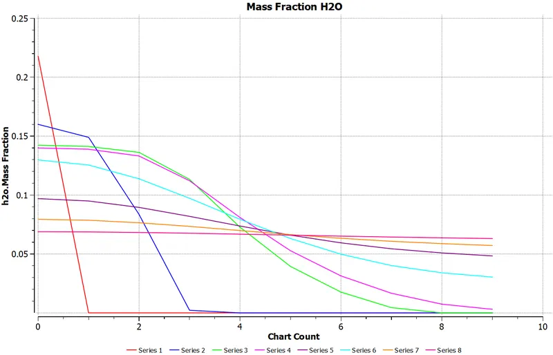
Contour and plot of `H_2O` mass fraction
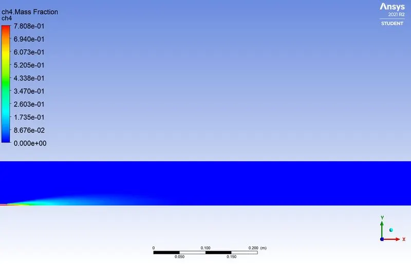
Contour and plot of `CH_4` mass fraction
Contour and plot of `N_2` mass fraction
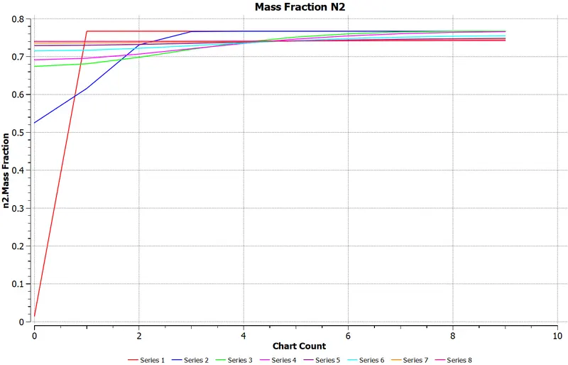
Contour and plot of `O_2` mass fraction
Contour and plot of `NO_X` mass fraction
Contour and plot of SOOT mass fraction
Case 5 - Mole Fraction - `CH_4 =0.7` and `H_2O = 0.3`
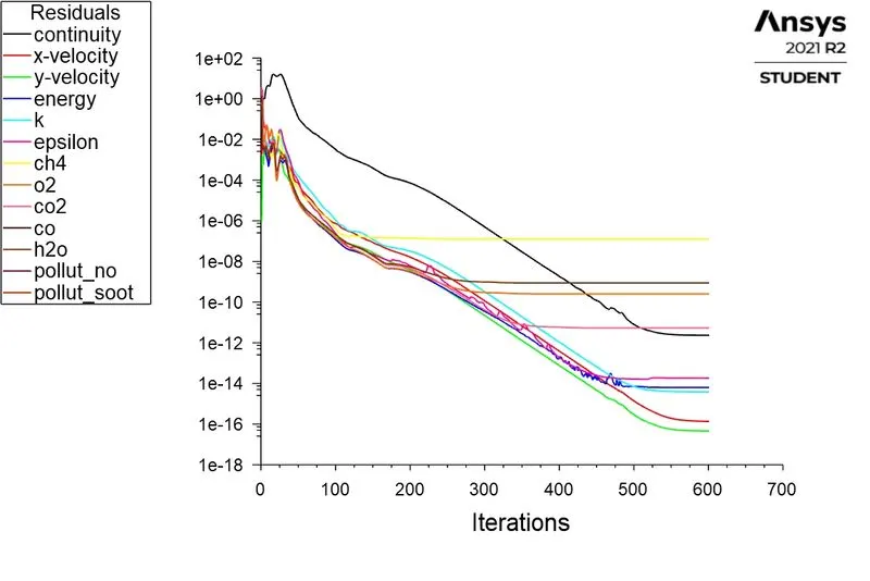
Residual Plot
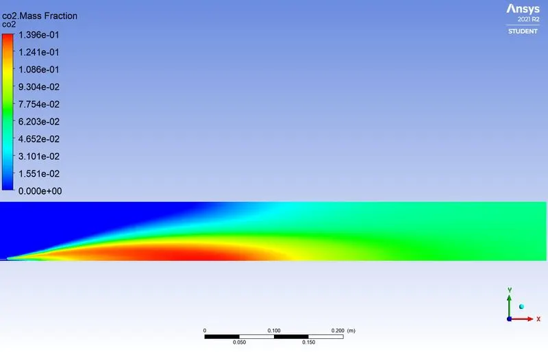
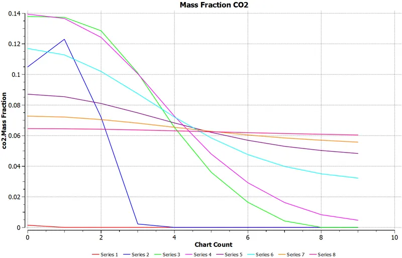
Contour and plot of `CO_2`mass fraction
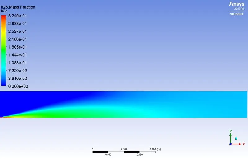
Contour and plot of `H_2O` mass fraction
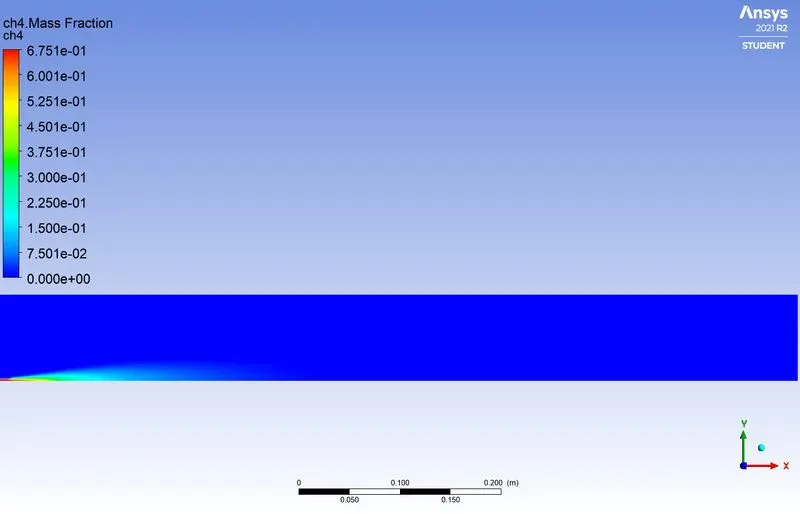
Contour and plot of `CH_4` mass fraction
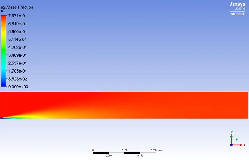
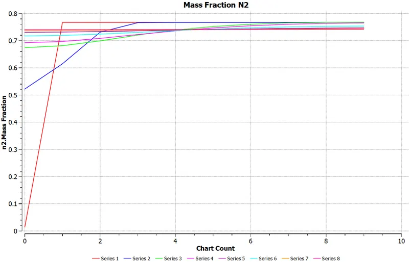
Contour and plot of `N_2` mass fraction
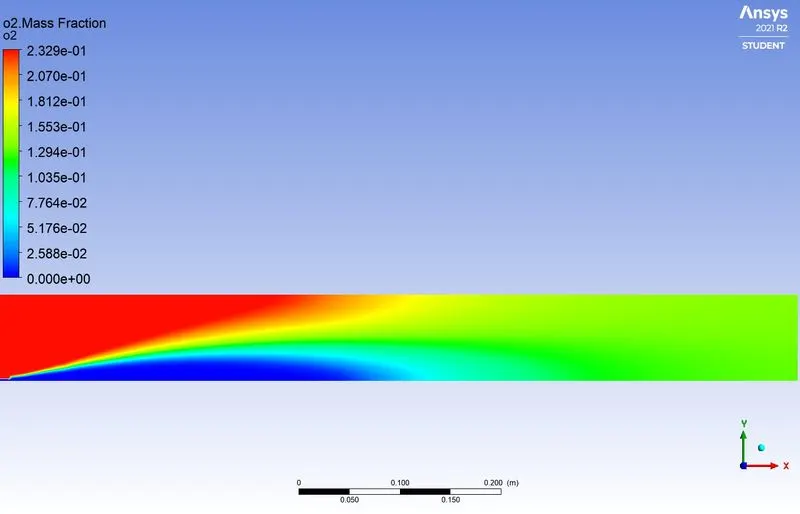
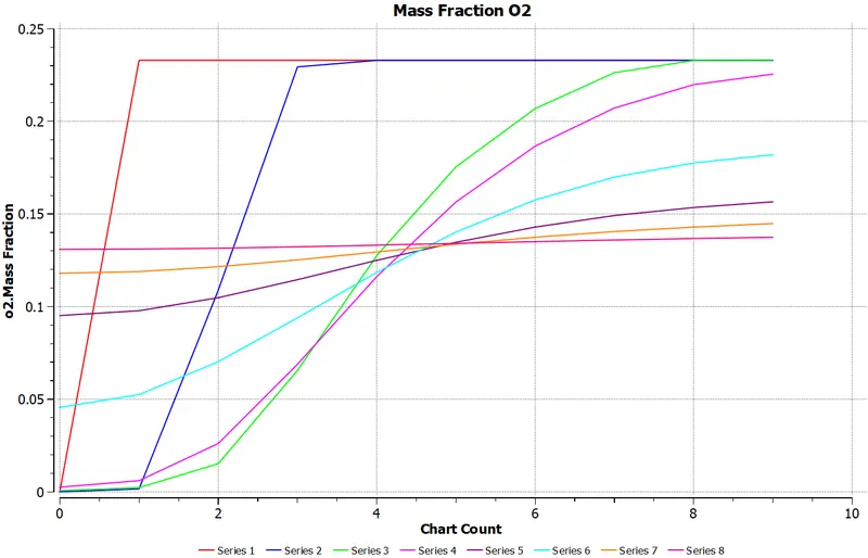
Contour and plot of `O_2` mass fraction
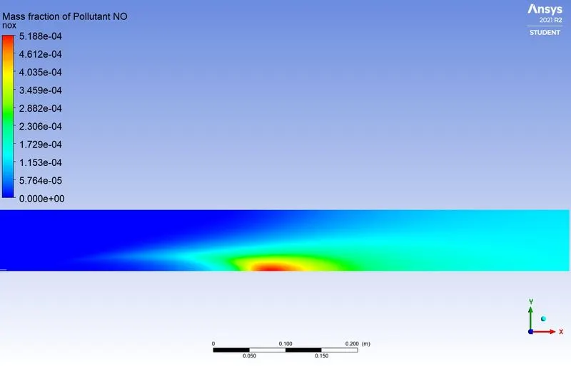
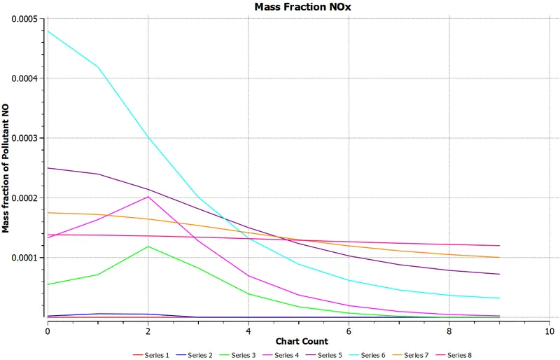
Contour and plot of `NO_X` mass fraction
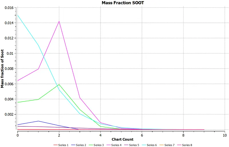
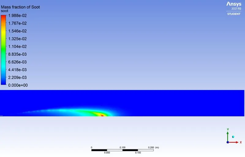
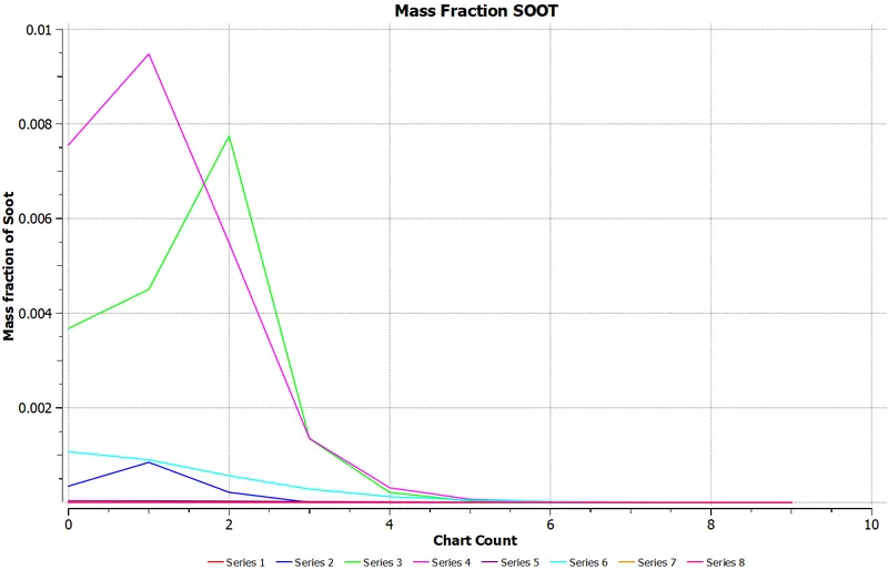
Contour and plot of SOOT mass fraction
Observation:-
|
`CH_4` |
`H_2O` |
Area weighted average mass fraction of NOx at outlet |
Area weighted average mass fraction of soot at outlet |
| 1 | 0 |
0.00064938092 |
2.3544277e-05 |
| 0.95 | 0.05 |
0.00051356117 |
7.4177037e-06 |
| 0.9 | 0.1 |
0.00040397639 |
2.756779e-06 |
| 0.8 | 0.2 |
0.00023702512 |
2.9677826e-07 |
| 0.7 | 0.3 |
0.00012658088 |
2.4098749e-08 |
Conclusion:-
- Diluting fuel with `H_2O` does indeed reduce the formation of harmful pollutants such as `NO_X` and soot at the outlet.
- The rate of reduction in the concentration of soot is greater than that of `NO_X` when diluting the fuel with water.
- Addition of water is also lead to decrease in temperature of combustor
- Fuel dilution by `H_2O` is a great way to reduce emissions. However, a trade-off must be made between the performance required and the dilution amount.
- Since soot value decreases with dilution we can say there is less wastage of fuel, i.e. complete combustion occurs.
- Eddy - dissipation model(Turbulence Chemistry Interaction) helps us to model combustion via turbulence mixing without the presence of an ignition source.
Reference:-
https://link.springer.com/article/10.1007/s00773-015-0303-8
https://cfdflowengineering.com/cfd-modeling-pollutants-nox-sox-and-soot/#Thermal_NOx