Week 4-1D Element Creation Challenge
AIM- To Mesh the component and Create 1D elements with given cross-section and DOF in Hypermesh.
Parameter -
a. Rod element:- Translational DOF should be Constrained with RBE2 link
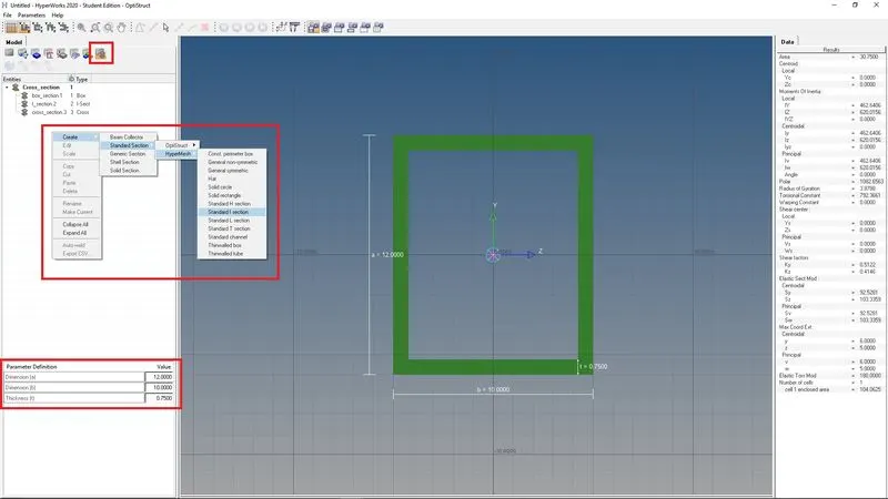
Cross-Section: BOX- Dimension a= 12 mm
dimension b=10 mm
Thickness t= 0.75 mm
b. Beam element:- All DOF should be constrained with RBE3 link
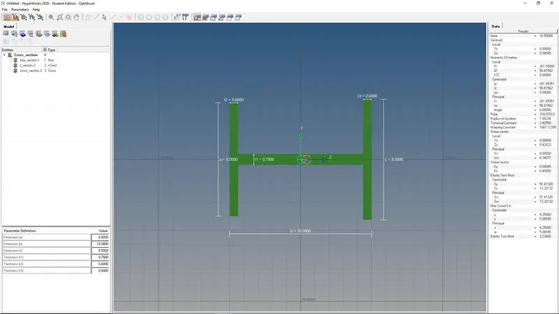
Cross-Section: I Section- Dimension a= 8 mm
Dimension b= 10 mm
Dimension c= 8.5 mm
Thickness t1= 0.75 mm
Thickness t2= .6 mm
Thickness t3= .6 mm
c. Bar element:- Constrain only x and y DOFs With RBE3 link
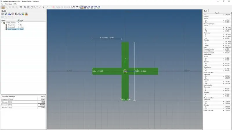
Cross-section: X section- Dimension DIM1= 5 mm
Thickness DIM2= 1.2 mm
Dimension DIM3= 10 mm
Thickness DIM4= 1.2mm
d. & e. Apply the mass of magnitude 10 with the RBE2 link
f. Join the two components with Spring elements
Procedure-
Importing and Geometry cleanup
- As the file is in IGES format, we will Import it in the Import Geometry tab.
- After Importing the model, it consists of 2 components on which we have to perform the Meshing, and 1 wireframe which is not required so we will delete that wireframe component
- Thereafter, we will check if it has a solid body, as we do not require solids for our purpose, so we will delete all the solids from the model, and we will be left with the surface only.
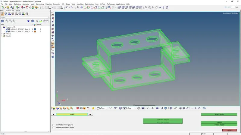
Extracting Midsurface -
- After deleting the solids, we will extract the mid surface of the model so as to perform meshing on that.
- As the model is simple in geometry we can extract the mid-surface by using the Auto mid-surface option in 1-D.
- We will extract the mid-surface only by only for both the component.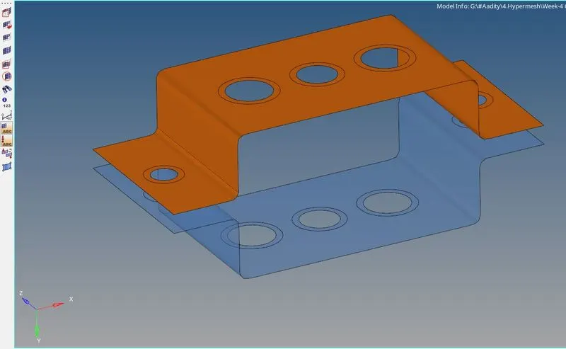
Meshing -
- After creating the Mid-surface of both the component, we need to create a washer split on the holes to perform a better meshing around it.
- Also we will toggle the unusual lines on the surface for better meshing.
- Then we will go to the Automesh tab in 2-D, provide the element size to be 5 and select the element type to be mixed.
- Then we will select the surface one by one to do mesh and hit on the mesh tab.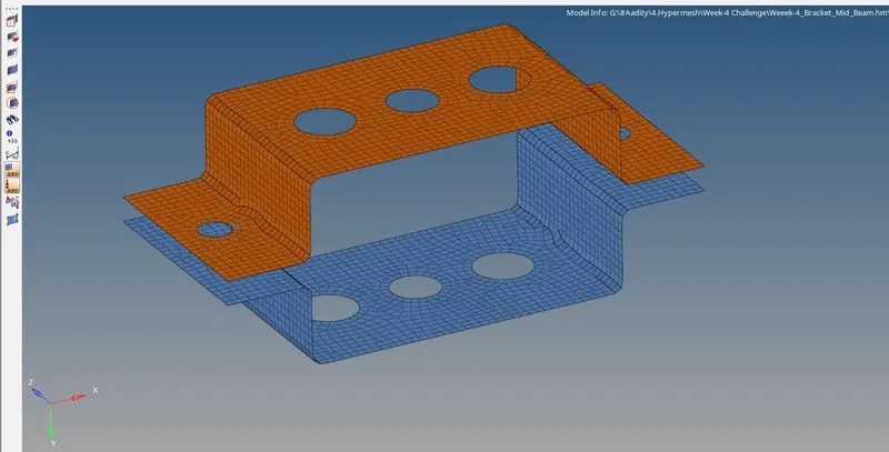
Create rigid points & 1-D element -
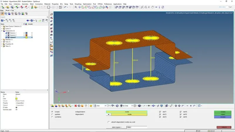
- As per the given parameter, I create RB2 & RB3 elements at the required places (a,b,c & d), and provide the DOF accordingly.
- Then I create the 1-D element rod, bar and beam at the respective node points a,b & c.
- Also apply the mass at node d and create spring between 2 brackets at desired point e.
- 
Create 1-D element in Hyperbeam -
- To create the 1D element, we need to go the Hyperbeam tab and create the required standard section in Hypermesh/Optistruct.
- And give the assigned dimension to the geometry as mentioned in the parameter.
Create Material & Property -
- We need to create the Material as Steel and assign it to the components.
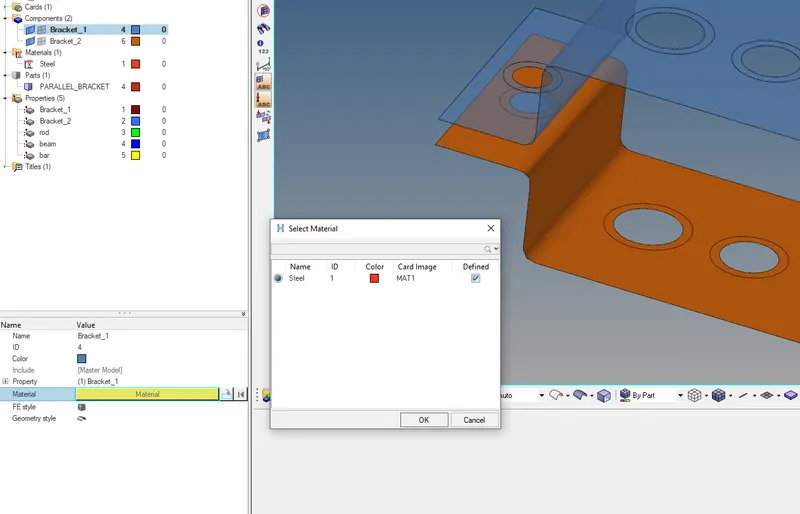
- After this, we needs to create the Property and to be assigned to the components, rod, beam bar & mass with assigning the Card ID and material.
- It should be kept in mind that the property should be assign to the appropriate required component and element only.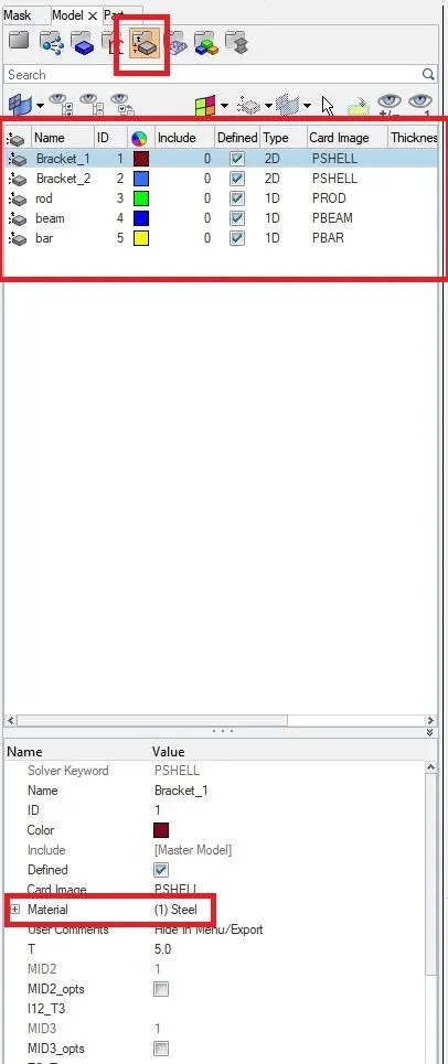
Result -
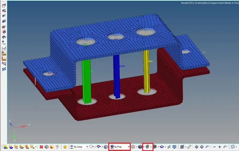
- Doing all the process, we can visualize it in 1-D detailed element representation.
- Here we can visualize all the elements and their types, also the thickness of the components.
Learning Outcome-
- Learn to extract mid-surface, meshing as per the given parameters.
- Learn how to create/assign property and material to the components.
- Learn about the RBE2 & RBE3 connections and how to create them at required places.
- Learn how to create the cross-section in the Hyperbeam workbench and assigning the dimensions as per requirement.