Week 8 - Simulating Cyclone separator with Discrete Phase Modelling
Aim:- To perform analysis on cyclone separator and calculate the separation efficiency and pressure drop.
Objective:-
- Calculate the separation efficiency and pressure drop for different cases and compare the result.
- To write a few words about any four empirical models used to calculate the cyclone separator efficiency.
- To perform an analysis by varying the particle velocity from 1 m/sec to 5 m/sec and particle diameter `5mum`
- To perform an analysis by varying the particle diameter from `1 mum` to `5mum` with inlet velocity 3m/s.
Introduction:-
Cyclone Separator-
- Cyclone separators or simply cyclones are separation devices (dry scrubbers) that use the principle of inertia to remove particulate matter from flue gases.
- Cyclone separators are one of many air pollution control devices known as pre-cleaners since they generally remove larger pieces of particulate matter.
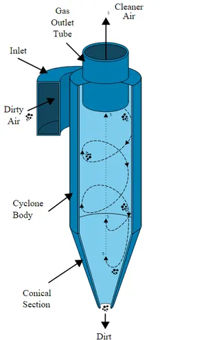
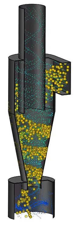
Working of Cyclone separator
- Cyclone separators work much like a centrifuge, but with a continuous feed of dirty air.
- In a cyclone separator, dirty flue gas is fed into a chamber. The inside of the chamber creates a spiral vortex, similar to a tornado. This spiral formation and the separation are shown in the above figure. The lighter components of this gas have less inertia, so it is easier for them to be influenced by the vortex and travel up it.
Contrarily, larger components of particulate matter have more inertia and are not as easily influenced by the vortex. Since these larger particles have difficulty following the high-speed spiral motion of the gas and the vortex, the particles hit the inside walls of the container and drop down into a collection hopper. - Most cyclones are built to control and remove particulate matter that is larger than 10 micrometers in diameter. However, there do exist high-efficiency cyclones that are designed to be effective on particles as small as 2.5 micrometers.
Application of Cyclone Separator
- Vacuum Cleaners
- Water Treatment
- Oil refineries
- Air Purifiers
Project - For our Project, we are going to analyze the efficiency of the Dust Collection(Vaccum Cleaners) type Cyclone Separator.
Cyclone separators are widely used as dust-collection equipment. A cyclone is essentially a settling chamber in which gravitational acceleration is replaced by centrifugal acceleration. Dust-laden air or gas enters a cylindrical or conical chamber tangentially at one or more points and leaves through a central opening. The dust particles, by virtue of their inertia, tend to move toward the outside separator wall from where they are led into a receiver. Under common operating conditions, the centrifugal separating force or acceleration may range from five times gravity in very large diameter, low-resistance cyclones to 2500 times gravity in very small, high-resistance units.
Within the range of their performance capabilities, cyclones are one of the least expensive dust-collection systems. Their major limitation is that, unless very small units are used, efficiency is low for particles smaller than five microns. Although cyclones may be used to collect particles larger than 200 microns, gravity-settling chambers or simple inertial separators are usually satisfactory and less subject to abrasion.
Procedure:-
In this project, we will analyze the result for the different particle diameter from `1 mum` to `5mum` with inlet velocity 3m/s, and different particle velocity from 1 m/sec to 5 m/sec and particle diameter `5mum
ANSYS Workbench (Fluent) is used for the solution.
Case Studies-
Case 1- Varying inlet velocity with the same particle diameter.
| Cases | Particle diameter (microns) |
Velocity |
| Case1a | 5 | 2 |
| Case 1b | 5 | 4 |
| Case 1c | 5 | 5 |
Case 2- Varying particle diameter with the same inlet velocity.
| Cases | Particle diameter (microns) |
Velocity (m/sec) |
| Case1a | 1 | 3 |
| Case 1b | 3 | 3 |
| Case 1c | 5 | 3 |
Geometry-
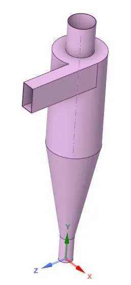
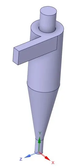
- Import the Cyclone Separator model in SpaceClaim and visualize it for cleanup.
- Fluid volume(wet volume) is then extracted from the domain, and the solid model is then suppressed for physics.
Meshing-
- Firstly we name the inlet and outlet by selecting the face'
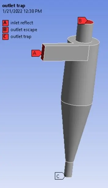
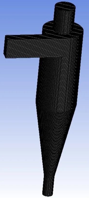
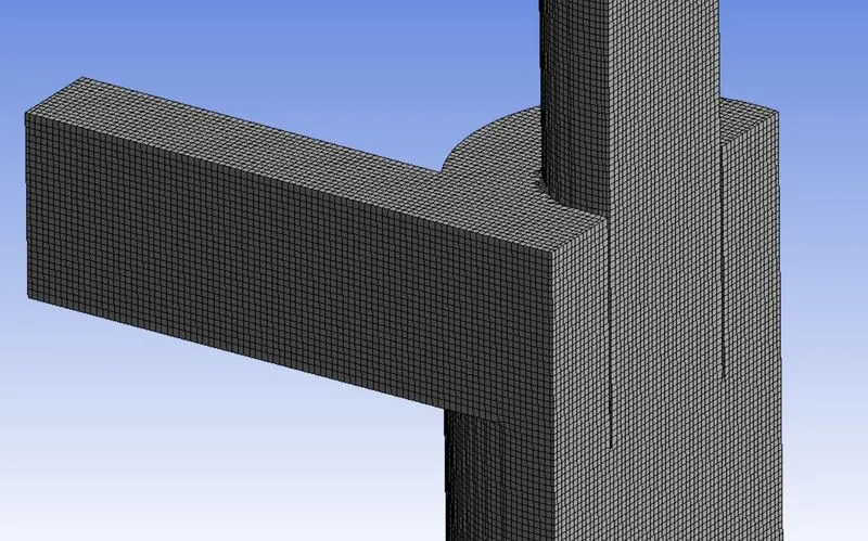
- Body fitted cartesian Meshing is done with an element size of 3.5 mm.
- The cartesian mesh is deployed because it produces smooth and consistent mesh elements which are best suited to capture the flow path of a particle.
- Cell count - 473504
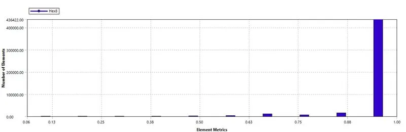
Mesh Quality
Setup-
|
Solver Type |
Pressure-Based |
|
Velocity Formulation |
Absolute |
|
Time |
Steady |
|
Gravity |
negative y-direction (9.81 m/s) |
|
Viscous Model |
K-epsilon > RNG > Swirl Dominated Flow |
|
Material |
Fluid type- Air |
|
Model |
Discrete Phase Model |
|
Boundary Condition |
Inlet - Velocity inlet Outlet 1- Pressure outlet (Gauge pressure = 0 Pa) Outlet 2- Pressure outlet (Gauge pressure = 0 Pa) Walls - Stationary wall with no-slip condition |
|
Solution Method |
pressure-velocity coupling- SIMPLE |
|
Initialization |
Standard Initialization |
Discrete Phase Model
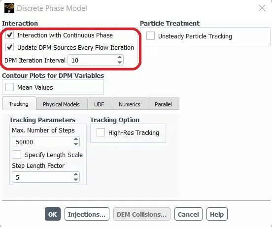
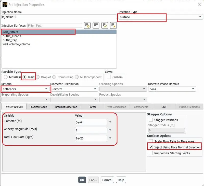
Inlet:
Type - Velocity inlet = "Respective velocity as per each case set-up (m/s)"
DPM - Reflect (Here particle rebounds off the boundary with change in momentum. However, the coefficient of restitution in the normal and tangential direction is by default set to one. Due to this in case the particle rebounds to the inlet boundary there is no change in momentum after reflection)
Top outlet
Type - Pressure outlet = 0 gauge pressure (i.e. atmospheric pressure)
DPM - Escape (The particle is allowed to leave the outlet boundary with discontinuation of the trajectory calculations and particle fate is reported as "Escape")
Bottom outlet
Type - Pressure outlet = 0 gauge pressure (i.e. atmospheric pressure)
DPM - Trap (The particle gets caught at the boundary face with the termination of the trajectory calculations and particle fate is reported as "Trapped")
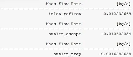
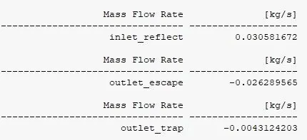
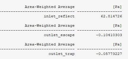
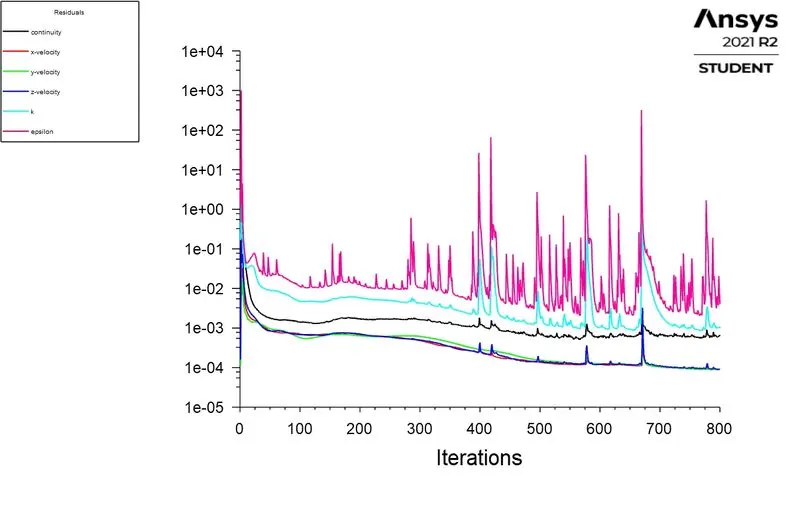
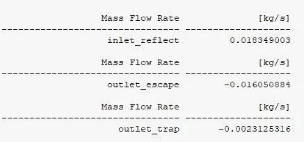
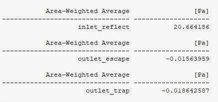
Solution Reports- Flux report for Mass Flow Rate at the outlet is created and the pressure report at inlet and outlet is computed.
Post Processing-
CASE 1a - Particle velocity from 2 m/sec and particle diameter `5mum`.
DPM Report

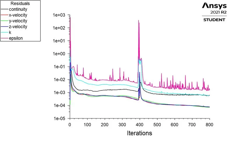
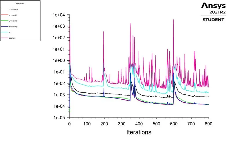
Residuals
Mass Flow Rate Report
Area Average Pressure Report
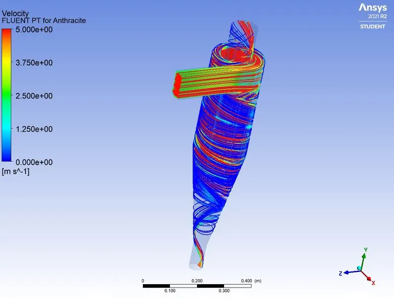
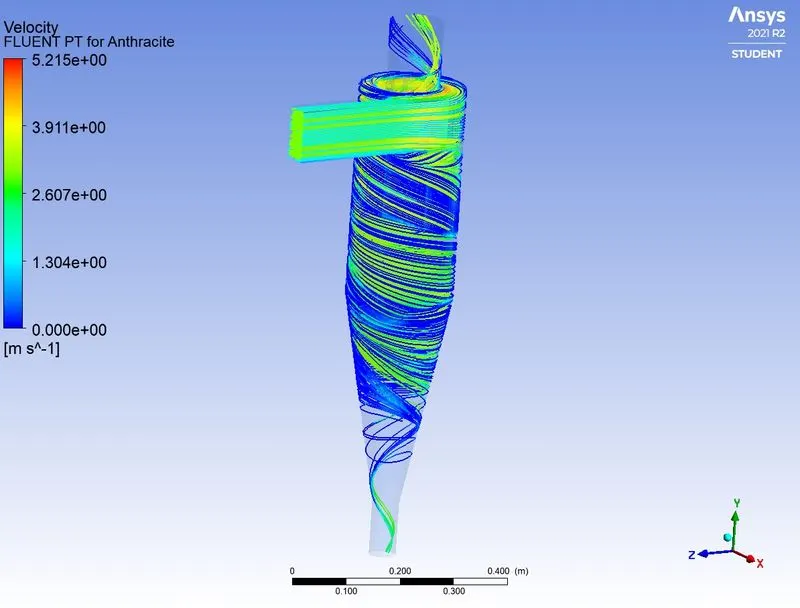
Velocity Contour
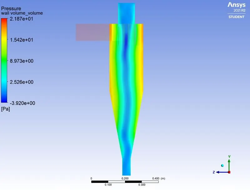
Pressure Contour plane
Animation Particle Residence Time
CASE 1b - Particle velocity from 4 m/sec and particle diameter `5mum`.
DPM Report

Residuals
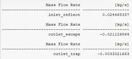
Mass Flow Rate Report
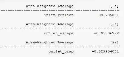
Area Average Pressure Report
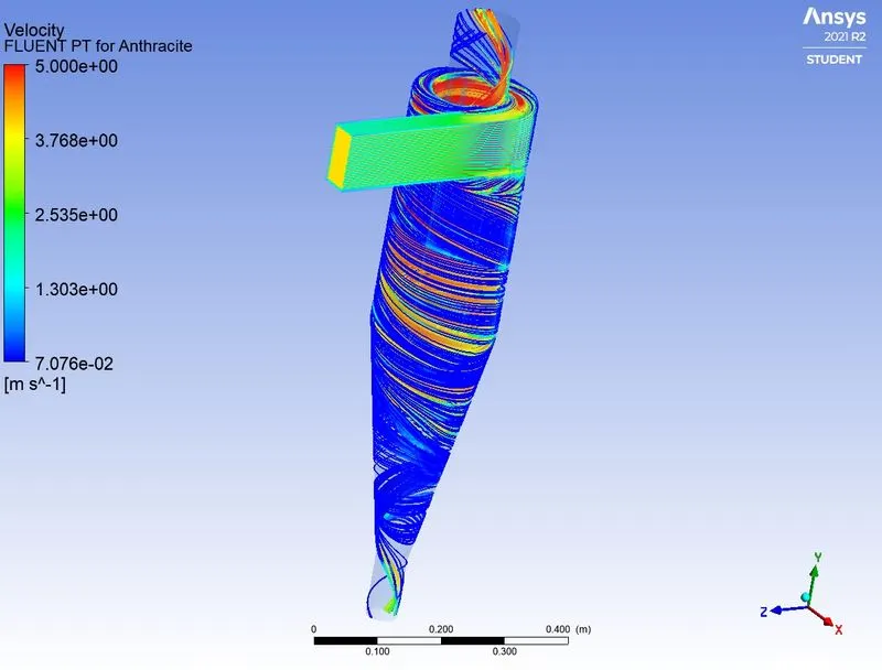
Velocity Contour
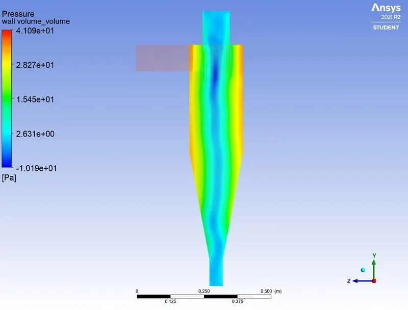
Pressure Contour plane
Animation Particle Residence Time
CASE 1c - Particle velocity from 5 m/sec and particle diameter `5mum`.
DPM Report

Residuals
Mass Flow Rate Report
Area Average Pressure Report
Velocity Contour
Pressure Contour plane
Animation Particle Residence Time
Observation table - This case is intended to study the effect of fluid inlet velocity on the separation efficiency with the same diameter-sized particles.
| Cases | Particle Diameter (microns) | Particle Velocity (m/s) | Particles Tracked | Particles Escaped | Particles Trapped | Incomplete Particles |
Efficiency |
Pressure drop(Pa) |
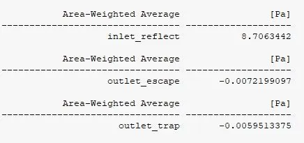
| Case 1a | 5 | 2 | 392 | 82 | 46 | 264 | 11.73 % | 8.7063 |
| Case 1b | 5 | 4 | 392 | 62 | 287 | 43 | 73.21 % | 38.7858 |
| Case 1c | 5 | 5 | 392 | 60 | 331 | 1 | 84.44 % | 62.8147 |
The Separation Efficiency can be calculated by
`eta_i =`Trapped Particle / Total number of particle
Note: The efficiency is calculated by neglecting the number of incomplete particles
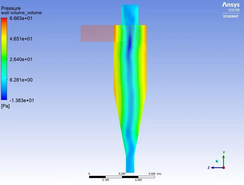
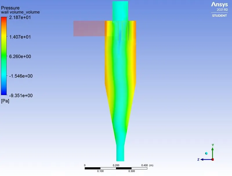
- In the above table, it is shown that the fluid inlet velocity has a direct impact on the pressure drop. The more the fluid inlet velocity the more will be the pressure drop.
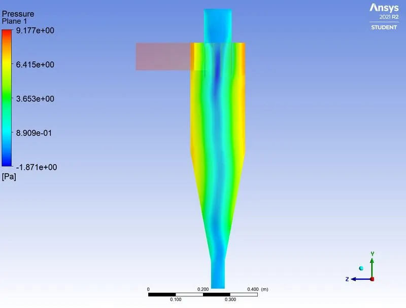
- In the case of lesser velocity, it results in lesser pressure drop but significantly affects the separation efficiency. It is due to the fact that lesser pressure drop contributes to less acceleration of the particles to the outflow. The inertial influence on the particles will significantly reduce due to less acceleration.
- Due to increasing in acceleration the velocity increases and subsequently also the mass. And increased mass improvize inertial forces. Because of this, particles tend to swirl upwards in the upper midsection of the separator due to less inertia and force balance due to gravity.
- The balanced force distribution leads to the rotation of the particles at a certain height and hinders the particle escape/trap.
- Accordingly, the particles are more likely to escape from the top outlet due to a comparatively larger outlet cross-section and high-pressure drop at the top outlet region. These particles also do not much interact with the separator walls and swirl in the center of the walls (around the axis at a lesser radial distance).
- Conversely, in cases with higher velocity, the resulted pressure drop is much higher. Due to this, the particles possess higher acceleration to the outflow and enhance the inertial effects. The particles with higher velocity and acceleration (in terms of increased mass) increase the significance of centrifugal force.
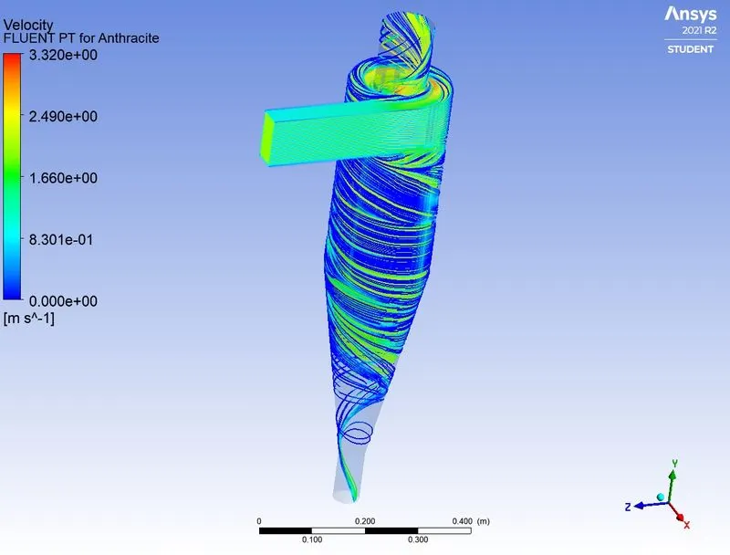
- These particles will swirl with higher tangential velocity components and will interact with the separator walls. The particle residence time is also very less as compared to the case with lesser velocity. Due to increased inertial effects, the particles rush to the bottom outlet under the influence of gravity. This causes more particles to get trapped at the bottom and very less particles escape, which certainly increases the separation efficiency.
CASE 2a - Particle velocity from 3 m/sec and particle diameter `1mum`.
DPM Report

Residuals
Mass Flow Rate Report
Area Average Pressure Report
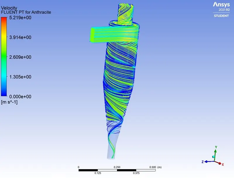
Velocity Contour
Pressure Contour plane
Animation Particle Residence Time
CASE 2b - Particle velocity from 3 m/sec and particle diameter `3mum`.
DPM Report

Residuals
Mass Flow Rate Report
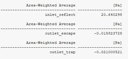
Area Average Pressure Report
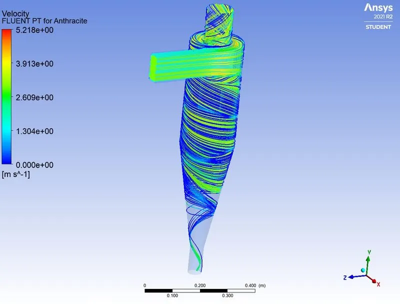
Velocity Contour
Pressure Contour plane
Animation Particle Residence Time
CASE 2c - Particle velocity from 3 m/sec and particle diameter `5mum`.
DPM Report

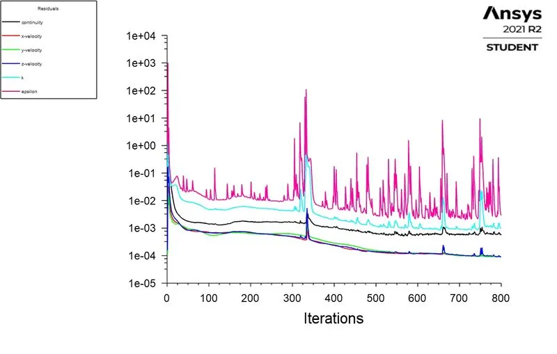
Residuals
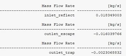
Mass Flow Rate Report
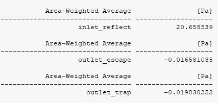
Area Average Pressure Report
Velocity Contour
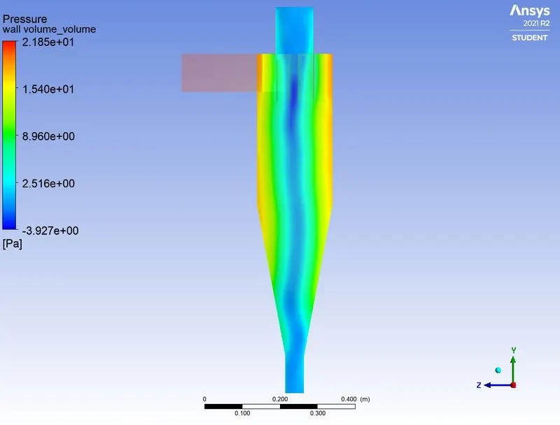
Pressure Contour plane
Animation Particle Residence Time
Observation Table - This case study is made to analyze the effect of particle diameter on the separation efficiency with the same velocity.
| Cases | Particle Diameter (microns) | Particle Velocity (m/s) | Particles Tracked | Particles Escaped | Particles Trapped | Incomplete Particles |
Efficiency |
Pressure drop(Pa) |
| Case 1a | 1 | 3 | 392 | 185 | 40 | 167 | 10.20 % | 20.6641 |
| Case 1b | 3 | 3 | 392 | 128 | 55 | 209 | 14.03 % | 20.6403 |
| Case 1c | 5 | 3 | 392 | 64 | 63 | 265 | 16.07 % | 20.6585 |
The Separation Efficiency can be calculated by
`eta_i =`Trapped Particle / Total number of particle
Note: The efficiency is calculated by neglecting the number of incomplete particles
- From the table, it is shown that the smaller particles have less density as compared to the larger ones and are less inertially influenced.
- Smaller particles do not much interact with the separator walls due to lesser density, they tend to swirl with flue gases at the maximum axial velocity region (generally at zero radius or at the vertical midsection of the separator).
- The particle residence time of the smaller diameter-sized particles is comparatively less. These particles have less centrifugal effects than gas drag force. Because of this, they tend to escape with flue gases and do not get much influenced by the cyclonic effect.
- Whereas large-sized particles possess comparatively higher inertia due to more density.
- The larger particles swirl and interact with separator walls as they are much dominated by the tangential velocity component/centrifugal effects. Due to this the particles slowly move down along the separator walls with a certain descending angle.
- Due to higher centrifugal influence, they do not spin in the midsection of the separator.
- However, these particles spend a pretty much amount of time in the region of the cyclone as compared to the smaller particles.
- As a function of time, the larger particles lose momentum and inertial energy and fall off to the bottom (where they are trapped) under the gravitational influence.
- The separation efficiency tends to increase with the larger particles as compared to smaller ones.
- These smaller diameter-sized particles tend to escape with the gas flow and almost 1/3rd of these are collected at the bottom.
- In contrast to it, larger particles show good trapping separation efficiency as they separate easily from the mixed flow under cyclonic conditions. Accordingly resulted in pressure drop is similar for all cases as this study evaluates the case on varying particle size with the same inlet velocity.
Various models based on certain assumptions and concerned flow physics are discussed.
Iozia and Leith model -
- This model is based on force balance.
- The model assumes that a particle carried by a vortex endures the influence of two forces, centrifugal force, and flow resistance.
- The collection efficiency (`eta_i`) of particle diameter`d_pi` can be calculated from,
`eta _i = 1/(1+(d_(pc)/(d_(pi)))^beta)`
Li and Wang model -
- This model includes particle bounce or re-entrainment and turbulent diffusion at the cyclone wall.
- A two-dimensional analytical expression of particle distribution on the cyclone is obtained.
- The resultant expression of the collection efficiency for a particle of any size is given as
`eta_i=1−exp{− lamda theta_1}`
Koch and Licht model - This model recognized the inherently turbulent nature of the cyclones and the distribution of gas residence times within the cyclone.
The model described particle motion in the entry and collection regions with the following assumptions,
- The tangential velocity of a particle is equal to the tangential velocity of the gas flow, i.e. there is no slip in the tangential direction between the particle and the gas.
- The tangential velocity is related to the radius of the cyclone by μRn=const.
- A force balance and an equation on the particles collection yields the grade efficiency ηiηi,
`eta_i = 1−exp{−2 [(GT_iQ)/D^3 (n+1)]^(0.5/(n+1))}`
Lapple model -
- Lapple model was developed based on force balance without considering the flow resistance.
- Lapple assumed that a particle entering the cyclone is evenly distributed across the inlet opening.
- The particle that travels from the inlet half-width to the wall in the cyclone is collected with 50% efficiency.
- The efficiency of collection of any size iof particle is given by,
`eta _i = 1/(1+(d_(pc)/(d_pi))^2`
Conclusion:-
- For simulating the case of a cyclone separator, the Euler-Lagrangian model has been used with the K-epsilon (RNG) turbulence model.
- The separation efficiency and pressure drop have been calculated for varying particle diameter and for varying inlet velocity.
- The obtained results are promising and are able to imitate appropriate physics. The following conclusions can be drawn from the present study:
Case study 1- Varying particle diameter with the same inlet velocity.
- The smaller particles tend to escape due to less density and inertia which results in lower separation efficiency. In contrast to it, larger particles possess higher density and inertial effects due to which they get collected to the bottom under the gravitational influence.
- The particle residence time is more in the case of larger particles.
- The pressure drop is almost the same for all the cases.
Case study 2- Varying inlet velocity with the same particle diameter
- The particles with lesser velocity escape or get stuck in the re-circulation region due to less pressure difference leading to less separation efficiency. However, the particles with high velocity are accelerated to the outlet due to the high-pressure difference and get trapped at the bottom. This certainly increases the separation efficiency for the particles with high velocity.
- The particle residence time is more in the case of particles with lesser velocity.
- Pressure drop increases with an increase in gas inlet velocity. It increases the separation efficiency of the cyclone separator. However, too much pressure drop increases the operating costs and conditions of the cyclone separator.
References:-
https://energyeducation.ca/encyclopedia/Cyclone_separator
https://www.sciencedirect.com/topics/engineering/cyclone-separator